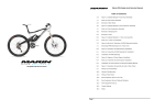
1
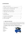
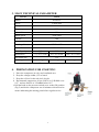
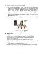
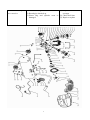
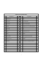
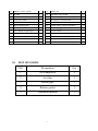
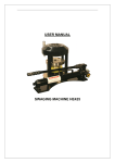
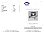
Warrior AIR COMPRESSOR
OPERATION MAMUAL
AC50VLF
BEFORE OPERATION BE FAMILIAR
WITH THE OPERATION MANUAL FIRST
CONTENTS
1 BRIEF DESCRIPTION……………………………………2
2 GENERAL VIEW AND MAIN COMPONENTS …………2
3 MAIN TECHNICAL PARAMETERS
…………………2
4 PREPARATION FOR STARTING ………………………3
5 OPERATION AND ADJUSTMENT ……………………3
6 CAUTIONS ………………………………………………4
7 MAINTENANCE…………………………………………4
8 TROUBLES AND REMEDIES …………………………5
9 PARTS ILLUSTRATION…………………………………6
10 LIST OF GOODS………………………………………8
1. BRIEF DESCRIPTION
This air compressor is of novel design and excellent workmanship, having the advantages of
compact construction, fine appearance, light weight, easy operation, high safety and low
noise; it can be widely used in machinery including chemical industry, spray, automatic
control & DIY system and other fields where compressed air is required.
2. GENERAL VIEW AND MAIN COMPONENTS (Fig.l)
(1) Fan cover
(2) Muffler
(3) Front shroud
(4) Switch assembly
(5) Tank
(6) Rubber mat
(7) Pump head
(8) Wheel
Fig.1
1
3. MAIN THCHNICAL PARAMETER
ITEM
DATA
Model
AC50VLF
Power
2.2Kw/3HP
FL
230V
FL-50L
50Hz
Voltage
Frequency
Motor Poles
2P
Rated Speed
2850 r/min
Current
Theoretic
10A
14.6CFM
Discharge
Discharge
Discharge
Discharge Pressure
Pressure
115PSI/0.8MPa
Discharge
Restart Pressure
80 PSI/0.55MPa
Delivery
Tank
Capacity
(at 115PSI/0.8MPa)
Dimensions
Air Outlet Size
Net Weight
50L
25L
77×38×75cm
30L
62x36x64cm
50L
65x36x64cm
43.2kg
77X33X73cm
28kg
30kg
38kg
80L
100L
92×38×83cm
109×43×83cm
1/4”
53kg
57kg
4. PREPAPATION FOR STARTING
1.
2.
3.
4.
Place the compressor in a dry and ventilated area.
Keep the voltage within±5% of rated.
Keep the oil level in the red circle leveler.
Recommend compressor oil use SAE30 or L-DAB68 over
10℃ and use SAE10 or L-DAB46 below 10℃.
5. Pull the knob on the pressure switch cover to the ON position
(Fig.2) and let the compressor run 10 minutes with no load to
ensure lubricating the moving parts before regular service.
Fig.2
2
5. OPERATION AND ADJUSTMENT
1)The compressor is controlled by pressure switch when operational. It will stop
automatically as pressure increases to maximum and will restart automatically when
pressure decreases to minimum. The rated pressure has been factory set and MUST
never be altered. As soon as the motor switched off the compressed or the
compressor is being stored the air in the discharge pipe should be released. This is
the necessary condition for restart or the motor could be damaged.
2)The output pressure of compressed air can be adjusted by regulating valve. Pull up
the knob of regulation valve and turn it clockwise to increase or counterclockwise to
decrease the pressure (Fig.3).
3)To stop the compressor when operating press the pressure knob switch to the OFF
position.
6. CAUTIONS
Fig.3
(1)
(2)
(3)
(4)
(5)
(6)
Before operation or starting of compressor put in oil plug and air filter.
Never unscrew any connecting part when the tank is in pressure condition.
Never disassemble any electrical part before disconnecting the mains plug.
Never adjust the safety valve.
Never use the compressor in place where voltage is too low or too high.
Never disconnect the plug to stop compressor, set the switch knob in position off
instead.
(7) If the release valve doesn’t work at full pressure, stop the compressor to find the
cause immediately so not damage to motor can occur.
(8) Lubricating oil must be clean; oil level should be kept in the score of oil ruler glass.
(9) Disconnect the plug to cut off power supply and open the outlet valve.
3
7. MAINTENANCE
(1) Clean crankcase and renew lubricating oil after the first 10 working hours.
(2) Clean the oil level after every 20 working hours, and replenish if necessary (3) Open
drain cock under the tank to exhaust condensation after every 60 working hours.
(4) Clean crankcase and renew the oil, clean air filter, and check safety valve and
pressure gauge after every 120 working hours.
8. TROUBLES AND REMEDIES
Trouble
Possible causes
Motor will not run,
(1)
Running too slow, or (2)
motor over heating
(3)
(4)
(5)
Sticking of
compressor
Fault in line, or voltage insufficient
Power wire too thin or too long
Fault in pressure switch
Fault in motor
Sticking of main compressor
main (1) Moving parts burnt due to insufficient
oil
(2) Moving parts damaged, or stuck by
foreign body.
Terrible shaking
abnormal noise
or (1)
(2)
(3)
(4)
Connecting parts may be loose
Foreign body got into main compressor
Piston knocking valve seat
Moving parts seriously worn
Pressure insufficient (1) Motor running too slow
or discharge capacity (2) Air filter clogged up
decreased
(3) Leakage from safety valve
(4) Leakage from discharge pipe
(5) Sealing gasket damaged
(6) Valve plate damaged carbon buildup or
stuck.
(7) Piston ring and cylinder worn or
damaged
4
Remedies
(1)
(2)
(3)
(4)
(5)
Check the line
Replace the wire
Repair or replace
Repair or replace
Check and repair
Check crankshaft, bearing,
connecting rod, piston,
piston ring, etc, And
replace if necessary.
(1) Check and retighten
(2) Check and clean away
(3) Replace with thicker
paper gasket
(4) Repair or replace
(1) Check and remedy
(2) Clean or replace the
cartridge
(3) Check and adjust
(4) Check and repair
(5) Check and replace
(6) Replace and clean
(7) Repair or replace
The oil Consumption (1) Oil level too high
(1)
too excessive
(2) Breath pipe chocked up
(3) Piston ring and cylinder worn or (2)
damaged
(3)
9. PARTS ILLOSTRATION
5
Keep the level within
set range
Check and clean
Repair or replace
PARTS ILLUSTRATION
NO
Designation
Qty
NO
Designation
Qty
1
BoltM6x55
8
41
stator
1
2
cylinder head
2
42
rotor
1
3
cylinder seals
2
43
bearing 6205
1
4
valve plate
2
44
wave washer D35
1
5
valve plate gasket
2
45
Leave the heart switch scale board
1
6
valve clack
2
46
Leave the heart switch
1
7
Sell the son
4
47
The electrical engineering cover
1
8
cylinder
2
48
Lead the breeze cover blocks the plank
1
9
cylinder gasket
2
49
bolt M6x30
3
10
piston ring
4
50
Fan
1
11
Oil wreath
2
51
Block the turn 14
1
12
piston
2
52
Lead the breeze cover
1
13
piston pin
2
53
bolt M5x12
5
14
circlip
4
54
Nut M5
5
15
connecting rod
2
55
Fan cover
1
16
rubber gasket
1
56
From offend the bolt ST4.8x16
5
17
respirator
1
57
The high pressure tube
1
18
crank case cover
1
58
Nut M8
4
19
bolt M6x16
3
59
Unload the lotus tube
1
20
oil leveler
1
60
The outside is hexangular bolt M8x25
4
21
bolt M8x20(left)
1
61
One-way valve
1
22
Flat gasket Ф8
1
62
Axle
2
23
crank
1
63
Wheel
2
24
bolt M8x30
1
64
Block up the head
2
25
crank case
1
65
Nut M10
2
26
bolt M6*30
3
66
Flat gasket Ф10
4
27
sealing ring
1
67
The catchment fill
1
28
bearing 6205
1
68
The outside is hexangular bolt M8x25
2
6
29
Start the electric capacity
1
69
Rubber mat
2
30
Nut M8
2
70
Defend the loose nut M8
2
31
Revolve the electric capacity
1
71
Combine the tight nut
1
32
Prop up the plank
1
72
The support is total to become
1
33
bolt M8x25
4
73
Safe valve
1
34
Direct shipping links
1
74
Quickly change to deal with contact
2
35
Connect the connector
1
75
Pressure gauge
2
36
Curved head of right angle
1
76
Pressure switch
1
37
muffler
2
77
Plug line
1
38
Protection
1
78
Rubber hand handle
1
39
bolt M5x8
2
79
Tank
1
40
Junction Box
1
80
Power card
1
10. LIST OF GOODS
NO
Designation
Qty
1
Air compressor
1
2
Air filter
1
3
Breath pipe
1
4
Rubber gasket
1
5
Operation manual
1
7