1
Models 707B and 708B
Switching Matrix
99 Washington Street
Melrose, MA 02176
Phone 781-665-1400
Toll Free 1-800-517-8431
Visit us at www.TestEquipmentDepot.com
User’s Manual
707B-900-01 Rev. A / August 2010
A
G R E A T E R
M E A S U R E
O F
C O N F I D E N C E
Models 707B and 708B
Switching Matrix
User's Manual
© 2010, Keithley Instruments, Inc.
Cleveland, Ohio, U.S.A.
All rights reserved.
Any unauthorized reproduction, photocopy, or use the information herein, in whole or in part,
without the prior written approval of Keithley Instruments, Inc. is strictly prohibited.
All Keithley Instruments product names are trademarks or registered trademarks of Keithley
Instruments, Inc. Other brand names are trademarks or registered trademarks of their respective
holders.
The Lua 5.0 software and associated documentation files are copyright © 1994-2008, Tecgraf,
PUC-Rio. Terms of license for the Lua software and associated documentation can be accessed at
the Lua licensing site (http://www.lua.org/license.html).
Document number: 707B-900-01 Rev. A / August 2010
Test Equipment Depot - 800.517.8431 - 99 Washington Street Melrose, MA 02176 - TestEquipmentDepot.com
Test Equipment Depot - 800.517.8431 - 99 Washington Street Melrose, MA 02176 - TestEquipmentDepot.com
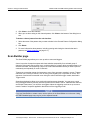
Safety Precautions
The following safety precautions should be observed before using this product and any associated instrumentation. Although
some instruments and accessories would normally be used with non-hazardous voltages, there are situations where hazardous
conditions may be present.
This product is intended for use by qualified personnel who recognize shock hazards and are familiar with the safety precautions
required to avoid possible injury. Read and follow all installation, operation, and maintenance information carefully before using
the product. Refer to the user documentation for complete product specifications.
If the product is used in a manner not specified, the protection provided by the product warranty may be impaired.
The types of product users are:
Responsible body is the individual or group responsible for the use and maintenance of equipment, for ensuring that the
equipment is operated within its specifications and operating limits, and for ensuring that operators are adequately trained.
Operators use the product for its intended function. They must be trained in electrical safety procedures and proper use of the
instrument. They must be protected from electric shock and contact with hazardous live circuits.
Maintenance personnel perform routine procedures on the product to keep it operating properly, for example, setting the line
voltage or replacing consumable materials. Maintenance procedures are described in the user documentation. The procedures
explicitly state if the operator may perform them. Otherwise, they should be performed only by service personnel.
Service personnel are trained to work on live circuits, perform safe installations, and repair products. Only properly trained
service personnel may perform installation and service procedures.
Keithley Instruments products are designed for use with electrical signals that are rated Measurement Category I and
Measurement Category II, as described in the International Electrotechnical Commission (IEC) Standard IEC 60664. Most
measurement, control, and data I/O signals are Measurement Category I and must not be directly connected to mains voltage or
to voltage sources with high transient over-voltages. Measurement Category II connections require protection for high transient
over-voltages often associated with local AC mains connections. Assume all measurement, control, and data I/O connections are
for connection to Category I sources unless otherwise marked or described in the user documentation.
Exercise extreme caution when a shock hazard is present. Lethal voltage may be present on cable connector jacks or test
fixtures. The American National Standards Institute (ANSI) states that a shock hazard exists when voltage levels greater than
30V RMS, 42.4V peak, or 60VDC are present. A good safety practice is to expect that hazardous voltage is present in any
unknown circuit before measuring.
Operators of this product must be protected from electric shock at all times. The responsible body must ensure that operators
are prevented access and/or insulated from every connection point. In some cases, connections must be exposed to potential
human contact. Product operators in these circumstances must be trained to protect themselves from the risk of electric shock. If
the circuit is capable of operating at or above 1000V, no conductive part of the circuit may be exposed.
Do not connect switching cards directly to unlimited power circuits. They are intended to be used with impedance-limited
sources. NEVER connect switching cards directly to AC mains. When connecting sources to switching cards, install protective
devices to limit fault current and voltage to the card.
Before operating an instrument, ensure that the line cord is connected to a properly-grounded power receptacle. Inspect the
connecting cables, test leads, and jumpers for possible wear, cracks, or breaks before each use.
When installing equipment where access to the main power cord is restricted, such as rack mounting, a separate main input
power disconnect device must be provided in close proximity to the equipment and within easy reach of the operator.
For maximum safety, do not touch the product, test cables, or any other instruments while power is applied to the circuit under
test. ALWAYS remove power from the entire test system and discharge any capacitors before: connecting or disconnecting
cables or jumpers, installing or removing switching cards, or making internal changes, such as installing or removing jumpers.
Do not touch any object that could provide a current path to the common side of the circuit under test or power line (earth)
ground. Always make measurements with dry hands while standing on a dry, insulated surface capable of withstanding the
voltage being measured.
The instrument and accessories must be used in accordance with its specifications and operating instructions, or the safety of
the equipment may be impaired.
11/07
Test Equipment Depot - 800.517.8431 - 99 Washington Street Melrose, MA 02176 - TestEquipmentDepot.com
Do not exceed the maximum signal levels of the instruments and accessories, as defined in the specifications and operating
information, and as shown on the instrument or test fixture panels, or switching card.
When fuses are used in a product, replace with the same type and rating for continued protection against fire hazard.
Chassis connections must only be used as shield connections for measuring circuits, NOT as safety earth ground connections.
If you are using a test fixture, keep the lid closed while power is applied to the device under test. Safe operation requires the use
of a lid interlock.
If a
screw is present, connect it to safety earth ground using the wire recommended in the user documentation.
symbol on an instrument means caution, risk of danger. The user should refer to the operating instructions located in
The
the user documentation in all cases where the symbol is marked on the instrument.
symbol on an instrument means caution, risk of danger. Use standard safety precautions to avoid personal contact
The
with these voltages.
The
symbol on an instrument shows that the surface may be hot. Avoid personal contact to prevent burns.
The
symbol indicates a connection terminal to the equipment frame.
If this
symbol is on a product, it indicates that mercury is present in the display lamp. Please note that the lamp must be
properly disposed of according to federal, state, and local laws.
The WARNING heading in the user documentation explains dangers that might result in personal injury or death. Always read
the associated information very carefully before performing the indicated procedure.
The CAUTION heading in the user documentation explains hazards that could damage the instrument. Such damage may
invalidate the warranty.
Instrumentation and accessories shall not be connected to humans.
Before performing any maintenance, disconnect the line cord and all test cables.
To maintain protection from electric shock and fire, replacement components in mains circuits - including the power transformer,
test leads, and input jacks - must be purchased from Keithley Instruments. Standard fuses with applicable national safety
approvals may be used if the rating and type are the same. Other components that are not safety-related may be purchased
from other suppliers as long as they are equivalent to the original component (note that selected parts should be purchased only
through Keithley Instruments to maintain accuracy and functionality of the product). If you are unsure about the applicability of a
replacement component, call a Keithley Instruments office for information.
To clean an instrument, use a damp cloth or mild, water-based cleaner. Clean the exterior of the instrument only. Do not apply
cleaner directly to the instrument or allow liquids to enter or spill on the instrument. Products that consist of a circuit board with
no case or chassis (e.g., a data acquisition board for installation into a computer) should never require cleaning if handled
according to instructions. If the board becomes contaminated and operation is affected, the board should be returned to the
factory for proper cleaning/servicing.
11/07
Test Equipment Depot - 800.517.8431 - 99 Washington Street Melrose, MA 02176 - TestEquipmentDepot.com
Table of Contents
Introduction ................................................................................................................. 1-1
Introduction to this manual................................................................................................... 1-1
Models 707B and 708B applications.................................................................................... 1-1
CD-ROM contents................................................................................................................ 1-2
Using the front-panel interface.................................................................................. 2-1
Introduction .......................................................................................................................... 2-1
Model 707B front panel ........................................................................................................ 2-2
Model 708B front panel ........................................................................................................ 2-2
Keys and navigation wheel .................................................................................................. 2-3
Navigation wheel....................................................................................................................... 2-3
Front-panel keys ....................................................................................................................... 2-4
Display.................................................................................................................................. 2-5
Channel identification................................................................................................................ 2-6
Selecting and closing a channel from the front panel .......................................................... 2-7
Exercise: Select and close slot 1, row C, column 7 crosspoint.................................................. 2-8
Crosspoint display (Model 707B only) ................................................................................. 2-9
Selecting and closing channels using the crosspoint display .................................................. 2-10
Viewing the close or open status of a channel .................................................................. 2-11
Channel patterns................................................................................................................ 2-11
Create a channel pattern......................................................................................................... 2-12
Performing close and open operations on channel patterns ................................................... 2-12
Set up row, column, and channel labels ............................................................................ 2-13
Exercise: Create a row label for row D using the front panel .................................................. 2-14
Using the web interface.............................................................................................. 3-1
Introduction .......................................................................................................................... 3-1
Connect to the instrument web interface ............................................................................. 3-1
Web interface home page.................................................................................................... 3-2
Log in to the instrument........................................................................................................ 3-2
Card pages........................................................................................................................... 3-3
Open and close channels from the card pages ......................................................................... 3-4
Set up channel patterns from the web interface ........................................................................ 3-6
Scan Builder page................................................................................................................ 3-8
Create a scan list ...................................................................................................................... 3-9
Run the scan ............................................................................................................................. 3-9
Stop the scan .......................................................................................................................... 3-10
Clear the scan list from the web interface ............................................................................... 3-10
Set up simple triggers ............................................................................................................. 3-10
Test Equipment Depot - 800.517.8431 - 99 Washington Street Melrose, MA 02176 - TestEquipmentDepot.com
Table of Contents
Models 707B and 708B Switching Matrix User's Manual
TSB Embedded.................................................................................................................. 3-11
Create a script using TSB Embedded ..................................................................................... 3-11
Working with the Model 4200-SCS ............................................................................ 4-1
Introduction .......................................................................................................................... 4-1
Equipment required to run the example............................................................................... 4-1
Configure Model 707B or 708B for Model 4200-SCS.......................................................... 4-1
Add Model 707B or 708B to Model 4200-SCS .................................................................... 4-2
Next steps ............................................................................................................................ 4-3
Working with the Series 2600A.................................................................................. 5-1
About the Series 2600A examples....................................................................................... 5-1
Equipment required to run the examples ............................................................................. 5-2
Connect the equipment ........................................................................................................ 5-2
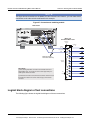
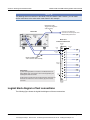
Logical block diagram of test connections ........................................................................... 5-3
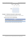
Example 1: Control with separate interfaces ....................................................................... 5-4
Set up communication............................................................................................................... 5-4
Example program code for the Model 707B or 708B ................................................................ 5-5
Example program code for the Model 2635 .............................................................................. 5-5
Example code to run the test..................................................................................................... 5-6
Example 2: Using TSP-Link to configure instruments ......................................................... 5-7
Set up communication............................................................................................................... 5-8
Example program code ............................................................................................................. 5-9
Example code to run the test................................................................................................... 5-10
Example 3: Configure using TSP-Link and interactive triggers ......................................... 5-12
Set up communication............................................................................................................. 5-12
Example program code ........................................................................................................... 5-13
Example program code to run the test .................................................................................... 5-16
Example 4: Using the scanning and triggering model ....................................................... 5-17
Set up communication............................................................................................................. 5-17
Example program code ........................................................................................................... 5-17
Example program code to run the test .................................................................................... 5-20
Using background scans for longer scan lists ......................................................................... 5-21
Working with the Series 2400 .................................................................................... 6-1
About the Series 2400 examples ......................................................................................... 6-1
Equipment required to run the examples ............................................................................. 6-1
Connect the equipment ........................................................................................................ 6-1
Logical block diagram of test connections ........................................................................... 6-2
Example 1: Individual commands for switch-measure......................................................... 6-3
Example program code for the Model 2400 .............................................................................. 6-3
Example program code for the Model 707B or 708B ................................................................ 6-4
Example 2: Digital I/O triggering for switch-measure synchronization ................................ 6-5
ii
707B-900-01 Rev. A / August 2010
Test Equipment Depot - 800.517.8431 - 99 Washington Street Melrose, MA 02176 - TestEquipmentDepot.com
Models 707B and 708B Switching Matrix User's Manual
Table of Contents
Example program code for the Model 2400 .............................................................................. 6-5
Example program code for the Model 707B or 708B ................................................................ 6-6
Overview of running the test...................................................................................................... 6-9
Example code to run the test..................................................................................................... 6-9
Troubleshooting FAQs ............................................................................................... 7-1
About this section................................................................................................................. 7-1
Need different line frequency or voltage .............................................................................. 7-1
Model 4200-SCS does not recognize switch matrix ............................................................ 7-1
"A" model software does not run on "B" models .................................................................. 7-3
Matrix Ready and External Trigger lines.............................................................................. 7-3
Switch matrix does not recognize my card .......................................................................... 7-3
Instrument's internal web page is not accessible................................................................. 7-4
Error when I try to close a channel ...................................................................................... 7-5
Switch relays will not close .................................................................................................. 7-5
Save the present state of the instrument ............................................................................. 7-5
LabVIEW driver for the Model 707B or 708B....................................................................... 7-6
Next steps.................................................................................................................... 8-1
Index....................................................................................................................Index-1
707B-900-01 Rev. A / August 2010
Test Equipment Depot - 800.517.8431 - 99 Washington Street Melrose, MA 02176 - TestEquipmentDepot.com
iii
Test Equipment Depot - 800.517.8431 - 99 Washington Street Melrose, MA 02176 - TestEquipmentDepot.com
Section 1
Introduction
In this section:
Introduction to this manual ......................................... 1-1
Models 707B and 708B applications .......................... 1-1
CD-ROM contents...................................................... 1-2
Introduction to this manual
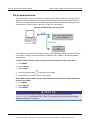
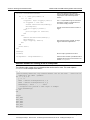
The purpose of this manual is to provide detailed tutorials to help you achieve success with your
Keithley Instruments Model 707B or 708B Semiconductor Switching Matrix. The basics of the two
simplest interfaces, the front panel and the web interface, are provided to familiarize you with the
instrument. The tutorials build upon one another, so we recommend that you read this manual from
Section 1 to the end of Section 3. Select and run all examples in Sections 4, 5, and 6 that are relevant
to your intended use and to the equipment you are using.
Some of the examples in this manual may use unfamiliar commands and concepts. For detailed
information about these, refer to the Models 707B and 708B Reference Manual (part number
707B-901-01) on the Product Information CD-ROM that came with your instrument.
Models 707B and 708B applications
Unlike a standalone instrument, the Keithley Instruments Models 707B and 708B are switching
systems that are used to intelligently connect other instruments to multiple devices. This manual
provides application examples that guide you through several common instrument-to-device switching
scenarios. These applications are presented after the summary information about the switching
matrix, and include:
•
Working with the Model 4200-SCS (on page 4-1): Demonstrates how to connect the Keithley
Instruments Model 4200 Semiconductor Characterization System to a Model 707B or 708B. This
enables the Model 4200-SCS to automate measurements to multiple devices for DC, C-V, and
pulsed I-V characterization.
•
Working with the Series 2600A (on page 5-1): Demonstrates how to use the Model 707B or 708B
with a Keithley Instruments Series 2600A System SourceMeter® instrument to perform an I-V
sweep across a diode.
•
Working with the Series 2400 (on page 6-1): Demonstrates the basic interaction of the Model
707B or 708B with a Keithley Instruments Model 2400 SourceMeter instrument, including how to
use digital I/O triggering to synchronize source and measure actions between the Model 707B or
708B and the Model 2400. The concepts in these examples can be applied when used using the
Model 707B or 708B with other SCPI-based instruments.
Test Equipment Depot - 800.517.8431 - 99 Washington Street Melrose, MA 02176 - TestEquipmentDepot.com
Section 1: Introduction
Models 707B and 708B Switching Matrix User's Manual
CD-ROM contents
There are several CD-ROMs that are included with your instrument, which contain the following items:
•
The Test Script Builder Software and the Model 707B or 708B TSB add-in, which is a software
tool you can use to create, modify, debug, and store test script processor (TSP®) test scripts
•
Switching product information
•
Product documentation, including PDFs of the Model 707B or 708B Quick Start Guide, User
Manual, and Reference Manual, as well as the product data sheet, product specifications, and
rack-mount kit instructions
•
Product documentation for the switch cards that are compatible with the Model 707B or 708B
•
Model 707B or 708B drivers for IVI Instrument Driver and driver for National Instrument’s
LabVIEW® and related release notes
•
J2SETM Runtime Environment, which is necessary to use the instrument's web interface
•
Keithley I/O layer and release notes, including necessary drivers for communication over the USB
interface (see the Models 707B and 708B Reference Manual for details on using the USB
interface).
For the latest drivers and additional support information, see the Keithley Instruments support website
(http://www.keithley.com/support).
1-2
707B-900-01 Rev. A / August 2010
Test Equipment Depot - 800.517.8431 - 99 Washington Street Melrose, MA 02176 - TestEquipmentDepot.com
Section 2
Using the front-panel interface
In this section:
Introduction ................................................................ 2-1
Model 707B front panel .............................................. 2-2
Model 708B front panel .............................................. 2-2
Keys and navigation wheel......................................... 2-3
Display ....................................................................... 2-5
Selecting and closing a channel from the front panel. 2-7
Crosspoint display (Model 707B only) ........................ 2-9
Viewing the close or open status of a channel ......... 2-11
Channel patterns...................................................... 2-11
Set up row, column, and channel labels................... 2-13
Introduction
Before starting this section, complete the tasks outlined in the Models 707B and 708B Quick Start
Guide and install a switch card within the switching matrix. Once you have completed those tasks,
read this section, which provides enough basic information about the Models 707B and 708B
front-panel interfaces to work through the examples provided in this manual.
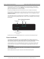
The front panel of the Keithley Instruments Model 707B or 708B contains the following items:
•
The display
•
The crosspoint display (Model 707B only)
•
The keys and navigation wheel
•
The LAN STATUS light
•
The POWER button
You can use the keys, displays, and the navigation wheel
to change the selected channel or
channel pattern. You can also use them to access, view, and edit the menu items. The crosspoint
display on the Model 707B shows you which channels are opened and closed.
For additional information about the front panel, see the "Front-panel operation" section in the Models
707B and 708B Reference Manual.
Test Equipment Depot - 800.517.8431 - 99 Washington Street Melrose, MA 02176 - TestEquipmentDepot.com
Section 2: Using the front-panel interface
Models 707B and 708B Switching Matrix User's Manual
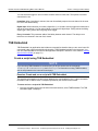
Model 707B front panel
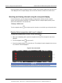
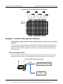
The front panel of the Model 707B is shown below.
Figure 1: Model 707B front panel
12
11
09
10
08
07
06
05
04
02
Channel columns
03
01
707B SWITCHING MATRIX
2A
Slot and
channel rows
2B
SLOT 1
2C
SLOT 2
2D
SLOT 3
SLOT 4
2E
Slot
information
SLOT 5
2F
SLOT 6
2G
2H
2A+01
LAN STATUS
CLS: 2C04
DISPLAY
CONFIG
POWER
Display
Instrument
power button
Change
screen
display
Change scan
and channel attributes
Navigation
wheel
Model 708B front panel
The front panel of the Model 708B is shown below.
2-2
707B-900-01 Rev. A / August 2010
Test Equipment Depot - 800.517.8431 - 99 Washington Street Melrose, MA 02176 - TestEquipmentDepot.com
Models 707B and 708B Switching Matrix User's Manual
Section 2: Using the front-panel interface
Figure 2: Model 708B front panel
LAN
KEITHLEY
708B SWITCHING MATRIX
MODEL 708B
DISPLAY
POWER
CONFIG
Display
Change Change scan
Instrument
screen and channel
power button displays attributes
Navigation
wheel
Keys and navigation wheel
The keys and navigation wheel
instrument from the front panel.
on the front panel allow you to turn on, set up, and operate the
The POWER key. Press this key to turn the instrument on (|). Press it again to turn the instrument off
(0).
Navigation wheel
Turn the navigation wheel
to scroll to a menu option or to change the selected value.
Push the navigation wheel
to open menus or to select a menu option or a value. In most cases,
pressing the navigation wheel
performs the same action as pressing the ENTER key.
to control which slot is displayed on the
On the Model 707B, you can use the navigation wheel
crosspoint display.
To change a value with multiple characters:
1. Turn the navigation wheel
when selected).
2. Press the navigation wheel
3. Turn the navigation wheel
4. Press the navigation wheel
to go to the character you want to change (the character blinks
to edit that character.
to change the value.
to keep the change.
5. Repeat these steps as needed to change the value.
6. Press the ENTER key or the navigation wheel
when finished changing all the characters.
707B-900-01 Rev. A / August 2010
Test Equipment Depot - 800.517.8431 - 99 Washington Street Melrose, MA 02176 - TestEquipmentDepot.com
2-3
Section 2: Using the front-panel interface
Models 707B and 708B Switching Matrix User's Manual
Front-panel keys
The DISPLAY key cycles between three screens: The channel display or pattern display, the closed
channel list, and the user screen text, which is set with display.settext().
When the closed channel listing is displayed, if the list of channels is longer than one screen, you can
use the navigation wheel
to scroll though the list of closed channels.
The CONFIG key accesses attribute menus in which you can configure channels and scans.
CONFIG and then CHAN opens the Channel Attribute Menu.
CONFIG and then SCAN opens the Scan Attribute Menu.
The top row of keys under the display allows you to open and close channels, work with scan lists,
and load and run scripts.
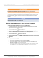
Figure 3: Models 707B and 708B top row of keys
Key descriptions
Key
Description
OPEN ALL
Opens all closed channels.
STEP
If a scan list has been defined, press STEP to step through the list.
Each press is one scan step. See Working with scan lists from the
front panel.
OPEN
Opens the selected channel or channel pattern.
CLOSE
Closes the selected channel or channel pattern.
LOAD
Loads code or scripts that can be run from the front panel.
RUN
Runs the last code or script selected through the LOAD key.
INS
Appends the selected channel or channel pattern to the scan list.
DEL
Deletes the first occurrence of the selected channel or channel
pattern from the scan list.
The bottom row of keys allow you access menus and set up channels, patterns, cards, scans,
triggers, and general instrument operation.
Figure 4: Bottom row of keys
2-4
707B-900-01 Rev. A / August 2010
Test Equipment Depot - 800.517.8431 - 99 Washington Street Melrose, MA 02176 - TestEquipmentDepot.com
Models 707B and 708B Switching Matrix User's Manual
Section 2: Using the front-panel interface
Key descriptions
Key
Description
CHAN
If a channel is displayed, opens the Channel Action Menu options, which allows you to open
and close channels. If a pattern is displayed, pressing CHAN switches to channel view.
PATT
If a pattern is displayed, opens the Pattern Action Menu options, which allows you to
manage patterns, open and close patterns, and reset them. If a channel is displayed,
pressing PATT changes to display a pattern.
SLOT
Displays information about the installed cards and the instrument. Information includes the
firmware revision, model name, and model number.
SCAN
Opens the Scan Action Menu options, which allows you to run, manage, view, and reset
scan lists. See Scanning and triggering.
TRIG
Generates a trigger that can be used in a script or the trigger model. See Scanning and
triggering.
MENU
Opens the Main Menu options, which allows you to manage scripts, manage
communications, select channel connections, test the keys, test the display, manage digital
I/O settings, set up the beeper, and display instrument information.
EXIT
This key:
ENTER
•
Cancels the current selection and returns to the previous menu item.
•
Exit remote operation so you can control the instrument from the front panel.
•
Aborts a scan that is running.
•
Aborts a script that is executing.
Accepts the current selection or brings up the next menu option. In most cases, pressing
ENTER is the same as pressing the navigation wheel
.
LAN status light
The LAN Status light is lit when the instrument is connected through the local area network (LAN) with
no errors.
If this is not lit, the instrument is not connected through the LAN or there is a connection problem.
If you are using the web interface, the LAN Status light blinks when you click ID.
See the "LAN communication interface" topic in the Models 707B and 708B Reference Manual for
more information.
Display
NOTE
This section describes the front-panel display of the Model 708B and the bottom display of the Model
707B.
707B-900-01 Rev. A / August 2010
Test Equipment Depot - 800.517.8431 - 99 Washington Street Melrose, MA 02176 - TestEquipmentDepot.com
2-5
Section 2: Using the front-panel interface
Models 707B and 708B Switching Matrix User's Manual
During operation, the display provides information about the selected channel, channel pattern,
channel state, and errors. You can press DISPLAY to cycle between the display of the channel or
pattern, the closed channel list, or a screen message.
During setup, the display shows menu choices that you can use to configure the instrument.
During operation, the display shows the control status (local or remote) and the current channel, and
indicates if any channels are closed. An example is shown below. If REM is not displayed, control is
through the front panel.
The control status is shown in the upper left corner of the display. If REM is displayed, the instrument
is being controlled remotely (through GPIB, LAN, or USB). If REM is not displayed, control is through
the front panel.
Figure 5: Display during operation
Remote control
indicator
Slot and row
Column
REM
2A+01
CLS:1A01
Closed channels
(<none> if no channels
are closed)
By default, the top line of the display shows the slot, row, and column of the selected channel.
Channel identification
The channels on the cards that you can use with the Model 707B or 708B are referred to by a
channel specifier. The specifier is used to identify channels for use with close and open operations,
scans, and channel patterns, using the front panel, web, or remote command interface.
A channel specifier is a four or five-digit alphanumeric sequence. The first digit is always the slot
number of the card in the mainframe. The remaining digits vary depending on the type of card.
Channel types
The Models 707B and 708B support matrix cards. The documentation for your specific card model
lists the available channels.
Specify multiple channels using lists. Lists build on the individual channel specifier.
2-6
707B-900-01 Rev. A / August 2010
Test Equipment Depot - 800.517.8431 - 99 Washington Street Melrose, MA 02176 - TestEquipmentDepot.com
Models 707B and 708B Switching Matrix User's Manual
Section 2: Using the front-panel interface
Channel identifiers
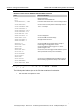
The channels on the matrix cards are referred to by their slot, bank, row, and column numbers:
•
Slot number: The number of the slot in which the card is installed.
•
Bank: The bank number, if used by your card. See your card documentation.
•
Row number: The row number is either 1 to 8 or A to Z. See your card documentation.
•
Column number: Always two digits. For columns greater than 99, use A, B, C and so on to
represent 10, 11, 12, …; the resulting counting sequence is: 98, 99, A0, A1, …, A8, A9, B0,
B1, …
Matrix channel examples
Reference
Slot
Bank
Row
Column
1A05
1
N/A
1
05
1C05
1
N/A
3
05
3C12
3
N/A
3
12
Figure 6: Matrix card display showing channel identifier
Matrix Card
Slot 2, Row 1, Column 01
2A+01
Status
CLS: 2c04
OPN = Open
CLS = Closed
LOAD
RUN
INS
DEL
DISPLAY
TRIG
MENU
EXIT ENTER
CONFIG
Selecting and closing a channel from the front panel
NOTE
For the Model 707B, also see Selecting and closing channels using the crosspoint display (on page 210) to select a channel using the crosspoint display.
707B-900-01 Rev. A / August 2010
Test Equipment Depot - 800.517.8431 - 99 Washington Street Melrose, MA 02176 - TestEquipmentDepot.com
2-7
Section 2: Using the front-panel interface
Models 707B and 708B Switching Matrix User's Manual
CAUTION
Hot switching can dry weld reed relays such that they will always be on. Hot switching is
recommended only when external protection is provided.
You can perform operations on a single channel from the front panel. To select a channel, you use
the navigation wheel
operation.
. Once a channel is selected, it is the selected channel for front panel
NOTE
If labels are assigned to your rows and columns, you will see those labels instead of the four-digit
channel specifiers referred to in the following text.
Exercise: Select and close slot 1, row C, column 7 crosspoint
To select and close the crosspoint on slot 1, at row C and column 7:
1. To change the present row, press the navigation wheel. The first two digits of the four-digit
channel specifier flash, indicating edit mode.
2. Turn the navigation wheel
change the digit to 1C.
3. Press the navigation wheel
. This accepts the row selection and selects edit mode for the
column. The last two digits of the channel specifier flash, indicating edit mode.
4. Turn the navigation wheel
5. Press the navigation wheel
main display.
to change the digits to 07.
or ENTER to accept the channel, exit edit mode, and return to the
6. To:
2-8
•
Open the channel: Press OPEN.
•
Close a channel without affecting any other channels: Select CLOSE.
•
Close a channel and open any other closed channels on the instrument: Select CHAN and select
EXCLOSE. Press ENTER to close the selected channels.
•
Close a channel and open any other closed channels on the slot that contains the selected channel:
Select CHAN, and then select EXSLOTCLOSE. Press ENTER to close the selected channels.
707B-900-01 Rev. A / August 2010
Test Equipment Depot - 800.517.8431 - 99 Washington Street Melrose, MA 02176 - TestEquipmentDepot.com
Models 707B and 708B Switching Matrix User's Manual
Section 2: Using the front-panel interface
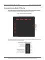
Crosspoint display (Model 707B only)
The crosspoint display on the front panel of the Model 707B displays information about the slots that
contain cards and the open and closed state of the channels. for one card slot at a time. If there are
no cards in the instrument's slots, the crosspoint display shows "No card in unit."
Figure 7: Model 707B crosspoint display
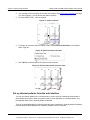
The crosspoint display has a list of slots on the right. To the left of the slot list are lights that show you
an overview of the cards in the instrument's slots.
Figure 8: Model 707B slot indicators
Red lights are lit
if a channel is
closed in that slot
SLOT 1
SLOT 2
SLOT 3
Yellow lights are lit when
the slot contains a card.
The bright light shows
which slot is displayed
on the crosspoint display
SLOT 4
SLOT 5
SLOT 6
707B-900-01 Rev. A / August 2010
Test Equipment Depot - 800.517.8431 - 99 Washington Street Melrose, MA 02176 - TestEquipmentDepot.com
2-9
Section 2: Using the front-panel interface
Models 707B and 708B Switching Matrix User's Manual
In the figure above, there are cards in five slots, no card in slot 5, and the channels for the card in slot
3 are displayed on the crosspoint display. Also, at least one channel is closed on the card in slot 2.
Selecting and closing channels using the crosspoint display
From the front panel, you can change the display to show another card slot, choose a specific
channel, and open and close channels. For the Model 707B, the crosspoint display shows you the
status of the channels for one card at a time.
To display a different slot:
Turn the navigation wheel
to the right to go to the next slot, or to the left to go to the previous slot.
Exercise: Select crosspoint on slot 2, row C, column 3
To select the crosspoint that is on slot 2, at row C and column 3
1. When you are displaying slot 2, press the navigation wheel
displayed.
2. Turn the navigation wheel
. The red lights for that slot are
to go to row 2C.
3. Press the navigation wheel
to select the row. The red lights for each crosspoint in the row are
on, as shown in the following figure.
Figure 9: One row selected
2B
SLOT 1
2C
SLOT 2
SLOT 3
2D
NOTE
On the Model 707B, if you scroll past the last row of any slot, you will go to the next slot.
2-10
707B-900-01 Rev. A / August 2010
Test Equipment Depot - 800.517.8431 - 99 Washington Street Melrose, MA 02176 - TestEquipmentDepot.com
Models 707B and 708B Switching Matrix User's Manual
Section 2: Using the front-panel interface
4. After choosing the row, press the navigation wheel
. A column of red lights is displayed.
5. Turn the navigation wheel
to go to column 03. Note that scrolling through the columns will not
scroll through slots as scrolling through rows does.
or ENTER to select the column and row. This channel is now
6. Press the navigation wheel
displayed on the bottom display as 2C+03.
7. To:
•
Open the channel: Press OPEN.
•
Close a channel without affecting any other channels: Select CLOSE.
•
Close a channel and open any other closed channels on the instrument: Select CHAN and select
EXCLOSE. Press ENTER to close the selected channels.
•
Close a channel and open any other closed channels on the slot that contains the selected channel:
Select CHAN, and then select EXSLOTCLOSE. Press ENTER to close the selected channels.
Viewing the close or open status of a channel
Closed channels are shown separated by commas after the CLS: characters on the display of the
instrument. If no channels are closed, <none> is displayed here. If the list of closed channels extends
past one screen, ... is displayed at the end of the line. Press DISPLAY to display the full list of
closed channels. Use the navigation wheel
DISPLAY twice to return to the main display.
to scroll through the list. After viewing the list, press
Figure 10: Multiple closed channels
2A+01
CLS: 1A01,1A02,1A03,1A05,1A09,...
Channel patterns
You can use channel patterns as a convenient way to refer to a group of switching channels with a
single alphanumeric name. When you perform close or open operations on a channel pattern, only
the channels that are in the channel pattern are affected.
There is no speed advantage in performing close and open operations on channel patterns compared
to performing the same operations on individual channels or a list of channels.
707B-900-01 Rev. A / August 2010
Test Equipment Depot - 800.517.8431 - 99 Washington Street Melrose, MA 02176 - TestEquipmentDepot.com
2-11
Section 2: Using the front-panel interface
Models 707B and 708B Switching Matrix User's Manual
Create a channel pattern
When you create a channel pattern, make sure to:
•
Include all of the channels that are needed for that channel pattern.
•
Check that channels contained in the pattern are correct.
•
Check that channels contained in the pattern create the desired path connection.
•
Make sure that channels that you want to include in the pattern are not set to forbidden to close.
When naming the channel pattern, be aware:
•
The first character of the name must be alphabetic (upper or lower case)
•
Names are case sensitive
•
Pattern names must be different than row, column, and channel labels
Exercise: Create channel pattern "TEST01" from closed channels
To create channel pattern "TEST01" from channels currently closed:
1. Close the channels you want to include in the channel pattern. For this example, close channels
"1A01," "1B02," and "1C03." Refer to Selecting and closing a channel from the front panel (on
page 2-7) for instructions on how to close individual channels.
2. Press the PATT key.
3. From this menu, select the CREATE menu item.
4. From this menu, select the SNAPSHOT menu item.
5. At the prompt, enter a pattern name using the navigation wheel. For this example, enter the name
TEST01. Use the navigation wheel to select each character of the name.
6. Use the ENTER key to apply the selection.
7. Use the EXIT key to leave the menu.
NOTE
Refer to "Channel patterns" in the Models 707B and 708B Reference Manual for more details.
Performing close and open operations on channel patterns
WARNING
Careless channel pattern operation could create an electric shock hazard that could result in
severe injury or death. Improper operation can also cause damage to the switching cards and
external circuitry. The control of multiple channels using channel patterns should be
restricted to experienced test engineers who recognize the dangers associated with multiple
channel closures.
2-12
707B-900-01 Rev. A / August 2010
Test Equipment Depot - 800.517.8431 - 99 Washington Street Melrose, MA 02176 - TestEquipmentDepot.com
Models 707B and 708B Switching Matrix User's Manual
Section 2: Using the front-panel interface
You can close and open channel patterns the same way you do for individual channels.
When you request a close or open operation, the Model 707B or 708B verifies that the channels exist
for a pattern, but does not verify that the switch path connection is correct. You must ensure the
requested operation is safe for a channel pattern and that a good connection will result for your
application with the channel pattern.
Exercise: Close channel pattern "TEST01" from the front panel
To close channel pattern "TEST01" from the front panel:
1. Press the PATT key to display a channel pattern.
2. Use the navigation wheel to select "TEST01," the channel pattern you want to close.
Model 707B only: Note that when you select a pattern, on the crosspoint display, the lights for
the channels included in the pattern are dimly lit.
3. Perform any of the following actions:
•
Open the channels in the channel pattern: Press OPEN.
•
Close the channels in the channel pattern without affecting any other channels: Press CLOSE.
•
Close the channels in the channel pattern and open any other closed channels on the instrument:
Select PATT and select EXCLOSE. Press ENTER to open or close the channels.
•
Close the channels in the channel pattern and open any other closed channels on the slot: Press PATT
and select EXSLOTCLOSE. Press ENTER to open or close the channels.
Set up row, column, and channel labels
You can define labels for rows, columns, and channels. Using labels is a more descriptive way to
refer to switching paths than the default channel identifiers.
Labels must be unique; they cannot have the same as the name of another row, column, channel, or
channel pattern. Labels cannot contain spaces, and they do not persist through a power cycle.
Channel labels can be up to 19 characters. Row and columns labels can be up to 8 characters. On
the crosspoint display, the first four characters of the label are displayed. On the bottom display, the
full label is displayed.
You can only set labels for slots and channels that are installed in the instrument.
707B-900-01 Rev. A / August 2010
Test Equipment Depot - 800.517.8431 - 99 Washington Street Melrose, MA 02176 - TestEquipmentDepot.com
2-13
Section 2: Using the front-panel interface
Models 707B and 708B Switching Matrix User's Manual
Exercise: Create a row label for row D using the front panel
To create a row label for row D using the front panel:
1. If a pattern name is currently displayed on the bottom display, press CHAN to place the display in
Channel view.
2. Use the navigation wheel to select any channel on row D. For example, select "1D01."
3. Press CONFIG, then press CHAN.
4. Use the navigation wheel
are defined as:
to select LABEL-ROW to define a row label. The label selections
•
LABEL: Sets the label that is displayed on the front panel for the specified crosspoint.
•
LABEL-ROW: Sets the label that is displayed on the front panel for the specified row.
•
LABEL-COL: Sets the label that is displayed on the front panel for the specified column.
5. Change the row label to "SMU1" using the navigation wheel
6. Press the navigation wheel
to change each character.
or ENTER to save the change.
7. Press EXIT to return to the main display.
The bottom display will now use "SMU1" to refer to row D on slot 1. For example, selecting crosspoint
"1D03" prints "SMU1+03" to the bottom display. Additionally, the crosspoint display on the Model
707B updates to use the new row label.
Quick Tip
The exercise, "Create a script using TSB embedded," shows setting up labels using the remote
interface and TSB Embedded.
2-14
707B-900-01 Rev. A / August 2010
Test Equipment Depot - 800.517.8431 - 99 Washington Street Melrose, MA 02176 - TestEquipmentDepot.com
Section 3
Using the web interface
In this section:
Introduction ................................................................ 3-1
Connect to the instrument web interface .................... 3-1
Web interface home page .......................................... 3-2
Log in to the instrument.............................................. 3-2
Card pages................................................................. 3-3
Scan Builder page...................................................... 3-8
TSB Embedded........................................................ 3-11
Introduction
The Model 707B or 708B web interface allows you to review instrument status, control the instrument,
and upgrade the instrument over a LAN connection.
The instrument web page resides in the firmware of the instrument. Changes you make through the
web interface are immediately made in the instrument.
Many examples in this manual and in the Model 707B and 708B Reference Manual can be run
through the TSB Embedded page of the instrument web interface.
Connect to the instrument web interface
The web interface requires the web browser plug-in Sun Java Runtime Environment Version 6 or
higher. Installation files are available from http://www.java.com/en/download/manual.jsp. Installation
files are also available on the Models 707B and 708B Product Information CD-ROM that came with
your instrument. Install the J2SE software.
The ActiveX control and Java applets are installed from the instrument but, depending on the browser
security settings, they may require the users permission to be downloaded and installed.
To connect to the instrument web interface, you must have an LAN connection from the computer to
the instrument. See "LAN communications" in the Model 707B and 708B Reference Manual. Follow
the instructions under the heading, "LAN quick start."
An alternative to the LXI Discovery Tool is to follow the instructions below to connect to the
instrument:
1. Confirm the LAN light on the instrument is illuminated.
Test Equipment Depot - 800.517.8431 - 99 Washington Street Melrose, MA 02176 - TestEquipmentDepot.com
Section 3: Using the web interface
Models 707B and 708B Switching Matrix User's Manual
2. Open an Internet browser, such as Windows Internet Explorer (v6.0 or higher only).
3. In the Address box, enter the IP address of the instrument (to find the IP address, from the front
panel of the instrument, select MENU > LAN > STATUS > IP-ADDRESS).
The home page of the instrument web interface is displayed.
Web interface home page
The home page of the instrument web interface gives you basic information about the instrument,
including:
•
The model, serial number, firmware revision, raw socket, and LXI information
•
A list of slots and the switch cards installed in each slot
•
An ID button to help you locate the instrument
Log in to the instrument
The web interface has both interactive and read-only pages. These pages are always listed in the
navigation panel on the left side of the web interface.You can review information on any of the pages
without logging in, but to change information, you must log in.
Pages that contain information you can change include a Login button. You must be logged in to
complete the exercises in this section. Once you have logged in to one page of the web interface, you
do not need to log in again unless you reload the page.
To log into the instrument:
1. Open a page that contains a Login button, such as one of the Cards pages, Scan Builder, or TSB
Embedded.
2. Click Login. The login dialog box is displayed.
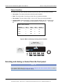
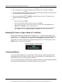
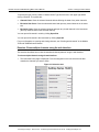
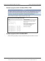
Figure 11: Log in
3-2
707B-900-01 Rev. A / August 2010
Test Equipment Depot - 800.517.8431 - 99 Washington Street Melrose, MA 02176 - TestEquipmentDepot.com
Models 707B and 708B Switching Matrix User's Manual
Section 3: Using the web interface
3. Enter the password (the default is admin).
Figure 12: Enter password
4. Click Login.
NOTE
The default password is admin. If the password has been changed, it is available from the front panel
of the instrument. Press MENU > LAN > STATUS > PASSWORD.
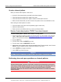
Card pages
The card pages are interactive pages where you can work with channels in each slot.
To open a card page, on the left navigation, click the slot number.
There is a specific page for each card installed in the mainframe. This page displays a grid that shows
the relay configuration of the switch card.
707B-900-01 Rev. A / August 2010
Test Equipment Depot - 800.517.8431 - 99 Washington Street Melrose, MA 02176 - TestEquipmentDepot.com
3-3
Section 3: Using the web interface
Models 707B and 708B Switching Matrix User's Manual
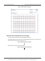
Figure 13: Web interface Cards page
Open and close channels from the card pages
You can open and close channels from the card pages in several ways.
The simplest method is to click a connection. The channel changes state to open or closed. When the
channel is open, the connection is a circle with an x in it:
Figure 14: Web interface open channel
When the channel is closed, the connection is black:
Figure 15: Web interface closed channel
3-4
707B-900-01 Rev. A / August 2010
Test Equipment Depot - 800.517.8431 - 99 Washington Street Melrose, MA 02176 - TestEquipmentDepot.com
Models 707B and 708B Switching Matrix User's Manual
Section 3: Using the web interface
To specify the type of close, select a Channel Action Type from the box in the upper right before
closing a channel. The options are:
•
Channel Close: Close the selected channel without affecting the state of any other channels.
•
Exclusive Slot Close: Close the selected channel and open any closed channels in the same
slot.
•
Exclusive Close: Close the selected channel and open any closed channels in the instrument
(the only closed channel is the selected channel).
You can open all channels in a slot by clicking Open Slot.
You can open all channels in the instrument by clicking Open All.
For more information on opening and closing channels, see "Working with channels" in the Models
707B and 708B Reference Manual.
Exercise: Close multiple channels using the web interface
This exercise describes how to close channels and channel patterns using the web interface.
To close multiple channels using the web interface:
1. The instrument home page is displayed. From the navigation on the left, select the slot that
contains the channels you want to close.
Figure 16: Select the slot
707B-900-01 Rev. A / August 2010
Test Equipment Depot - 800.517.8431 - 99 Washington Street Melrose, MA 02176 - TestEquipmentDepot.com
3-5
Section 3: Using the web interface
Models 707B and 708B Switching Matrix User's Manual
2. You must log into the instrument to work with the channels. See Log in to the instrument (on page
3-2). After logging in, you can access the channel controls.
3. To close channel "1A01," click the channel.
Figure 17: Close a channel
4. To perform an exclusive close on channel "1A02," select Exclusive Slot Close in the Channel
Action Type box.
Figure 18: Select exclusive slot close
5. Click 1A02 to close that channel and open all other channels.
Figure 19: Close a channel with exclusive close
Set up channel patterns from the web interface
You can use channel patterns as a convenient way to refer to a group of switching channels with a
single alphanumeric name. When you perform close or open operations on a channel pattern, only
the channels that are in the channel pattern are affected.
There is no speed advantage in performing close and open operations on channel patterns compared
to performing the same operations on individual channels or a list of channels.
3-6
707B-900-01 Rev. A / August 2010
Test Equipment Depot - 800.517.8431 - 99 Washington Street Melrose, MA 02176 - TestEquipmentDepot.com
Models 707B and 708B Switching Matrix User's Manual
Section 3: Using the web interface
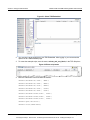
Exercise: Create channel pattern "TEST02" using the Snapshot feature
To create a channel pattern "TEST02" from the web interface using the Snapshot feature:
1. From the left navigation, click slot 1.
2. Close the channels that you want to include in the pattern. For this example, close channels
1D12, 1C11, 1B10, and 1A09.
3. Click Pattern (above the Channel Action Type box). The Channel Pattern Configuration dialog
box is displayed.
4. Type TEST02 for the pattern name in the box at the top of the dialog box.
5. Click Snapshot. A new pattern is created that contains the closed channels.
Figure 20: Channel pattern configuration dialog box
Exercise: Close channels in "TEST02" from the web interface
To close channels in channel pattern "TEST02" from the web interface:
1. Click Pattern (above the Channel Action Type box). The Channel Pattern Configuration dialog
box is displayed.
2. Select TEST02 from the list box at the top of the dialog box.
3. In the Actions area, select the type of close you want to perform.
707B-900-01 Rev. A / August 2010
Test Equipment Depot - 800.517.8431 - 99 Washington Street Melrose, MA 02176 - TestEquipmentDepot.com
3-7
Section 3: Using the web interface
Models 707B and 708B Switching Matrix User's Manual
4. Click Close to close the channels.
5. When you are done acting on this channel pattern, click Close at the bottom of the dialog box to
exit.
To delete a channel pattern from the web interface:
1. Select the name of the pattern that you want to delete in the Channel Pattern Configuration dialog
box.
2. Click Delete.
3. For more information about patterns, including opening and closing the channels that are in
patterns, see Channel patterns (on page 2-11).
Scan Builder page
The Scan Builder page allows you to set up and run scans and triggers.
A scan is a series of steps that opens and closes switches sequentially for a selected group of
channels. During each step, actions occur, such as waiting for a trigger, taking a measurement on an
external instrument, and completing a step count. Scans automate actions that you want to perform
consistently and repeatedly on a set of channels.
Triggers are events that prompt the instrument to move from one step to another in a scan. Triggers
can come from a variety of sources, such as a key press, digital input, or expiration of a timer. The
sequence of actions and events that occur during the scan is called the trigger model, described in
Trigger model.
Scanning and triggering allow you to synchronize actions across channels. You can set up a scan
using the trigger model to precisely time and synchronize the Model 707B or 708B between channels
and multiple instruments. You can also use triggers without the triggering model to set up a scan to
meet the needs of a specific application that does not fit the triggering model.
NOTE
If you use Scan Builder to create a scan, use the options in the Scan Builder to run the scan. Using
the TSB Embedded page may not give you the expected results.
3-8
707B-900-01 Rev. A / August 2010
Test Equipment Depot - 800.517.8431 - 99 Washington Street Melrose, MA 02176 - TestEquipmentDepot.com
Models 707B and 708B Switching Matrix User's Manual
Section 3: Using the web interface
Create a scan list
Before you can run a scan, you must create a scan list. A scan list is a set of steps that runs in order
during a scan. Each step contains a channel, channels, or channel patterns that you want to measure
in that step. Each step is acted on separately during the scan.
You can mix channel patterns and individual channels in a scan list. Note that the steps are executed
in the order in which they are added to the scan.
NOTE
Before setting up a scan list, make sure your channels and channel patterns are configured. See
"Working with channels" in the Models 707B and 708B Reference Manual for detail.
If you change the channel configurations or channel patterns after the scan list has been set up, you
may not see expected results. If the change prevents the scan from functioning properly (such as
deleting something referenced by the scan), an error message is logged.
Exercise: Create a scan list from the web interface
To create a scan list from the web interface:
In this exercise, create a scan list containing channels 1A01, 1B02, 1C03, 1D04, 1E05, and pattern
TEST01.
1. From the left navigation of the web interface home page, select Scan Builder.
2. In the Add Channel By list on the right, select Number to add the channels. Select the channel
numbers 1A01, 1B02, 1C03, 1D04, and 1E05 from the list. You can use Ctrl+click to select
multiple channels and Shift+click to select a range of channels. To remove your selections from
the Add Channel By list, click Clear Channel Selection.
3. Click Add Step. The channels are added to the Steps list.
4. In the Add Channel By list on the right, select Pattern to add channel pattern TEST01. Select
TEST01 from the Channel Pattern List.
5. Click Add Step. The pattern is added to the Steps list.
6. In the Scan Count box, enter the number of times you want to repeat the steps in the scan. For
example, enter 5.
Run the scan
You can run a scan in one of several ways:
•
Background: Runs the scan in the background so that you can perform other tasks while the scan is
running. You can use the Query State to check scan status.
•
Step by Step: Steps through the scan.
707B-900-01 Rev. A / August 2010
Test Equipment Depot - 800.517.8431 - 99 Washington Street Melrose, MA 02176 - TestEquipmentDepot.com
3-9
Section 3: Using the web interface
Models 707B and 708B Switching Matrix User's Manual
To run the scan from the web interface:
Click Execute Background or Step by Step.
Stop the scan
To stop the scan from the web interface:
On the Build & Run tab, click Abort.
Clear the scan list from the web interface
Clearing the scan list deletes all channels and channel patterns from the scan list.
To clear the scan list from the web interface:
1. From the left navigation area of the web interface home page, select Scan Builder.
2. Click Scan Clear.
Set up simple triggers
You can set up triggers to control your scan using the options on the Simple Triggers tab. You can
set:
•
The event that starts the scan
•
The time interval between scans
•
The time interval between channels
To see these options, click the Simple Trigger tab in the top left corner of the Scan Builder page.
Trigger to start a scan
You can choose the triggers that will be used to start the scan. The options to start the scan are:
Immediate: When Immediate is selected, the scan starts as soon as you click Execute Background
on the Build & Run tab. Select Immediate when you do not have trigger requirements to start the
scan. This is the default selection.
Digital Input: When selected, you select a digital line (1 to 14) that is used to start a scan. You can
select falling or rising for the digital input. Falling selects the falling edge trigger. Rising selects the
rising edge of the trigger.
NOTE
If Other is displayed in the mode list, a different mode (other than falling or rising) is already selected.
Other is not a mode and cannot be selected. It is only an indicator that the digital triggering is already
set up for a different mode. See the Models 707B and 708B Reference Manual, "Using the web
interface" section, and the "Advanced triggering" topic for other options.
3-10
707B-900-01 Rev. A / August 2010
Test Equipment Depot - 800.517.8431 - 99 Washington Street Melrose, MA 02176 - TestEquipmentDepot.com
Models 707B and 708B Switching Matrix User's Manual
Section 3: Using the web interface
You can select the trigger to use to continue channel action for each scan. The options to continue
channel action are:
Immediate: When immediate is selected, the scan immediately steps to the next channel in the scan
list. This is the default setting.
Digital Input: When selected, you select a digital line (1 to 14) that is used to trigger the instrument to
step to the next channel. You can select falling or rising for the digital input. Falling selects the falling
edge trigger. Rising selects the rising edge of the trigger.
Every N seconds: This parameter adds a fixed delay between each channel. The delay occurs
before the next channel in the scan list is closed.
TSB Embedded
TSB Embedded is an application that includes a command line interface that you can use to issue ICL
commands. It also offers script-building functionality. TSB Embedded resides in the instrument. You
can use TSB Embedded to run some of the application examples in Section 5 of this manual, Working
with the Series 2600A (on page 5-1).
Create a script using TSB Embedded
NOTE
If you are using TSB Embedded to create scripts, you do not need to use the commands
loadscript or loadandrunscript and endscript. For information on using TSB Embedded,
see the help located on the instrument's web page.
Exercise: Create and run a script with TSB Embedded
This exercise script assigns row and column labels for the card installed in slot 1. It then commands
the Model 707B or 708B to close a crosspoint specified by the row and column labels.
To create and run a script with TSB Embedded:
1. From the navigation area on the left side of the web interface, select TSB Embedded. The TSB
Embedded page is displayed.
707B-900-01 Rev. A / August 2010
Test Equipment Depot - 800.517.8431 - 99 Washington Street Melrose, MA 02176 - TestEquipmentDepot.com
3-11
Section 3: Using the web interface
Models 707B and 708B Switching Matrix User's Manual
Figure 21: Select TSB Embedded
2. You must log in to the instrument to use TSB Embedded. After logging in, you can access the
options on the TSB Embedded page.
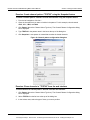
3. To create the example script, enter the name, column_and_row_labels, in the TSP Script box.
Figure 22: Enter script name
4. Enter the code below in the box below the buttons:
channel.setlabelrow("1A01", "SMU1")
channel.setlabelrow("1B01", "SMU2")
channel.setlabelrow("1C01", "GNDU")
channel.setlabelrow("1G01", "CVUH")
channel.setlabelrow("1H01", "CVUL")
channel.setlabelcolumn("1A01", "DUT1")
channel.setlabelcolumn("1B02", "DUT2")
channel.setlabelcolumn("1C03", "DUT3")
channel.open("allslots")
channel.close("SMU1+DUT3")
3-12
707B-900-01 Rev. A / August 2010
Test Equipment Depot - 800.517.8431 - 99 Washington Street Melrose, MA 02176 - TestEquipmentDepot.com
Models 707B and 708B Switching Matrix User's Manual
Section 3: Using the web interface
NOTE
Commands and parameters for Models 707B and 708B are case-sensitive. It is important to type in
the commands exactly as show to avoid any syntax and execution errors.
5. Click Save Script. The script is added to the User Scripts list.
Quick Tip
Standard edit functions, such as Copy, Cut, and Paste, work within TSB Embedded.
Figure 23: Script added to User Scripts list
6. To run the script, select the script in the User Scripts list and click Run.
7. The Instrument Output box displays any error messages and output from the script.
Script management options
Existing scripts are listed in the User Scripts box on the left side of the web interface. To delete a
script, click the name of the script and click Delete. The script is deleted from the User Scripts list and
from the nonvolatile memory of the instrument. To stop operation of a script, click Abort Script.
To export the selected script to the computer, click Export to PC. Choose the directory where you
want to save the script and click Save. Scripts are saved to a file with the extension tsp. TSP files
are native to Test Script Builder or TSB Embedded, but they can be opened and edited in any text
editor.
To import scripts from the computer, click Import to PC. Select the directory that contains the file.
You can only import files with the extension tsp.
To clear the name box and the box that contains the script, click Clear. You can type the name of a
script in the TSP Script box and click View Script to view the contents of the script.
Exercise: Use the command line to close and open channels
Use the command line interface to perform close and open operations on channels:
1. To send a single command to the instrument, you can enter it in the Console box.
2. To close channel 1B02, enter channel.close("1B02") in the Console box.
707B-900-01 Rev. A / August 2010
Test Equipment Depot - 800.517.8431 - 99 Washington Street Melrose, MA 02176 - TestEquipmentDepot.com
3-13
Section 3: Using the web interface
Models 707B and 708B Switching Matrix User's Manual
3. Click Enter to send the command.
Figure 24: Enter command in Console box
4. To open all channels, enter channel.open("allslots") in the Console box.
5. Click Enter to send the command.
6. To resend a command, click the drop-down arrow on the left side of the Console box.
Figure 25: Model 707B or 708B web interface console
More information about commands to control the instrument can be found in the Models 707B and
708B Reference Manual.
3-14
707B-900-01 Rev. A / August 2010
Test Equipment Depot - 800.517.8431 - 99 Washington Street Melrose, MA 02176 - TestEquipmentDepot.com
Section 4
Working with the Model 4200-SCS
In this section:
Introduction ................................................................ 4-1
Equipment required to run the example ..................... 4-1
Configure Model 707B or 708B for Model 4200-SCS. 4-1
Add Model 707B or 708B to Model 4200-SCS ........... 4-2
Next steps .................................................................. 4-3
Introduction
You can connect the Model 4200 Semiconductor Characterization System to a Model 707B or 708B.
This enables the Model 4200-SCS to automate measurements to multiple devices for DC, CV, and
pulsed I-V characterization.
This section describes:
•
How to configure the Model 707B or 708B for use with the Model 4200-SCS
•
How to add the Model 707B or 708B to a Model 4200-SCS
•
Where to look for more information
Equipment required to run the example
To run this test, you will need the following equipment:
•
One Model 4200-SCS instrument
•
GPIB cable to connect the Model 707B or 708B to the Model 4200
•
Model 707B or 708B and associated switch cards
Configure Model 707B or 708B for Model 4200-SCS
To use the Model 707B or 708B with the Model 4200-SCS, first configure the Model 707B or 708B to
use compatible Model 707A commands:
1. Press MENU.
2. Select DDC.
Test Equipment Depot - 800.517.8431 - 99 Washington Street Melrose, MA 02176 - TestEquipmentDepot.com
Section 4: Working with the Model 4200-SCS
Models 707B and 708B Switching Matrix User's Manual
3. Select ENABLE.
4. Select 70xA-VERSION. The instrument displays the message “Must Power Cycle for DDC
to enable."
Figure 26: Front panel DDC enable menu
DDC ENABLE
70xA-VERSION 70xB-VERSION OFF
5. Press ENTER.
6. Cycle power to the instrument.
NOTE
When DDC mode is enabled (70xA-VERSION OR 70xB-VERSION), the Model 707B or 708B sends a
different identification string in response to the “*IDN?” query. With DDC mode enabled, the response
of the 707B to “*IDN?” is:
707A03
With DDC mode disabled (OFF), the response to “*IDN?” is:
KEITHLEY INSTRUMENTS INC, MODEL 707B, <serial #>, <firmware rev>
Add Model 707B or 708B to Model 4200-SCS
To add the Model 707B or 708B to the Model 4200-SCS:
1. Connect the Model 707B or 708B to the GPIB controller on the Model 4200.
2. Ensure that the Model 707B or 708B has a GPIB address that is different than any other
instrument connected to the Model 4200-SCS and is different than the controller's address.
3. On the Model 4200, open KCON.
4. In KCON, open the Tools menu.
5. Select Add External Instrument.
6. Select Switch Matrix.
7. Select Model 707/707A Switching Matrix. Note that the instrument is added to the Configuration
Navigator. In the KCON Workspace, the Switch System Properties dialog box is displayed.
8. Enter the appropriate GPIB Address for the Model 707B or 708B.
9. Select an instrument connection scheme.
10. Select the switch cards that you have already installed in the Model 707B or 708B.
11. From the Tools menu, check the configuration by selecting Validate Configuration.
4-2
707B-900-01 Rev. A / August 2010
Test Equipment Depot - 800.517.8431 - 99 Washington Street Melrose, MA 02176 - TestEquipmentDepot.com
Models 707B and 708B Switching Matrix User's Manual
Section 4: Working with the Model 4200-SCS
12. When the Model 4200-SCS finds the Model 707B or 708B, a green check mark appears next to
“Verifying Keithley 707A Switching Matrix.” If there is an error, a red X appears next to “Verifying
Keithley 707A Switching matrix.” An error description is provided. Generally, these errors are
associated with an incorrect GPIB address.
13. From the File menu, save the current configuration by selecting Save Configuration.
You can now use the Model 707B or 708B with the Model 4200-SCS.
Next steps
See the Model 4200-SCS Reference Manual, "Appendix B: Using Switch Matrices," "Key Concepts"
section, which includes:
•
Switch matrix connection scheme settings for row-column and instrument cards
•
Configuring switch card property configurations in KCON
•
Connecting the Model 4200-SCS instrument to the Model 707B or 708B
•
Accessing and using the user module library to control the switch matrix
See "Section 15: Multi-Frequency C-V measurements" in the Model 4200-SCS Reference Manual,
which includes information on using the Model 4200-CVU card with a switch matrix.
To customize the switch user library of the Model 4200-SCS, see the Models 707B and 708B
Reference Manual, "Using Models 707A and 708A compatibility mode".
707B-900-01 Rev. A / August 2010
Test Equipment Depot - 800.517.8431 - 99 Washington Street Melrose, MA 02176 - TestEquipmentDepot.com
4-3
Test Equipment Depot - 800.517.8431 - 99 Washington Street Melrose, MA 02176 - TestEquipmentDepot.com
Section 5
Working with the Series 2600A
In this section:
About the Series 2600A examples ............................. 5-1
Equipment required to run the examples ................... 5-2
Connect the equipment .............................................. 5-2
Logical block diagram of test connections.................. 5-3
Example 1: Control with separate interfaces .............. 5-4
Example 2: Using TSP-Link to configure instruments 5-7
Example 3: Configure using TSP-Link and interactive
triggers ..................................................................... 5-12
Example 4: Using the scanning and triggering model5-17
About the Series 2600A examples
This section shows you how to use the Model 707B or 708B with a Series 2600A System
SourceMeter® instrument to perform an I-V sweep across a diode. In each example, the Model 707B
or 708B connects a diode across the output of SMUA of the Series 2600A SourceMeter Instrument
(SMU). The SMU then performs an I-V sweep across the diode.
There are four examples in this section, progressing from using direct control over the remote
communication interface to automating the sweep using the scan and trigger model.
Example 1 shows you how to control the Series 2600A and Model 707B or 708B instruments using
direct control over the remote communication interface. This example:
•
Demonstrates how to use the PC to send commands to each instrument separately and cannot be run
using TSB Embedded. It requires a separate application development environment.
•
Requires two communication identifiers, such as the GPIB address or LAN IP address. One is required
for the Model 707B or 708B and the other for the Series 2600A.
•
Does not require TSP-Link.
•
Does not use hardware triggering or the scanning and triggering model of the Model 707B or 708B.
Example 2 shows you how to use TSP-Link to configure the Series 2600A and Model 707B or 708B
instruments. This example:
•
Can be run using TSB Embedded.
•
Demonstrates how to configure the TSP-Link interface for communication between the instruments.
•
Requires unique TSP-Link node numbers for each instrument.
•
Demonstrates the benefit of using the TSP-Link interface to send commands to another instrument.
•
Does not require hardware triggering or the scanning and triggering model of the Model 707B or 708B.
Test Equipment Depot - 800.517.8431 - 99 Washington Street Melrose, MA 02176 - TestEquipmentDepot.com
Section 5: Working with the Series 2600A
Models 707B and 708B Switching Matrix User's Manual
Example 3 shows you how to use the TSP-Link interface and interactive triggering with Series 2600A
and Model 707B or 708B instruments. This example:
•
Can be run using TSB Embedded.
•
Demonstrates how to create, load, and execute a TSP script that includes functions.
•
Demonstrates how to use the functions in the script to run the test.
•
Demonstrates the benefit of using TSP scripts to run the test independently of computer control after
initiating a test to run.
•
Uses the TSP-Link interface for communication and interactive hardware triggering.
•
Does not use the scanning and triggering model of the Model 707B or 708B.
Example 4 shows you how to use the scanning and triggering model of the Model 707B or 708B with
the SourceMeter instrument. This example:
•
Can be run using TSB Embedded.
•
Demonstrates how to create, load, and execute a TSP script that includes functions, and how to use
those functions to run the test.
•
Demonstrates the benefit of using TSP scripts to run the test independently of computer control after
initiating a test to run.
•
Uses the TSP-Link interface for communication and interactive hardware triggering.
•
Demonstrates how to use the scanning and triggering model to achieve hardware synchronization
during a test.
•
Illustrates the speed advantage of preconfiguring the sequence of crosspoints used during the test.
•
Includes instructions on how to create a scan list, how to execute a foreground scan, how to configure
the trigger model to automatically wait for and assert trigger signals.
Equipment required to run the examples
To run this test, you will need the following equipment:
•
Six diodes with triaxial connections
•
One Model 707B or 708B
•
One switch matrix card (Model 7174A, 7072, or 7072-HV). You can also use the Model 7173-50 if you
convert the connection to coaxial instead of triaxial.
•
One Model 2635A SourceMeter Instrument or equivalent source measurement unit (SMU). You can use
the Models 2601A and 2611A SourceMeter instruments if an adaptation is made from the screw
terminals on the instrument to the triaxial connections on the switch card.
Connect the equipment
The communication setup and hardware changes for each of the examples and is described at the
beginning of each example. However, all of the examples use the same test equipment setup, as
shown in the following figure.
5-2
707B-900-01 Rev. A / August 2010
Test Equipment Depot - 800.517.8431 - 99 Washington Street Melrose, MA 02176 - TestEquipmentDepot.com
Models 707B and 708B Switching Matrix User's Manual
Section 5: Working with the Series 2600A
NOTE
This figure shows connections to the Model 7072 8x12 Switch Card. However, you can make similar
connections to the other switch cards listed for this example.
Figure 27: Connections to switching module
Model 2635A
Model 7072
8x12 Switch Matrix Card
Mounting
screw
Columns
1 - 12
Rows
A-H
1
A
2
Low-current
rows
B
3
C
4
Model 7078-TRX-*
Triax Cable Assembly
D
5
6
Carrying
handle
7
8
E
Setup Notes:
(1) This drawing illustrates connections to the Model 7072 8x12
Switch Matrix Card. Connections to other cards supported by the
70xB System Switch are similar.
9
F
10
G
CV
rows
11
H
12
(2) All triaxial connections for both the Sourcemeter® instrument and
the diodes are made to the center conductor (pin) of the triaxial
connector.
Mounting
screw
Logical block diagram of test connections
The following figure shows the logical block diagram of the test connections.
707B-900-01 Rev. A / August 2010
Test Equipment Depot - 800.517.8431 - 99 Washington Street Melrose, MA 02176 - TestEquipmentDepot.com
5-3
Section 5: Working with the Series 2600A
Models 707B and 708B Switching Matrix User's Manual
Figure 28: Logical block diagram of test connections
1
2
3
4
5
6
7
8
9
10
11
12
A
2635A HI
2635A LO
B
C
D
E
F
G
H
Example 1: Control with separate interfaces
Controlling Series 2600A and Model 707B or 708B instruments using separate communication
interfaces
To run this test, you create a table on the Model 707B or 708B that contains the crosspoints that are
needed to connect the SMU to each diode under test, one at a time. The SMU then performs an I-V
sweep on the diode. Data from the SMU is returned to the controlling computer after all six diodes
have been tested.
Set up communication
The communication setup is illustrated in the diagram below. GPIB is used as an example, but this
application can be run using any of the supported communication interfaces for the instruments.
Figure 29: GPIB communication setup
GPIB
Model 707B or 708B System Switch
Controller
Series 2600A
SMU
5-4
707B-900-01 Rev. A / August 2010
Test Equipment Depot - 800.517.8431 - 99 Washington Street Melrose, MA 02176 - TestEquipmentDepot.com
Models 707B and 708B Switching Matrix User's Manual
Section 5: Working with the Series 2600A
Example program code for the Model 707B or 708B
NOTE
The example code does not include programming syntax to issue commands from the host computer
over GPIB or LAN communication interfaces. It cannot be run using TSB Embedded. You are
expected to send the instrument commands by means of a separate application development
environment, such as Microsoft® Visual Studio® or National Instruments Labview™.
Send the following commands to configure the Model 707B or 708B.
Example program code for the Model 707B or 708B
Code
Notes and comments
reset
errorqueue.clear()
Reset the instrument to factory defaults.
Clear all errors.
matrixChannels = {}
Define the table that details crosspoints to
close to connect each diode to the
source-measure unit (SMU).
matrixChannels[1]
matrixChannels[2]
matrixChannels[3]
matrixChannels[4]
matrixChannels[5]
matrixChannels[6]
=
=
=
=
=
=
"1A01,1B02"
"1A03,1B04"
"1A05,1B06"
"1A07,1B08"
"1A09,1B10"
"1A11,1B12"
Add entries to the table.
Example program code for the Model 2635
Send the following commands to configure the Model 2635 System SourceMeter Instrument.
707B-900-01 Rev. A / August 2010
Test Equipment Depot - 800.517.8431 - 99 Washington Street Melrose, MA 02176 - TestEquipmentDepot.com
5-5
Section 5: Working with the Series 2600A
Models 707B and 708B Switching Matrix User's Manual
Example program code for the Model 2635 System SourceMeter Instrument
Code
Notes and comments
reset()
errorqueue.clear()
smua.nvbuffer1.clear()
Reset the instrument.
Clear all errors and reset status bits.
Clear existing data from the data buffer.
smua.source.func = smua.OUTPUT_DCAMPS
smua.source.rangei = 0.01
Set source function to current source.
Set source current range to 10 mA.
smua.measure.rangev = 6
smua.measure.nplc = 1
smua.nvbuffer1.appendmode = 1
Set voltage measurement range to 6 V.
Set integration rate.
Enable buffer append mode.
smua.trigger.source.limitv = 10
smua.trigger.source.lineari(0, 0.01, 11)
smua.trigger.source.action = smua.ENABLE
Set the voltage compliance during the sweep.
Configure linear staircase sweep.
Enable the source action during the sweep.
smua.trigger.measure.v(smua.nvbuffer1)
smua.trigger.measure.action =
smua.ENABLE
Configure sweep voltage measurements.
Enable voltage measurements.
smua.trigger.count = 11
smua.trigger.arm.count = 1
Set trigger count to number of steps in the
sweep.
Set arm count to number of sweeps to perform.
Example code to run the test
To run the test, send the following commands to the corresponding instrument.
5-6
707B-900-01 Rev. A / August 2010
Test Equipment Depot - 800.517.8431 - 99 Washington Street Melrose, MA 02176 - TestEquipmentDepot.com
Models 707B and 708B Switching Matrix User's Manual
Section 5: Working with the Series 2600A
Example program code to run the test
Model
Code
Notes and comments
2635A
smua.source.output = 1
Turn on the Model 2635A output.
707B or 708B
channel.exclusiveclose(matrixChannels[1])
Connect first diode
2635A
smua.trigger.initiate()
waitcomplete()
Initiate sweep.
Wait until sweep is complete.
707B or 708B
channel.exclusiveclose(matrixChannels[2])
Connect second diode.
2635A
smua.trigger.initiate()
waitcomplete()
Initiate sweep.
Wait until sweep is complete.
707B or 708B
channel.exclusiveclose(matrixChannels[3])
Connect third diode.
2635A
smua.trigger.initiate()
waitcomplete()
Initiate sweep.
Wait until sweep is complete.
Model 707B or
708B
channel.exclusiveclose(matrixChannels[4])
Connect fourth diode.
2635A
smua.trigger.initiate()
waitcomplete()
Initiate sweep.
Wait until sweep is complete
707B or 708B
channel.exclusiveclose(matrixChannels[5])
Connect fifth diode
2635A
smua.trigger.initiate()
waitcomplete()
Initiate sweep
Wait until sweep is complete
707B or 708B
channel.exclusiveclose(matrixChannels[6])
Connect sixth diode
2635A
smua.trigger.initiate()
waitcomplete()
smua.source.output = 0
Initiate sweep.
Wait until sweep is complete, then
turn off the output.
707B or 708B
channel.open('allslots')
Open all crosspoints
2635A
printbuffer(1,smua.nvbuffer1.n,
smua.nvbuffer1.readings)
Retrieve data from the Model 2635A.
Example 2: Using TSP-Link to configure instruments
Using TSP-Link to configure the Series 2600A and Model 707B or 708B
This example is identical to the test in example 1, except that TSP-Link is used to communicate to the
Model 2635 System SourceMeter instrument from the Model 707B or 708B.
To run this test, you create a table on the Model 707B or 708B that contains the crosspoints that are
needed to connect the SMU to each diode under test, one at a time. The SMU then performs an I-V
sweep on the diode. Data from the SMU is returned to the controlling computer after all six diodes
have been tested.
707B-900-01 Rev. A / August 2010
Test Equipment Depot - 800.517.8431 - 99 Washington Street Melrose, MA 02176 - TestEquipmentDepot.com
5-7
Section 5: Working with the Series 2600A
Models 707B and 708B Switching Matrix User's Manual
Set up communication
The communication setup is illustrated in the diagram below. GPIB is used as an example, but this
application can be run using any of the supported communication interfaces for the instruments. A
TSP-Link connection enables communication between the two instruments and commands for the
SourceMeter (on TSP-Link node 2) are sent over the TSP-Link interface.
Figure 30: GPIB and TSP-Link connections
GPIB
Model 707B or 708B System Switch
(TSP-Link Node #1)
TSP-Link
Series 2600A
SMU
(TSP-Link Node #2)
To configure the TSP-Link communication interface, each instrument must have a unique TSP-Link
node number. Configure the node number for the Model 707B or 708B to 1 and the SourceMeter
Instrument to 2.
To set the TSP-Link node number using the front panel interface of either instrument:
1. Press MENU.
2. Select TSPLink.
3.
Select NODE.
4. Use the navigation wheel
to adjust the node number.
5. Press ENTER to save the TSP-Link node number.
On the Model 707B or 708B, perform a TSP-Link reset to alert the Model 707B or 708B to the
presence of the SMU:
1. Press MENU.
2. Select TSPLink.
3. Select RESET.
Quick Tip
You can also perform a TSP-Link reset from the remote command interface by sending
tsplink.reset() to the Model 707B or 708B. This command is also included in the example
program code below for completion.
5-8
707B-900-01 Rev. A / August 2010
Test Equipment Depot - 800.517.8431 - 99 Washington Street Melrose, MA 02176 - TestEquipmentDepot.com
Models 707B and 708B Switching Matrix User's Manual
Section 5: Working with the Series 2600A
NOTE
If error 1205 is generated during the TSP-link reset, ensure that the Model 2635 System SourceMeter
instrument has a unique TSP-Link node number.
Example program code
The example code to configure the Model 707B or 708B and System SourceMeter Instrument shown
below is identical to the code used in Example 1. However, in this example, all commands are sent to
the Model 707B or 708B. This example can be run using TSB Embedded. Commands for the Model
2635 System SourceMeter have the TSP-Link node number appended to the beginning of the
command (node[2]).
In the following table, the Model 707B or 708B sends the commands in the shaded rows to the
System SourceMeter instrument through the TSP-Link interface. Commands in unshaded rows are
executed by the Model 707B or 708B.
707B-900-01 Rev. A / August 2010
Test Equipment Depot - 800.517.8431 - 99 Washington Street Melrose, MA 02176 - TestEquipmentDepot.com
5-9
Section 5: Working with the Series 2600A
Models 707B and 708B Switching Matrix User's Manual
Example program code for the Model 707B or 708B
Code
Notes and comments
tsplink.reset()
localnode.reset()
errorqueue.clear()
Reset TSP-Link.
Reset Model 707B or 708B.
Clear errors.
matrixChannels = {}
Define table that details crosspoints to close to connect
each diode to the SMU.
matrixChannels[1]
matrixChannels[2]
matrixChannels[3]
matrixChannels[4]
matrixChannels[5]
matrixChannels[6]
=
=
=
=
=
=
"1A01,
"1A03,
"1A05,
"1A07,
"1A09,
"1A11,
1B02"
1B04"
1B06"
1B08"
1B10"
1B12"
Add entries to the table.
node[2].reset()
node[2].errorqueue.clear()
node[2].smua.nvbuffer1.clear()
Reset the instrument.
Clear all errors and reset status bits.
Clear existing data from data buffer.
node[2].smua.source.func =
node[2].smua.OUTPUT_DCAMPS
node[2].smua.source.rangei = 0.01
Set source function to current source.
node[2].smua.measure.rangev = 6
node[2].smua.measure.nplc = 1
node[2].smua.nvbuffer1.appendmode = 1
Set voltage measurement range to 6 V.
Set integration rate.
Enable buffer append mode.
node[2].smua.trigger.source.limitv = 10
node[2].smua.trigger.source.lineari
(0, 0.01, 11)
node[2].smua.trigger.source.action =
node[2].smua.ENABLE
Set the voltage compliance during the sweep.
Configure linear staircase sweep.
node[2].smua.trigger.measure.v
(node[2].smua.nvbuffer1)
node[2].smua.trigger.measure.action =
node[2].smua.ENABLE
Configure sweep voltage measurements.
node[2].smua.trigger.count = 11
Set trigger count to the number of steps in the sweep.
node[2].smua.trigger.arm.count = 1
Set arm count to the number of sweeps to perform each
time the sweep is initiated.
Set source current range to 10 mA.
Enable the source action during the sweep.
Enable voltage measurements during the sweep.
Example code to run the test
To run the test, send the following commands to the Model 707B or 708B.
5-10
707B-900-01 Rev. A / August 2010
Test Equipment Depot - 800.517.8431 - 99 Washington Street Melrose, MA 02176 - TestEquipmentDepot.com
Models 707B and 708B Switching Matrix User's Manual
Section 5: Working with the Series 2600A
Example program code to run the test
Code
Notes and comments
node[2].smua.source.output = 1
Turn on the output of the Model 2635A.
channel.exclusiveclose(matrixChannels[1])
Connect first diode.
node[2].smua.trigger.initiate()
waitcomplete()
Initiate sweep.
Both instruments wait until sweep is complete.
channel.exclusiveclose(matrixChannels[2])
Connect second diode.
node[2].smua.trigger.initiate()
waitcomplete()
Initiate sweep.
Both instruments wait until sweep is complete
channel.exclusiveclose(matrixChannels[3])
Connect third diode.
node[2].smua.trigger.initiate()
waitcomplete()
Initiate sweep.
Both instruments wait until sweep is complete.
channel.exclusiveclose(matrixChannels[4])
Connect fourth diode.
node[2].smua.trigger.initiate()
waitcomplete()
Initiate sweep.
Both instruments wait until sweep is complete.
channel.exclusiveclose
(matrixChannels[5])
Connect fifth diode.
node[2].smua.trigger.initiate()
waitcomplete()
Initiate sweep.
Both instruments wait until sweep is complete.
channel.exclusiveclose(matrixChannels[6])
Connect sixth diode.
node[2].smua.trigger.initiate()
waitcomplete()
smua.source.output = 0
Initiate sweep.
Both instruments wait until the sweep is complete.
The SMU output is turned off.
channel.open("allslots")
Open all crosspoints.
To retrieve data from the System SourceMeter instrument through the TSP-Link interface, use the
printbuffer() command to print the data to the computer communication interface. An example is
shown below.
Example: Retrieve buffer data
Code
printbuffer(1, node[2].smua.nvbuffer1.n,
node[2].smua.nvbuffer1.readings)
Notes and comments
Print all readings from the SMU data buffer. Note that
"readings" is a buffer attribute.
707B-900-01 Rev. A / August 2010
Test Equipment Depot - 800.517.8431 - 99 Washington Street Melrose, MA 02176 - TestEquipmentDepot.com
5-11
Section 5: Working with the Series 2600A
Models 707B and 708B Switching Matrix User's Manual
Example 3: Configure using TSP-Link and interactive triggers
This example uses a TSP script to configure and run the test. The script includes two separate
functions for configuring the Model 707B or 708B and System SourceMeter Instrument and a third
function for running the test. Configuration for both instruments is similar to examples 1 and 2 except
that TSP-Link trigger lines are used to coordinate the actions between the two instruments.
When the test is run, the instruments assert trigger signals after completing their respective actions.
After connecting the diode, the Model 707B or 708B sends a trigger signal to the System
SourceMeter instrument. The SMU then performs a single I-V sweep on the diode and sends a trigger
signal back to the Models 707B and 708B to indicate that the test is completed. Hardware
handshaking continues in this fashion until all six diodes have been tested. Data from the SMU is
returned to the controlling computer at the end of all the tests.
Quick Tip
A TSP script is a sequence of instrument commands and programming statements. The Model 707B
or 708B can store the TSP script for later use. Using scripts allows the Model 707B or 708B to
perform simple and complex tasks with less interaction with the remote interface controller (the
controlling computer). For more information on using scripts, please see "Instrument Programming" in
the Models 707B and 708B Reference Manual.
Set up communication
In this example, in addition to the TSP-Link interface serving as a communication bus, it will also
serve as triggering bus to enable hardware handshaking between the System SourceMeter
instrument and Model 707B or 708B.
The communication setup is identical to the setup in Example 2; see Set up communication (on page
5-8).
There are three digital lines in the TSP-Link cable that may be used for triggering. This example uses
trigger lines 1 and 2. The Model 707B or 708B outputs a trigger signal on TSP-Link line 1 and waits
for a trigger signal on TSP-Link line 2 before proceeding with the next set of crosspoint closures. The
System SourceMeter instrument outputs a trigger signal on TSP-Link line 2 after completing its test
and waits for a trigger signal on TSP-Link line #1 before testing. The triggering setup is illustrated in
the figure below.
5-12
707B-900-01 Rev. A / August 2010
Test Equipment Depot - 800.517.8431 - 99 Washington Street Melrose, MA 02176 - TestEquipmentDepot.com
Models 707B and 708B Switching Matrix User's Manual
Section 5: Working with the Series 2600A
Figure 31: TSP-Link interface
Model 2635A System SourceMeter®
Instrument
Model 707B or 708B System Switch
TSP-Link® Interface
Communication lines
Trigger line #1
Close
crosspoint
Trigger line #2
Perform
I-V sweep
Trigger line #3
Note:
Trigger line #3 is not used in the example.
Example program code
In the following table, all commands are sent from the computer to the Model 707B or 708B. This
example can be run using TSB Embedded. The Model 707B or 708B sends all commands in the
shaded rows to the System SourceMeter instrument through the TSP-Link interface. Commands in
unshaded rows are executed by the Model 707B or 708B.
707B-900-01 Rev. A / August 2010
Test Equipment Depot - 800.517.8431 - 99 Washington Street Melrose, MA 02176 - TestEquipmentDepot.com
5-13
Section 5: Working with the Series 2600A
Models 707B and 708B Switching Matrix User's Manual
Example program code for the Model 707B or 708B
Code
Notes and comments
loadscript diodeTest
Create a script "diodeTest" to
contain test configuration and
execution instructions.
function configSwitch()
Create a function to configure the
Model 707B or 708B.
tsplink.reset()
localnode.reset()
errorqueue.clear()
Reset TSP-Link.
Reset Model 707B or 708B.
Clear errors.
matrixChannels = {}
Define table that details
crosspoints to close to connect
each diode to the SMU.
matrixChannels[1]
matrixChannels[2]
matrixChannels[3]
matrixChannels[4]
matrixChannels[5]
matrixChannels[6]
=
=
=
=
=
=
"1A01,
"1A03,
"1A05,
"1A07,
"1A09,
"1A11,
1B02"
1B04"
1B06"
1B08"
1B10"
1B12"
tsplink.trigger[1].mode = tsplink.TRIG_FALLING
tsplink.trigger[2].mode = tsplink.TRIG_FALLING
tsplink.trigger[1].clear()
tsplink.trigger[2].clear()
Set TSP-Link lines 1 and 2 to send
and receive falling-edge triggers .
Clear any latched triggers on
TSP-Link trigger lines 1 and 2.
return matrixChannels
end
Return the table as an output of
the function.
function configSMU()
Create a function to configure the
System SourceMeter instrument.
node[2].reset()
node[2].errorqueue.clear()
node[2].smua.nvbuffer1.clear()
Reset the instrument.
Clear all errors and reset status
bits.
Clear existing data from data
buffer.
node[2].smua.source.func =
node[2].smua.OUTPUT_DCAMPS
Set source function to current
source.
Set source current range to
10 mA.
node[2].smua.source.rangei = 0.01
node[2].smua.measure.rangev = 6
node[2].smua.measure.nplc = 1
node[2].smua.nvbuffer1.appendmode = 1
node[2].smua.trigger.source.limitv = 10
node[2].smua.trigger.source.lineari(0, 0.01, 11)
node[2].smua.trigger.source.action =
node[2].smua.ENABLE
5-14
Add entries to the table.
Set voltage measurement range to
6 V.
Set integration rate.
Enable buffer append mode.
Set voltage compliance during
sweep.
Configure linear staircase sweep.
Enable the source action during
the sweep.
707B-900-01 Rev. A / August 2010
Test Equipment Depot - 800.517.8431 - 99 Washington Street Melrose, MA 02176 - TestEquipmentDepot.com
Models 707B and 708B Switching Matrix User's Manual
Section 5: Working with the Series 2600A
node[2].smua.trigger.measure.v(node[2].smua.nvbuffe
r1)
Configure sweep voltage
measurements.
Enable voltage measurements
during the sweep.
node[2].smua.trigger.measure.action =
node[2].smua.ENABLE
node[2].smua.trigger.count = 11
node[2].smua.trigger.arm.count = 6
Set trigger count to the number of
steps in the sweep.
Set arm count to six, the total
number of sweeps that will be run
for all diodes.
node[2].tsplink.trigger[1].mode =
node[2].tsplink.TRIG_FALLING
node[2].tsplink.trigger[2].mode =
node[2].tsplink.TRIG_FALLING
Set TSP-Link trigger lines 1 and 2
to send and receive falling edge
trigger signals.
node[2].tsplink.trigger[1].clear()
node[2].tsplink.trigger[2].clear()
Clear any latched triggers on
TSP-Link trigger lines 1 and 2.
node[2].smua.trigger.arm.stimulus =
node[2].tsplink.trigger[1].EVENT_ID
Configure sweep to start when
signal received on TSP-Link line 1.
node[2].tsplink.trigger[2].stimulus =
node[2].smua.trigger.SWEEP_COMPLETE_EVENT_ID
Configure System SourceMeter to
output trigger signal on TSP-Link
line 2 when sweep is complete.
end
function runDiodeTest()
This function sequences the
crosspoint closures and triggering.
xptTable = configSwitch()
Call the function to configure the
switch storing the result in the
variable xptTable.
configSMU()
node[2].smua.source.output = 1
Call function to configure the SMU
and turn on its output.
node[2].smua.trigger.initiate()
Initiate the System SourceMeter
so that it is ready to sweep once a
trigger signal is received (the
output turns on but no power is
applied).
707B-900-01 Rev. A / August 2010
Test Equipment Depot - 800.517.8431 - 99 Washington Street Melrose, MA 02176 - TestEquipmentDepot.com
5-15
Section 5: Working with the Series 2600A
Models 707B and 708B Switching Matrix User's Manual
for i = 1, table.getn(xptTable) do
if i > 1 then
triggered = tsplink.trigger[2].wait(3)
if triggered == true then
channel.exclusiveclose(xptTable[i])
tsplink.trigger[1].assert()
else
print("Trigger not received")
end
else
channel.exclusiveclose(xptTable[i])
tsplink.trigger[1].assert()
The "for" loop iterates through the
channel list, waiting three seconds
for a trigger on TSP-Link line 2
before closing a channel. The first
channel of the list does not wait for
a trigger. After channel closure is
complete, an output trigger is
asserted on TSP-Link line 1.
end
end
After all switch and measure
actions have completed, turn off
the SMU output, open all
crosspoints, and print "done"; the
computer controller can query for
"done" to determine when the test
is complete.
waitcomplete()
node[2].smua.source.output = 0
channel.open("allslots")
print("done")
end
Ends the function "runDiodeTest."
endscript
Ends the script "diodeTest."
Example program code to run the test
The example program code stores the program in the instrument for later use. To run the program,
send the following commands to the Model 707B or 708B.
Example program code to run the test
Code
diodeTest()
runDiodeTest()
Notes and comments
Run the script to define the functions.
Execute the test by calling the function that configures the instruments
and sequences their actions.
To retrieve data from the System SourceMeter instrument through TSP-Link, use the
printbuffer() command to print the data to the computer communication interface. An example is
shown below.
Example: Retrieve buffer data
Code
printbuffer(1, node[2].smua.nvbuffer1.n,
node[2].smua.nvbuffer1.readings)
5-16
Notes and comments
Print all readings from the SMU data buffer. Note that
"readings" is a buffer attribute.
707B-900-01 Rev. A / August 2010
Test Equipment Depot - 800.517.8431 - 99 Washington Street Melrose, MA 02176 - TestEquipmentDepot.com
Models 707B and 708B Switching Matrix User's Manual
Section 5: Working with the Series 2600A
Example 4: Using the scanning and triggering model
This example demonstrates how to use the scanning and triggering model of the Model 707B or 708B
to maximize the speed of the test by preconfiguring the sequence of crosspoints used.
This example uses a TSP script to configure the instruments for testing. Once the instruments are
configured, the Model 707B or 708B internally manages all close and open actions, as well as any
triggering signals, to interface with the System SourceMeter instrument. No separate script is required
to sequence these actions.
As with the previous examples, a full I-V sweep is performed on each of the six diodes. Data from
these tests is available from the System SourceMeter instrument after all tests have been completed.
Set up communication
In this example, in addition to the TSP-Link interface serving as a communication bus, it will also
serve as triggering bus to enable hardware handshaking between the System SourceMeter
instrument and Model 707B or 708B.
The communication setup is identical to the setup in Example 2; see Set up communication (on page
5-8).
There are three digital lines in the TSP-Link cable that may be used for triggering. This example uses
trigger lines 1 and 2. The Model 707B or 708B outputs a trigger signal on TSP-Link line 1 and waits
for a trigger signal on TSP-Link line 2 before proceeding with the next set of crosspoint closures. The
System SourceMeter instrument outputs a trigger signal on TSP-Link line 2 after completing its test
and waits for a trigger signal on TSP-Link line #1 before testing. The triggering setup is illustrated in
the figure named "TSP-Link interface" in Example 3: Configure using TSP-Link and interactive
triggers (on page 5-12).
Example program code
In the following table, all commands are sent from the computer to the Model 707B or 708B. This
example can be run using TSB Embedded. The Model 707B or 708B sends all commands in the
shaded rows to the System SourceMeter instrument through the TSP-Link interface. Commands in
unshaded rows are executed by the Model 707B or 708B.
707B-900-01 Rev. A / August 2010
Test Equipment Depot - 800.517.8431 - 99 Washington Street Melrose, MA 02176 - TestEquipmentDepot.com
5-17
Section 5: Working with the Series 2600A
Models 707B and 708B Switching Matrix User's Manual
Example program code for the Model 707B or 708B
Code
Notes and comments
loadscript diodeTest
Create a script "diodeTest" to contain
test configuration and execution
instructions.
function configSwitch()
Create a function to configure the
Model 707B or 708B.
tsplink.reset()
localnode.reset()
errorqueue.clear()
Reset TSP-Link.
Reset Model 707B or 708B.
Clear errors.
matrixChannels = {}
Define table that details crosspoints to
close to connect each diode to the
SMU.
matrixChannels[1]
matrixChannels[2]
matrixChannels[3]
matrixChannels[4]
matrixChannels[5]
matrixChannels[6]
=
=
=
=
=
=
"1A01,
"1A03,
"1A05,
"1A07,
"1A09,
"1A11,
1B02"
1B04"
1B06"
1B08"
1B10"
1B12"
for i = 1, 6 do
scan.addimagestep(matrixChannels[i])
end
tsplink.trigger[1].mode = tsplink.TRIG_FALLING
tsplink.trigger[2].mode = tsplink.TRIG_FALLING
tsplink.trigger[1].clear()
tsplink.trigger[2].clear()
scan.bypass = scan.ON
scan.trigger.arm.stimulus = 0
scan.trigger.channel.stimulus =
tsplink.trigger[2].EVENT_ID
tsplink.trigger[1].stimulus =
scan.trigger.EVENT_CHANNEL_READY
scan.scancount = 1
5-18
Add entries to the table.
Use the values in the table to create a
scan list.
Set TSP-Link lines 1 and 2 to send
and receive falling-edge triggers.
Clear any latched triggers on
TSP-Link trigger lines 1 and 2.
Configure the scanning and triggering
mode of Model 707B or 708B. Bypass
needed for trigger signal to start scan.
Arm scan immediately.
Trigger channel close action with
receipt of trigger on TSP-Link line 2.
Output trigger on TSP-link line 1 after
channel close action occurs.
Loop through scan list once.
end
End of the configSwitch function.
function configSMU()
Create a function to configure the
System SourceMeter instrument.
707B-900-01 Rev. A / August 2010
Test Equipment Depot - 800.517.8431 - 99 Washington Street Melrose, MA 02176 - TestEquipmentDepot.com
Models 707B and 708B Switching Matrix User's Manual
Section 5: Working with the Series 2600A
node[2].reset()
Reset the instrument.
node[2].errorqueue.clear()
Clear all errors and reset status bits.
Clear existing data from data buffer.
node[2].smua.nvbuffer1.clear()
node[2].smua.source.func =
node[2].smua.OUTPUT_DCAMPS
Set source function to current source.
Set source current range to 10 mA.
node[2].smua.source.rangei = 0.01
node[2].smua.measure.rangev = 6
node[2].smua.measure.nplc = 1
node[2].smua.nvbuffer1.appendmode = 1
node[2].smua.trigger.source.limitv = 10
node[2].smua.trigger.source.lineari(0, 0.01, 11)
node[2].smua.trigger.source.action =
node[2].smua.ENABLE
node[2].smua.trigger.measure.v(node[2].smua.nvbuf
fer1)
Set voltage measurement range to
6V
Set integration rate.
Enable buffer append mode.
Set the voltage compliance during the
sweep.
Configure linear staircase sweep.
Enable the source action during the
sweep.
Configure sweep voltage
measurements.
Enable voltage measurements during
the sweep.
node[2].smua.trigger.measure.action =
node[2].smua.ENABLE
node[2].smua.trigger.count = 11
Set trigger count to the number of
steps in the sweep.
node[2].smua.trigger.arm.count = 6
Set arm count to six, the total number
of sweeps that will be run for all
diodes.
node[2].tsplink.trigger[1].mode =
node[2].tsplink.TRIG_FALLING
node[2].tsplink.trigger[2].mode =
node[2].tsplink.TRIG_FALLING
Set TSP-Link trigger lines 1 and 2 to
send and receive falling edge trigger
signals.
node[2].tsplink.trigger[1].clear()
node[2].tsplink.trigger[2].clear()
Clear any latched triggers on
TSP-Link trigger lines 1 and 2.
node[2].smua.trigger.arm.stimulus =
node[2].tsplink.trigger[1].EVENT_ID
Configure sweep to start when signal
received on TSP-Link line 1.
node[2].tsplink.trigger[2].stimulus =
node[2].smua.trigger.SWEEP_COMPLETE_EVENT_ID
Configure System SourceMeter to
output trigger signal on TSP-Link line
2 when sweep is complete.
end
End of the function "Config SMU."
707B-900-01 Rev. A / August 2010
Test Equipment Depot - 800.517.8431 - 99 Washington Street Melrose, MA 02176 - TestEquipmentDepot.com
5-19
Section 5: Working with the Series 2600A
Models 707B and 708B Switching Matrix User's Manual
This function sequences the
crosspoint closures and triggering.
function runDiodeTest()
configSwitch()
Call function to configure the Model
707B or 708B.
configSMU()
node[2].smua.source.output = 1
Call function that configures the
System SourceMeter instrument and
turns on its output.
Initiate the System SourceMeter so
that it is ready to sweep once a trigger
signal is received. Note that the output
turns on but no power is applied.
Initiate the System Switch to start a
foreground scan. Waits until Model
2635A finishes all measurements.
Remote operation pauses until all six
tests are complete. For other options
on running a scan, see the box "Using
background scans for longer scans."
node[2].smua.trigger.initiate()
scan.execute()
waitcomplete()
Turn off the SMU output.
Open all crosspoints.
node[2].smua.source.output = 0
channel.open("allslots")
end
Ends the runDiodeTest function.
endscript
Ends the diodeTest script.
Example program code to run the test
The example program code stores the program in the instrument for later use. To run the program,
send the following commands to the Model 707B or 708B.
Example program code to run the test
Code
diodeTest()
runDiodeTest()
Notes and comments
Run the script to define the functions.
Execute the test by calling the function that configures the instruments
and sequences their actions.
To retrieve data from the System SourceMeter instrument through TSP-Link, use the
printbuffer() command to print the data to the computer communication interface. An example is
shown below.
Example: Retrieve buffer data
Code
printbuffer(1, node[2].smua.nvbuffer1.n,
node[2].smua.nvbuffer1.readings)
5-20
Notes and comments
Print all readings from the SMU data buffer. Note that
"readings" is a buffer attribute.
707B-900-01 Rev. A / August 2010
Test Equipment Depot - 800.517.8431 - 99 Washington Street Melrose, MA 02176 - TestEquipmentDepot.com
Models 707B and 708B Switching Matrix User's Manual
Section 5: Working with the Series 2600A
Using background scans for longer scan lists
Example 4 illustrates use of the scanning and triggering model to create a foreground scan.
While running a foreground scan, you must wait for the scan to complete or you must abort the scan
before you can query the instrument state or any reading buffers. For a scan with a few channels or
crosspoints in the scan list, this might not be a problem. However, when there are many channels in
the scan list, or when scans are run over long time periods, it can be useful to determine instrument
state. In these situations, you can run a background scan. A background scan allows you to query
settings during a scan.
To change Example 4 from a foreground scan to a background scan, you need to change one
command in the "runDiodeTest" function. Change scan.execute() to scan.background(). You
can then use the scan.state() command to query the status of the scan, including the number of
steps in the scan, the number of steps performed, and the number of entire scans performed.
The following table shows a revised example of the runDiodeTest function in Example 4.
function runDiodeTest()
configSwitch()
configSMU()
node[2].smua.source.output = 1
node[2].smua.trigger.initiate()
scan.background()
delay(2)
scanState, scanCount, stepCount = scan.state()
print(scanState, " ", scanCount, " ", stepCount, "
")
while scanState ~=6 do
delay(1)
end
node[2].smua.source.output = 0
channel.open("allslots")
end
This function sequences
the crosspoint closures
and triggering.
Call function to configure
the Model 707B or 708B.
Call function that
configures the System
SourceMeter instrument
and turns on its output.
Initiate the System
SourceMeter so that it is
ready to sweep once a
trigger signal is received.
Note that the output turns
on but no power is applied.
Initiate the System Switch
to start a background scan.
Delay 2 seconds to allow
the scan to start.
Use variables to hold the
scan state response.
Print the response to scan
state, which you can use to
determine when the scan
is complete.
Query the scan state every
second to determine when
the scan completes.
When the scan is complete
(scan state = 6), exit
the loop.
Turn off the SMU output.
Open all crosspoints.
Ends the runDiodeTest
function.
707B-900-01 Rev. A / August 2010
Test Equipment Depot - 800.517.8431 - 99 Washington Street Melrose, MA 02176 - TestEquipmentDepot.com
5-21
Test Equipment Depot - 800.517.8431 - 99 Washington Street Melrose, MA 02176 - TestEquipmentDepot.com
Section 6
Working with the Series 2400
In this section:
About the Series 2400 examples ............................... 6-1
Equipment required to run the examples ................... 6-1
Connect the equipment .............................................. 6-1
Logical block diagram of test connections.................. 6-2
Example 1: Individual commands for switch-measure 6-3
Example 2: Digital I/O triggering for switch-measure
synchronization .......................................................... 6-5
About the Series 2400 examples
This section provides examples that demonstrate the basic interaction of the Model 707B or 708B
with a Model 2400 SourceMeter Instrument. One of the examples also shows how to use digital I/O
triggering to synchronize source and measure actions between the Model 707B or 708B and the
SourceMeter instrument.
The concepts in these examples can be applied when using the Model 707B or 708B with other
SCPI-based instruments. TSB Embedded cannot be used to program the Model 2400 SourceMeter
Instrument; it cannot be used for these examples.
Equipment required to run the examples
To run this test, you will need the following equipment:
•
Six diodes with triaxial connections
•
One Model 707B or 708B
•
One switch matrix card (Model 7174A, 7072, or 7072-HV). You can also use the Model 7173-50 if you
convert the connection to coaxial instead of triaxial
•
One Model 2400 SourceMeter instrument or equivalent source measurement unit (SMU)
•
Example 2 only: One Model 2600-TLINK trigger link to digital I/O cable assembly
•
Two Model 237-BAN-3A banana jack to triaxial cable assemblies
Connect the equipment
To run the test, make the connections as shown in the figure below. Note that all triax connections for
the SourceMeter Instrument and the diodes are made to the center conductor (pin) of the triaxial
connector.
Test Equipment Depot - 800.517.8431 - 99 Washington Street Melrose, MA 02176 - TestEquipmentDepot.com
Section 6: Working with the Series 2400
Models 707B and 708B Switching Matrix User's Manual
NOTE
This drawing shows connections to the Model 7072 8x12 Switch Card. However, you can make
similar connections to the other switch cards listed for this example.
Model 2600-TLINK
TriggerLink to digital I/O
cable assembly
Connect to the digital I/O
connector on the rear panel of the
Model 70xB system switch
Model 2400
Model 7072
8x12 Switch Matrix Card
Mounting
screw
Columns
1 - 12
Rows
A-H
1
A
Low-current
rows
2
B
3
C
4
Model 237-BAN-3A
Triax to banana cable assembly
D
5
6
Carrying
handle
7
8
E
Setup Notes:
(1) This drawing illustrates connections to the Model 7072 8x12
Switch Matrix Card. Connections to other cards supported by the
70xB System Switch are similar.
9
F
10
CV
rows
G
11
H
12
(2) All triaxial connections for both the Sourcemeter® instrument and
the diodes are made to the center conductor (pin) of the triaxial
connector.
Mounting
screw
Logical block diagram of test connections
The following figure shows the logical block diagram of the test connections.
6-2
707B-900-01 Rev. A / August 2010
Test Equipment Depot - 800.517.8431 - 99 Washington Street Melrose, MA 02176 - TestEquipmentDepot.com
Models 707B and 708B Switching Matrix User's Manual
Section 6: Working with the Series 2400
Figure 32: Test system block diagram
Example 1: Individual commands for switch-measure
In this example, individual commands are sent to the Model 707B or 708B and SourceMeter
Instrument to perform switch closure and measure actions.
Example program code for the Model 2400
NOTE
TSB and TSB Embedded cannot be used to control the Model 2400 SourceMeter instrument. You are
expected to send commands to the Model 2400 using a separate application development
environment, such as Microsoft® Visual Studio® or National Instruments LabVIEW™.
Send the following commands to configure the Model 2400 SourceMeter Instrument.
707B-900-01 Rev. A / August 2010
Test Equipment Depot - 800.517.8431 - 99 Washington Street Melrose, MA 02176 - TestEquipmentDepot.com
6-3
Section 6: Working with the Series 2400
Models 707B and 708B Switching Matrix User's Manual
Example program code for the Model 2400 SourceMeter Instrument
Code
Notes and comments
*RST
*CLS
:FORM:ELEM VOLT, CURR
Reset the instrument.
Clear all errors and reset status bits.
Format return data string to return current and voltage values.
:SOUR:FUNC CURR"
:SOUR:CURR:MODE SWE
:SOUR:CURR:STAR 0
:SOUR:CURR:STOP 10E-3
:SOUR:CURR:STEP 1e-3
:SOUR:SWE:SPAC LIN
Configure current source to perform a linear sweep from 0 to
10 mA in 1 mA steps.
:SENS:VOLT:PROT 10
:SENS:FUNC 'VOLT'
:SENS:VOLT:RANG 5
:SENS:VOLT:NPLC 1
Configure voltage limit.
Configure SMU to measure voltage.
Set a fixed voltage range of 5 V.
Set integration rate to 1 PLC.
:ARM:COUN 1
:TRIG:COUN 11
Complete each sweep once.
Number of steps in sweep = 11.
Example program code for the Model 707B or 708B
Send the following commands to configure the Model 707B or 708B.
Example program code for the Model 707B or 708B
Code
reset
errorqueue.clear()
Notes and comments
Reset the instrument to factory defaults.
Clear all errors.
To run the test, send the following commands to the corresponding instrument.
NOTE
After each :READ? query to the Model 2400, you must retrieve the instrument's response. If you do
not retrieve the response, the Model 2400 generates an error.
6-4
707B-900-01 Rev. A / August 2010
Test Equipment Depot - 800.517.8431 - 99 Washington Street Melrose, MA 02176 - TestEquipmentDepot.com
Models 707B and 708B Switching Matrix User's Manual
Section 6: Working with the Series 2400
Example program code to run the test
Model
Code
Notes and comments
2400
:OUTP:STAT ON
Turn on the output of the SourceMeter
instrument.
707B or 708B
channel.exclusiveclose("1A01,1B02")
Connect first diode.
2400
:READ?
Initiate sweep and return data.
707B or 708B
channel.exclusiveclose("1A03,1B04")
Connect second diode.
2400
:READ?
Initiate sweep and return data.
707B or 708B
channel.exclusiveclose("1A05,1B06")
Connect third diode.
2400
:READ?
Initiate sweep and return data.
707B or 708B
channel.exclusiveclose("1A07,1B08")
Connect fourth diode.
2400
:READ?
Initiate sweep and return data.
707B or 708B
channel.exclusiveclose("1A09,1B10")
Connect fifth diode.
2400
:READ?
Initiate sweep and return data.
707B or 708B
channel.exclusiveclose("1A11,1B12")
Connect sixth diode.
2400
:READ?
Initiate sweep and return data.
2400
:OUTP:STAT OFF
Turn off the output of the SourceMeter
instrument.
707B or 708B
channel.open("allslots")
Open all crosspoints.
Example 2: Digital I/O triggering for switch-measure
synchronization
In this example, you will configure both the Model 707B or 708B and the SourceMeter instrument to
wait for and send digital trigger signals after each performs the requested switch closure or measure
action.
Example program code for the Model 2400
NOTE
TSB and TSB Embedded cannot be used to control the Model 2400 SourceMeter. You are expected
to send commands to the Model 2400 using a separate application development environment, such
as Microsoft Visual Studio or National Instruments' Labview.
Send the following commands to configure the Model 2400 SourceMeter Instrument.
707B-900-01 Rev. A / August 2010
Test Equipment Depot - 800.517.8431 - 99 Washington Street Melrose, MA 02176 - TestEquipmentDepot.com
6-5
Section 6: Working with the Series 2400
Models 707B and 708B Switching Matrix User's Manual
Example program code for the Model 2400 SourceMeter Instrument
Code
Notes and comments
*RST
*CLS
:FORM:ELEM VOLT, CURR
Reset the instrument.
Clear all errors and reset status bits.
Format return data string to return current and voltage values.
:SOUR:FUNC CURR
:SOUR:CURR:MODE SWE
:SOUR:CURR:STAR 0
:SOUR:CURR:STOP 10E-3
:SOUR:CURR:STEP 1e-3
:SOUR:SWE:SPAC LIN
Configure current source to perform a linear sweep from 0 to
10 mA in 1 mA steps.
:SENS:VOLT:PROT 10
:SENS:FUNC 'VOLT'
:SENS:VOLT:RANG 5
:SENS:VOLT:NPLC 1
Configure voltage limit.
Configure the SMU to measure voltage.
Set a fixed voltage range of 5 V.
Set integration rate to 1 PLC.
:ARM:DIR ACC
:ARM:SOUR TLINK
:ARM:ILIN 1
:ARM:OLIN 2
:ARM:OUTP TEXIT
:TRIG:DIR ACC
:TRIG:SOUR IMM
:TRIG:COUN 11
:ARM:COUN 6
Configure the SMU to trigger entire sweep on receipt of
hardware trigger on the TriggerLink connector.
Configure the SMU to receive a trigger on line 1 and to
generate a trigger on line 2.
:TRAC:POIN 66
:TRAC:FEED SENS
:TRAC:FEED:CONT NEXT
Configure the nonvolatile data buffer of the SMU to store all
66 sets of readings generated for sweeps across all diodes.
Configure the counts of the trigger model so that the 11-point
sweep is performed six times (once for each diode).
Example program code for the Model 707B or 708B
The following code loads a script on the 70xB that contains two functions that:
6-6
•
Set up the table of crosspoints to close
•
Execute the test
707B-900-01 Rev. A / August 2010
Test Equipment Depot - 800.517.8431 - 99 Washington Street Melrose, MA 02176 - TestEquipmentDepot.com
Models 707B and 708B Switching Matrix User's Manual
Section 6: Working with the Series 2400
Example program code for the Model 707B or 708B
Code
Notes and comments
loadscript forScan
This script creates two functions on the Model
707B or 708B to configure and run the test.
This script should be stored in the Model 707B
or 708B.
Remember that loadscript and endscript
commands are not necessary if this script is
created in the instrument using TSB or TSB
Embedded.
function setup70xChanList()
Create a function that sets up the Model 707B
or 708B and the list of channels to be used in
the test.
Reset the instrument and clear errors.
reset()
errorqueue.clear()
chanTable = {}
chanTable[1] =
chanTable[2] =
chanTable[3] =
chanTable[4] =
chanTable[5] =
chanTable[6] =
"1A01,1B02"
"1A03,1B05"
"1A05,1B06"
"1A07,1B08"
"1A09,1B10"
"1A11,1B12"
digio.trigger[1].mode = digio.TRIG_FALLING
digio.trigger[2].mode = digio.TRIG_FALLING
digio.trigger[1].clear()
digio.trigger[2].clear()
Define and populate a table that holds the
crosspoints to be used to connect the SMU to
the diodes under test (also see notes below this
example).
Configure the digital I/O trigger lines to respond
to and generate falling edge triggers.
Clear any latched triggers.
Return the table as an output of the function
return chanTable
end
707B-900-01 Rev. A / August 2010
Test Equipment Depot - 800.517.8431 - 99 Washington Street Melrose, MA 02176 - TestEquipmentDepot.com
6-7
Section 6: Working with the Series 2400
Models 707B and 708B Switching Matrix User's Manual
function run70xForScan(cTable)
for i = 1, table.getn(cTable) do
if i > 1 then
triggered = digio.trigger[2].wait(3)
if triggered == true then
channel.exclusiveclose(cTable[i])
waitcomplete()
digio.trigger[1].assert()
else
print("Trigger not received")
end
else
channel.exclusiveclose(cTable[i])
waitcomplete()
digio.trigger[1].assert()
end
end
print("done")
end
This function sequences the crosspoint
closures and hardware triggering. A table of
crosspoints to close must be input to this
function.
The for loop iterates through the channel list
and waits for a trigger on a digital I/O line to
occur before closing a channel.
The first channel of the list does not wait for a
trigger.
After channel closure is complete, an output
trigger is asserted on digital I/O line.
endscript
forScan()
Run the script to generate the functions.
crossptTable = setup70xChanList()
Call the function that sets up the Model 707B or
708B and store the output of the function in the
variable crossptTable.
Alternate method for creating a list of crosspoints
The following code creates a list of crosspoints that can be used in a test. This code replaces
chanTable in the example code above.
x = 1
--The following nested for loop creates channel list for the scan.
compiled in the table "jscTable"
for i = 1,11,2 do
j = i + 1
chan1 = channel.createspecifier(1,1,i)
chan2 = channel.createspecifier(1,2,j)
chanTable[x] = chan1 .. "," .. chan2
--Crosspoints are printed to show output of example
print(chanTable[x])
x = x+1
end
--This list is
Output:
1A01,1B02
1A03,1B05
1A05,1B06
1A07,1B08
1A09,1B10
1A11,1B12
6-8
707B-900-01 Rev. A / August 2010
Test Equipment Depot - 800.517.8431 - 99 Washington Street Melrose, MA 02176 - TestEquipmentDepot.com
Models 707B and 708B Switching Matrix User's Manual
Section 6: Working with the Series 2400
Overview of running the test
The Model 707B or 708B closes the crosspoints necessary to connect the SourceMeter to each diode
under test one-at-a-time. The SourceMeter then performs an I-V sweep on each diode. This process
continues until all six diodes are tested.
Example code to run the test
To run the test, send the following commands to the corresponding instrument.
Example program code to run the test
Model
Code
Notes and comments
2400
:OUTP ON
Turn on the output of the SourceMeter
Instrument.
2400
:INIT
Initiate the sweep. After processing this
command, the Model 2400 waits for a trigger
from the Model 707B or 708B.
707B or 708B
run70xForScan(crossptTable)
Call the function that executes the sequence
of crosspoints and generates hardware trigger
signals to trigger sweeps on the SMU.
2400
:TRAC:DATA?
After the test is complete, send this command
to retrieve the data from the Model 2400.
Retrieve the data from the Model 2400 after
sending :TRAC:DATA?.
707B-900-01 Rev. A / August 2010
Test Equipment Depot - 800.517.8431 - 99 Washington Street Melrose, MA 02176 - TestEquipmentDepot.com
6-9
Test Equipment Depot - 800.517.8431 - 99 Washington Street Melrose, MA 02176 - TestEquipmentDepot.com
Section 7
Troubleshooting FAQs
In this section:
About this section....................................................... 7-1
Need different line frequency or voltage..................... 7-1
Model 4200-SCS does not recognize switch matrix ... 7-1
"A" model software does not run on "B" models......... 7-3
Matrix Ready and External Trigger lines .................... 7-3
Switch matrix does not recognize my card ................. 7-3
Instrument's internal web page is not accessible ....... 7-4
Error when I try to close a channel............................. 7-5
Switch relays will not close......................................... 7-5
Save the present state of the instrument.................... 7-5
LabVIEW driver for the Model 707B or 708B ............. 7-6
About this section
The intent of this section is to troubleshoot the most common problems encountered with the Models
707B and 708B. For additional troubleshooting information, please see the "Troubleshooting" section
in the Models 707B and 708B Reference Manual.
Need different line frequency or voltage
I need to use 707B or 708B at a different line frequency or voltage. What do I need to do?
The Model 707B or 708B only supports a line frequency of 50/60 Hz. The line frequency is
automatically sensed and no user action is needed.
Model 4200-SCS does not recognize switch matrix
The Model 4200-SCS does not recognize the Model 707B or 708B. What do I do?
To work with the Model 4200-SCS, you must have DDC compatibility mode enabled and must
communicate through the GPIB.
Test Equipment Depot - 800.517.8431 - 99 Washington Street Melrose, MA 02176 - TestEquipmentDepot.com
Section 7: Troubleshooting FAQs
Models 707B and 708B Switching Matrix User's Manual
You can select one of two options when enabling Model 707A or 708A DDC compatibility mode:
•
70xA-VERSION: This option most closely matches Model 707A or 708A operation. Use this
version if you are transferring applications directly from a Model 707A or 708A with few changes.
•
70xB-VERSION: This options provides enhanced operation, including error checking and more
robust settling time operation. Use this version if you are updating existing applications.
To enable Model 707A or 708A DDC compatibility mode:
1. From the front panel, select MENU.
2. Select DDC.
3. Select ENABLE.
4. Select the version.
5. Press ENTER.
6. Cycle instrument power.
To enable GPIB communications:
1. From the front panel, select MENU.
2. Select GPIB.
3. Select ENABLE.
4. Select ON.
5. Cycle power to the instrument.
If DDC compatibility mode is selected and GPIB is enabled, also verify that:
7-2
•
The GPIB cable is connected to the instrument.
•
The instrument has a unique GPIB address.
707B-900-01 Rev. A / August 2010
Test Equipment Depot - 800.517.8431 - 99 Washington Street Melrose, MA 02176 - TestEquipmentDepot.com
Models 707B and 708B Switching Matrix User's Manual
Section 7: Troubleshooting FAQs
"A" model software does not run on "B" models
Software that I used with my Model 707A or 708A does not run on the Model 707B or 708B.
What do I do?
Verify that DDC compatibility mode is enabled.
You can select one of two options when enabling Model 707A or 708A DDC compatibility mode:
•
70xA-VERSION: This option most closely matches Model 707A or 708A operation. Use this
version if you are transferring applications directly from a Model 707A or 708A with few changes.
•
70xB-VERSION: This options provides enhanced operation, including error checking and more
robust settling time operation. Use this version if you are updating existing applications.
To enable Model 707A or 708A DDC compatibility mode:
1. From the front panel, select MENU.
2. Select DDC.
3. Select ENABLE.
4. Select the version.
5. Press ENTER.
Cycle instrument power.
Review "Using Model 707A and 708A compatibility mode" in the Models 707B and 708B Reference
Manual for additional information. Also see "Migrating from Models 707A and 708A."
Matrix Ready and External Trigger lines
Does this model have Matrix Ready and External Trigger lines?
Yes, these signals appear on the digital I/O connector. For information on the digital I/O capabilities,
refer to "Controlling digital I/O lines" in the Model 707B or 708B Reference Manual. If you wish to use
a Model 707B or 708B in an existing Model 707A or 708A application, please refer to "Using Model
707A or 708A compatibility mode" in the Model 707B or 708B Reference Manual.
Switch matrix does not recognize my card
The Model 707B or 708B does not recognize my switch card. What do I do?
707B-900-01 Rev. A / August 2010
Test Equipment Depot - 800.517.8431 - 99 Washington Street Melrose, MA 02176 - TestEquipmentDepot.com
7-3
Section 7: Troubleshooting FAQs
Models 707B and 708B Switching Matrix User's Manual
Card is not correctly seated in the slot
Check the seating of the card:
1. Remove power from the instrument.
2. Pull the card out of the slot.
3. Carefully guide the card inside the rails while re-installing.
4. Make sure the outer shield is not inserted into the card rails.
5. Make sure that no other portions of the card catch on any part of the instrument frame while
installing.
6. Make sure the card is fully seated before restarting the instrument.
Edge connector is dirty
If the card was stored outside of the instrument, it is possible that the edge connector has gotten dirty.
1. Check the edge connector. The gold edge connector fingers should have a bright surface when
properly cleaned.
2. If necessary, clean the edge connector.
3. Re-install the card.
Confirm that the card is supported in the Model 707B or 708B
See the Models 707B and 708B specifications.
Instrument's internal web page is not accessible
I cannot access the instrument's internal web page. How do I fix this?
Ensure that the instrument has a valid and unique IP address assigned.
7-4
•
To view the IP address of the Models 707B and 708B, press MENU. Select LAN > STATUS >
IP-ADDRESS. If a valid IP address is displayed, the instrument configuration is correct. If 0.0.0.0
is displayed, the IP address is not valid.
•
If you are using the automatic configuration method over a corporate network, contact your
network administrator for assistance.
•
If you are using the automatic configuration method and you have a one-to-one connection
between the instrument and the computer, verify that the computer is set to receive an IP address
automatically. When the computer and the Model 707B or 708B synchronize, the green LED
status light on the front panel of the instrument lights.
•
If you are using the manual configuration method over a corporate network, verify that you have
entered the IP address, gateway and subnet mask provided by your network administrator.
•
If you are using the manual configuration method and a one-to-one connection with the computer,
verify that the subnet mask agrees with the computer's settings.
•
If the above suggestion do not work, see Models 707B and 708B Reference Manual,
"Communication interfaces."
707B-900-01 Rev. A / August 2010
Test Equipment Depot - 800.517.8431 - 99 Washington Street Melrose, MA 02176 - TestEquipmentDepot.com
Models 707B and 708B Switching Matrix User's Manual
Section 7: Troubleshooting FAQs
Error when I try to close a channel
The instrument generates an error when I try to close a channel. What do I do?
If the instrument generates "Error 1115: Parameter error no forbidden channels accepted," make sure
that the channel specifier is valid. For more information on channel specifiers, see Channel identifiers
(on page 2-7).
If the specifier is correct, the channel's forbidden attribute may be set to true. To close the specified
channel, the forbidden attribute must be set to false.
To set the forbidden attribute to false using the front panel:
1. Press CONFIG then CHAN.
2. Select FORBID.
3. Select NO.
To set the forbidden attribute to false using the web interface:
1. On the Cards page, right-click the channel.
2. Clear the Forbidden box.
3. Click OK.
To set the forbidden attribute to false using remote commands:
Use the command:
channel.setforbidden()
Switch relays will not close
Why are the switch relays not closing?
Verify that the system power is sufficient to close the switch relays.
Check the front panel or script output for error that might have been returned from the operation.
Save the present state of the instrument
How do I save the present state of the instrument?
Use the Create Config Script option (or the command createconfigscript). See the Models 707B and
708B Reference Manual, "Save the present configuration."
707B-900-01 Rev. A / August 2010
Test Equipment Depot - 800.517.8431 - 99 Washington Street Melrose, MA 02176 - TestEquipmentDepot.com
7-5
Section 7: Troubleshooting FAQs
Models 707B and 708B Switching Matrix User's Manual
LabVIEW driver for the Model 707B or 708B
Where do I find the LabVIEW driver for the Model 707B or 708B?
The latest Labview driver is always available from the Keithley Instrument's support website
(http://www.keithley.com/support).
7-6
707B-900-01 Rev. A / August 2010
Test Equipment Depot - 800.517.8431 - 99 Washington Street Melrose, MA 02176 - TestEquipmentDepot.com
Section 8
Next steps
This manual has prepared you to start using your new Model 707B or 708B for your real-world
applications. For more detailed information about the Model 707B or 708B, refer to the Keithley
Instruments Models 707B and 708B Reference Manual, part number 707B-901-01.
If you are migrating from a Keithley Model 707A or 708A, and wish to use the native commands for
the Model 707B or 708B, please refer to the "Migrating from Models 707A and 708A" topic in the
"Features and Functions" section of the Model 707B or 708B Reference Manual. If you would like to
use existing software that ran with the Model 707A or 708A without modification, please refer to
"Using Model 707A or 708A Compatibility Mode" in the Model 707B or 708B Reference Manual.
Test Equipment Depot - 800.517.8431 - 99 Washington Street Melrose, MA 02176 - TestEquipmentDepot.com
Test Equipment Depot - 800.517.8431 - 99 Washington Street Melrose, MA 02176 - TestEquipmentDepot.com
Index
2
documentation • 1-2
2400 • 6-1
F
2600 • 5-1
front panel
4
display • 2-4, 2-5, 2-9
4200 • 4-1
interface • 2-1
7
introduction • 2-1
707B-708B Quick Start Guide • 1-2
keys • 2-3, 2-4
A
Model 707B front panel • 2-2
Model 708B front panel • 2-2
applications • 1-1
H
C
CD_-ROM • 1-2
hot switching • 1-1
I
channel
designations • 2-6
I/O layer • 1-2
patterns • 2-11
IVI drivers • 1-2
channel patterns • 2-11
J
configuration
J2SE Runtime Environment • 1-2
CONFIG key • 2-4
crosspoint • 2-9
K
keys
DISPLAY • 2-4
D
L
Display
DISPLAY key • 2-4
LabVIEW drivers • 1-2
Model 707B front panel • 2-2
M
Model 708B front panel • 2-2
matrix card notation • 2-7
Test Equipment Depot - 800.517.8431 - 99 Washington Street Melrose, MA 02176 - TestEquipmentDepot.com
Index
Models 707B and 708B Switching Matrix User's Manual
N
navigation wheel • 2-3
P
POWER switch • 2-3
precautions • 1-1
S
safety precautions • 1-1
T
Test Script Builder • 1-2
Index-2
707B-900-01 Rev. A / August 2010
Test Equipment Depot - 800.517.8431 - 99 Washington Street Melrose, MA 02176 - TestEquipmentDepot.com
Warranty
Keithley Instruments, Inc. warrants this product to be free from defects in material and workmanship for
a period of one (1) year from date of shipment.
Keithley Instruments, Inc. warrants the following items for 90 days from the date of shipment: probes,
cables, software, rechargeable batteries, diskettes, and documentation.
During the warranty period, Keithley Instruments will, at its option, either repair or replace any product
that proves to be defective.
To exercise this warranty, write or call your local Keithley Instruments representative, or contact
Keithley Instruments headquarters in Cleveland, Ohio. You will be given prompt assistance and return
instructions. Send the product, transportation prepaid, to the indicated service facility. Repairs will be
made and the product returned, transportation prepaid. Repaired or replaced products are warranted
for the balance of the original warranty period, or at least 90 days.
Limitation of Warranty
This warranty does not apply to defects resulting from product modification without Keithley
Instruments’ express written consent, or misuse of any product or part. This warranty also does not
apply to fuses, software, non-rechargeable batteries, damage from battery leakage, or problems arising
from normal wear or failure to follow instructions.
THIS WARRANTY IS IN LIEU OF ALL OTHER WARRANTIES, EXPRESSED OR IMPLIED,
INCLUDING ANY IMPLIED WARRANTY OF MERCHANTABILITY OR FITNESS FOR A PARTICULAR
USE. THE REMEDIES PROVIDED HEREIN ARE BUYER’S SOLE AND EXCLUSIVE REMEDIES.
NEITHER KEITHLEY INSTRUMENTS, INC. NOR ANY OF ITS EMPLOYEES SHALL BE LIABLE FOR
ANY DIRECT, INDIRECT, SPECIAL, INCIDENTAL, OR CONSEQUENTIAL DAMAGES ARISING OUT
OF THE USE OF ITS INSTRUMENTS AND SOFTWARE, EVEN IF KEITHLEY INSTRUMENTS, INC.
HAS BEEN ADVISED IN ADVANCE OF THE POSSIBILITY OF SUCH DAMAGES. SUCH EXCLUDED
DAMAGES SHALL INCLUDE, BUT ARE NOT LIMITED TO: COST OF REMOVAL AND
INSTALLATION, LOSSES SUSTAINED AS THE RESULT OF INJURY TO ANY PERSON, OR
DAMAGE TO PROPERTY.
A GREATER MEASURE OF CONFIDENCE
Keithley Instruments, Inc.
Corporate Headquarters • 28775 Aurora Road • Cleveland, Ohio 44139
440-248-0400 • Fax: 440-248-6168 • 1-888-KEITHLEY (1-888-534-8453) • www.keithley.com
11/07
Test Equipment Depot - 800.517.8431 - 99 Washington Street Melrose, MA 02176 - TestEquipmentDepot.com
Specifications are subject to change without notice.
All Keithley trademarks and trade names are the property of Keithley Instruments, Inc.
All other trademarks and trade names are the property of their respective companies.
A
G R E A T E R
M E A S U R E
O F
C O N F I D E N C E
Keithley Instruments, Inc.
Corporate Headquarters • 28775 Aurora Road • Cleveland, Ohio 44139 • 440-248-0400 • Fax: 440-248-6168 • 1-888-KEITHLEY • www.keithley.com
12/06
Test Equipment Depot - 800.517.8431 - 99 Washington Street Melrose, MA 02176 - TestEquipmentDepot.com