1
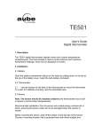
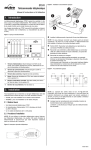
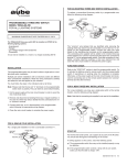
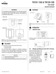
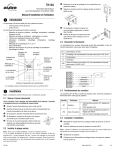
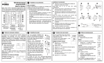
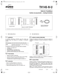
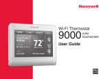
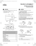
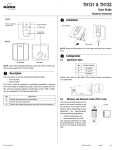
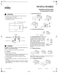
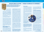
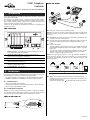
CT241 Telephone
Controller
) L J X UH Пфл д Ю Ьз ϫ Д й о пЬз з Ьпд к й
I n stall ati on I n stru c tion s and U ser M an u al
1 . Introduction
The CT241 telephone controller is designed to remotely control up to
four independent loads.
For example, you could connect a sprinkler system, a water heater,
etc. Another example would be to connect an output to the thermostat’s phone interface (which requires a dry contact) to switch from
Comfort mode to Vacation mode and vice versa.
Loads can be activated or deactivated remotely (by telephone) or
manually (on-site).
) L J X UH Л нк Я р Ю пϫ К са нсд а т
n
Mount the CT241 near a telephone outlet.
NOTE: If you plan to connect a load having more that 30 volts on the
auxiliary outputs, the CT241 must be installed inside a certified electrical box.
1
Power Indicator. Indicates the CT241 is powered on. To turn
it off, unplug the power transformer.
2
Communication Indicator. Indicates the CT241 has
answered and is awaiting a command.
3
Ring Indicator. This indicator flashes when the phone rings.
4
Reset. This button can be used to reset the CT241 to its
default values. See section 3.2.
5
Manual Output Activation Button. Can be used to manually
activate or deactivate a relay.
6
Terminal Board. See section 2.
o
OPTIONAL. Connect your phone (or answering machine) to the
PHONE connector of the CT241.
p
Connect one end of the telephone cable to the LINE connector of
the CT241 and the other end to the telephone outlet in your
home.
q
Connect the loads.
The four outputs of the CT241 allow you, for example, to activate
or deactivate the lighting system, the sprinkler system, the water
heater, etc.
You can also connect a thermostat’s telephone interface (which
requires a dry contact) to automatically switch from Comfort
mode to Vacation mode and vice versa.
NOTE: The capacity per output is 10 A @ 240 VAC. However, to
avoid electrical shocks, the direct connection of a load exceeding
30 VAC is not permitted unless the CT241 is installed inside a certified electrical box.
2. Installation
Any device connected to a telephone line must conform to the country's standards. The CT241 telephone controller meets:
• FCC68 standards for installation on the North American network.
• FDTBR21 standards for installation on the European network.
2.1 Included Parts
r
When all connections have been made, connect the power
transformer to the 9 V outlet of the CT241 and the other end to
the wall electrical outlet.
The power indicator light
is ON when the circuit is powered.
• One CT241 telephone controller)
• One power transformer 120 V (North America) or 250 V (Europe)
• One 5 m (16 foot) telephone cable
2.2 Installation Procedure
NOTE: If you are using an answering machine, position the answering machine switch to ON before installing the CT241. Make sure that
your answering machine answers after a minimum of 4 rings.
) L J X UH Ќй о та нд й в ϫ И ЬЮ г д й а ϫ О тд пЮ г
400-241-001-A
3.2 Reset Operation
3. Operation
NOTE: The CT241 will automatically hang up if no key is pressed
during the 30 seconds following the CT241 answering a call.
Insert a pointed object (e.g. paper clip) in the hole located under the
Reset light. The light will flash 3 times to indicate that the CT241 has
been reset:
• number of rings: 4
Default values: access code (1234), number of rings (4)
• access code: 1234
B E G I N A S E S S I O N ( wi t h o u t a n s we r i n g m a c h i n e )
• relays’ status: open
4. Technical Specifications
Dial your phone number
Wait for the number of rings...
Power supply: 9 VAC / 60 Hz (50 Hz Europe)
CT241 answers
Outputs: Four SPST with the following capacity:
• 5 A / 30 VAC inductive / Power Factor: 0.4
B E G I N A S E S S I O N ( wi t h a n a n s we ri n g m a c h i n e )
• 10 A / 30 VAC resistive (if installed in a certified electrical box)
• 10 A / 240 VAC resistive (if installed in a certified electrical box)
Dial your phone number
• 1/2 HP / 120 VAC motor (if installed in a certified electrical box)
Let it ring once and hang up
• 1 HP / 240 VAC motor (if installed in a certified electrical box)
Wait 10 seconds...
Protection: Class II
Access code (default): 1234
Dial your phone number again within the next 30 seconds
Number of rings (default): 4 rings
CT241 answers (1st ring)
Memory protection: In case of power failure, access code and output status are protected.
Phone certification standard:
E N TE R YO U R AC C E S S C O D E
• FDTBR21: European telephone network
Enter your 4-digit access code
(default: 1234)
Accepted
Error
• FCC68: North American telephone network
Approvals:
• c UL us (North America)
• CE (Europe)
Dimensions (H W D): 2.7 x 5.4 x 1.2 in. (69 x 137 x 31 mm)
O U TP U T S TATU S /M O D I F Y S TATU S
Press the output’s corresponding
number
for status
Press
Deactivated
(open)
Activated
(closed)
to change its status
M O D I F Y TH E AC C E S S C O D E
5. Warranty
AUBE TECHNOLOGIES INC. THREE (3) YEAR LIMITED WARRANTY
This product is guaranteed against workmanship defects for a threeyear period following the initial date of purchase. During this period,
AUBE Technologies Inc. will repair or replace, at our option and without charge, any defective product which has been used under normal
conditions.
The warranty does not cover delivery costs and does not apply to
products poorly installed or randomly damaged following installation.
Press
Enter your new 4-digit access code
Enter the access code again
Accepted
Error
M O D I F Y TH E N U M B E R O F RI N G S
This warranty cancels and replaces any other manufacturer's
express or implied warranty as well as any other company commitment. AUBE Technologies Inc. cannot be held liable for related or
random damages following the installation of this product.
The defective product as well as the purchase invoice must be
returned to the place of purchase or mailed, prepaid and insured, to
the nearest shipping address.
S K R Q H R Q O \
Press
Enter the number of rings after
which the CT241 will answer
(between 1 and 9)
x the number of
selected rings
705 Montrichard
10 Ampère Street
Saint-Jean-sur-Richelieu
95500 Gonesse
Quebec, Canada J2X 5K8
France
Tel.: 1 (450) 358-4600
33 (0) 1 34 07 99 00
Toll Free: 1-800-831-AUBE
EN D SESS I O N
Press
Fax: 1 (450) 358-4650
33 (0) 1 34 07 99 19
[email protected]
[email protected]
to end the session
3.1 Manual Output Activation Buttons
You can switch a relay status by pressing the corresponding input’s
button directly on the CT241.
For more information on our products, visit us
at: www.aubetech.com
This function is not accessible while the CT241 is answering a telephone call.
29/10/2003
400-241-001-A