1
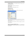
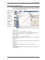
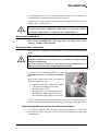
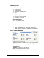
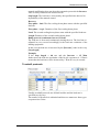
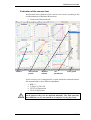
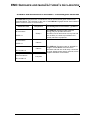
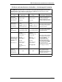
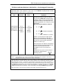
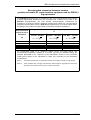
ES
Ergospirometry
Supported devices
PRE-201
Ergospirometer
Piston Ltd.
1033 Budapest, Szőlőkert u. 4/b
Rev.: ES-EN-04.10
Date modified: 31/04/2014
T ABLE OF CONTENT
Introduction ..........................................................................................................4
Devices ...............................................................................................................4
Technical overview ............................................................................................4
Installation.............................................................................................................6
PRE-201 Ergospirometer installation ...............................................................6
PRE-201 Ergospirometer patient circuit assemble ..........................................7
Ergospirometer placement.................................................................................9
Gas cylinder connection to the Ergospirometer .............................................10
User interface ..................................................................................................... 11
Settings .............................................................................................................11
Icons..................................................................................................................13
User interface - Ergospirometry......................................................................14
Calibration ......................................................................................................... 16
Flow meter calibration .....................................................................................16
Ergospirometer calibration ..............................................................................16
Measurements.................................................................................................... 18
Available examinations ...................................................................................18
Zero setting .......................................................................................................20
Preparations ......................................................................................................21
Interaction of the patient and medical devices ...............................................22
Evaluation of the cardiopulmonary test..........................................................24
Measurement modes ......................................................................................... 25
Ergospirometry.................................................................................................25
REE – Resting metabolic test..........................................................................38
Maintenance ....................................................................................................... 40
Device maintenance.........................................................................................40
Flow meter maintenance..................................................................................40
Ergospirometer maintenance...........................................................................41
Single-use parts ................................................................................................41
Reusable accessories........................................................................................41
Refill of the gas cylinders................................................................................42
Troubleshooting................................................................................................. 44
Possible problems ............................................................................................44
Technical data.................................................................................................... 45
Warranty ...........................................................................................................45
Limited liability................................................................................................45
Safety instructions............................................................................................45
Informing values ..............................................................................................46
Electrical data ...................................................................................................46
Mechanical data ...............................................................................................47
Guaranteed values ............................................................................................47
List of accessories ............................................................................................48
EMC Guidance and manufacturer’s declaration ........................................ 49
Introduction
INTRODUCTION
Devices
PRE-201 Ergospirometer
Measurement operating modes
• Forced inspiration and expiration
• Static vital capacity
• Maximum voluntary ventilation
• Resting ECG
• Ergometry
• Ergospirometry + EKG
• Resting Energy Expenditure (REE)
Design
• Flow meter: PPF-18 PinkFlow, symmetric Pitot tube
• Fast O2 and CO2 gas analyzer
• USB computer connection
• PC cart, 2 twin-monitor design
• Isolation transformer (optional)
• Calibration gas mixture: 16% O2 and 5% CO2
• Loading devices (optional): bicycle ergometer or treadmill
Technical overview
Lung diagnostic device family main parts description:
Flow meter
PPF-18 PinkFlow, symmetric Pitot tube flow meter, which provides
pressure difference in proportion with the flow speed.
A differentiate pressure sensor converts the pressure difference to electric
signal.
Patient circuit
The patient circuit provides the connection between the patient and the
equipment it consists of the following units:
•
•
PinkFlow flow meter
Facial mask and headgear
Gas analyzer
The patient’s exhaled has mixture must be sampled and analyzed to determine oxygen consumption and CO2 production.
Elements of the gas calibration line
• High pressure gas cylinder with the calibration gas mixture
ES-4
Introduction
•
•
•
Pressure regulator
Main valve
Safety vale with pressure limitation
Elements of the gas analysis:
• Gas sampling capillary
• PermaPure moisture exchange capillary to provide normalized humidity for the gas analyzers
• Gas sampling pump
• O2 and CO2 sensors
Oxygen sensor
• Chemical cell ultra fast oxygen sensor
• Paramagnetic (non-depleting) oxygen sensor - optional
Carbon dioxide sensor
• NDIR (Non Dispersive Infra Red) fast gas analyzer
Environment status measurement module PRE-201
BTPS correction requires the measurement of the following environmental data:
•
•
•
Environment temperature
Environment relative humidity
Atmospheric pressure
Power supply PRE-201
Medical design switching power supply, which enables operating the device from any mains voltage:
•
•
Mains voltage: 90~264 VAC
Mains frequency: 50~60 Hz
ES-5
Installation
INSTALLATION
PRE-201 Ergospirometer installation
№
1
2
3
4
5
6
7
8
9
10
11
12
13
14
Colour
Yellow
Blue
White
Green
Black
White
White
White
Red
Description
Gas sampling port
Flow meter
Flow meter
LED indicating the data transfer
Outlet of the calibration gas
Intake port of the ambient air
Mains socket
Quick coupler of calibration gas
Exhaust output of calibration gas
Exhaust output of gas sample
USB port of the Ergospirometer
Intake port of the CO2 absorber
Connection
Patient circuit yellow connector
Patient circuit blue connector
Patient circuit white connector
Quick coupler of gas sampling line
Never block!
Mains cable
High pressure hose of gas cylinder
Never block!
Never block!
USB cable to the PC
Red connector of the CO2 absorber
container
Oxygen sensor holder
CO2 absorber container
ES-6
Installation
Connect the power and data cables and the pneumatic connectors of the
patient circuit to the device according to the different connector types and
colour codes!
PRE-201 Ergospirometer patient circuit assemble
Push the device into the mounting frame
Front panel pneumatic connectors must be
located at the bottom
The device should overhang on both sides
equally
Fasten the device using a 3 mm hex key
ES-7
Installation
Connect the flow meter docker to a clean PinkFlow flow meter.
Push the metal release button to remove the
PinkFlow flow meter from the docker.
Button the white adapter ring up the facial mask
Button the headgear buckle up the facial mask
Connect facial mask to the headgear
Push the smaller diameter side of the PinkFlow
flow meter into the white adapter ring
ES-8
Installation
Ergospirometer placement
There are numerous criteria of the ergospirometer placement:
Environmental requirements:
• The equipment can be used only in a well ventilated laboratory.
If the laboratory has no natural ventilation for example there is no
any open able window the equipment can be used only where an air
exchanger installed and it guarantees open air quality of the internal
air.
O2 concentration: 20.93%
CO2 maximal concentration: 400 ppm (STPD)
• Avoid one meter proximity of any heat or cold radiating objects,
like heating, cooling, window etc.
• Provide stable temperature in the laboratory avoid any fast change
of the temperature.
Safety requirements
All conditions of the resuscitation have to be provided both human and
material ones:
•
•
•
Cardiologist and professional assistant
Defibrillator
Treatment bed in one meter proximity
Conformity feeling of the patient
• The patient has to be far from the outlet of the air-conditioning
avoiding any air drafts since the patient’s body overheats because
of the exercise and could catch a cold easily.
• Locker and shower
• Relax room
ES-9
Installation
Gas cylinder connection to the Ergospirometer
Place the gas cylinder to the PC cart and
fasten it with the belt
Regularly change the sealing ring of the gas cylinder
Connect the pressure regulator to the gas cylinder
Plug the high pressure hose to the pneumatic connector of the gas cylinder
Fasten the high pressure hose using the fitting nut
Open the main valve of the gas cylinder and set
the secondary pressure to 1 bar
Caution!
As the gas calibration is completed always close the main valve of the
gas cylinder
ES-10
User interface
USER INTERFACE
Settings
Ergospirometer
Select the Ergospirometer group in the Setup/Options/Devices menu
Bicycle ergometer
Selection of the bicycle ergometer type if any connected
Treadmill
Selection of the treadmill type if any connected
Blood Pressure monitor
Available options:
•
•
•
Manual BP measurement
Ergometer type – if the loading device has a built-in blood pressure
meter
Selection of any other standalone blood pressure meter if any connected
Fitness interpretation
Fitness interpretation evaluation is based on the maximal oxygen consumption. There are two algorithms to select:
•
•
American Heart Association, 1972
Cooper Institute for Aerobics Research, 1997
BMR prediction
Basal Metabolic Rate.
There are two algorithms for calculation of reference value of the reseting metabolic rate:
•
•
Mifflin - St Jeor Equation, 1990
Harris - Benedict Equation, 1919
O2 concentration
Oxygen concentration specified in the certificate of the gas refilling
company
CO2 concentration
Carbon dioxide concentration specified in the certificate of the gas refilling company
Use filter for VO2 and VCO2Use filter for VO2 and VCO2
Enabling the averaging filters for VO2 and VCO2 calculations.
It is advisable to enable these filter during Steady state and Mixing
chamber measurements.
FVC loop on main screen
The median value of breathing can be monitored on the FVC panel. This
graph can be moved into the main window to substitute the spirogram.
ES-11
User interface
Parameter columns
The number of columns of the displayed parameters during the measurement can be specified.
Log time interval
Time interval of the registration into the log file
Mixing Chamber
Select this option if a Mixing chamber is in use
Bicycle Port setup...
Treadmill Port setup...
BP monitor Port setup...
Settings of the communication ports of different connected devices
Select the appropriate PC port where the loading equipment is connected
All the other settings should be set according to the specification of the
loading equipment.
Some settings will be automatically overridden according to the selected
loading equipment.
Bicycle Ergometer and treadmill protocols
Editing and modifying protocols are possible in the Ergospirometry
measuring window. The detailed description can be found in the Ergospirometry chapter.
ES-12
User interface
Icons
Ergospirometry
Settings
Protocol editor
Predicted values and results
Actual test
Breath median
Diary
Test interpretation, Wasserman graphs
Templates – Enter new item
Templates – Edit items
Templates – Store edited item
Templates – Delete selected item
Templates – Abandon modifications
ES-13
User interface
User interface - Ergospirometry
The following image shows the general design of the measurement
screen. The individual measurement windows may different from each
other but the main controls are identical.
Device selector
Zero setting
Menu
Navigator
Patient data
BTPS data
Complex curves
Spirogram
Timer
Parameters
Control
Device selector
Select the device to be used from the drop down list.
This is necessary if, for example, you own a Plethysmograph and a Spirometer, and would like to perform IVC measurement.
Zero setting
Runs manual Zero setting of the selected device
Without manual Zero setting the system automatically sets zero before all
measurements
Menu
The program’s general main menu, which contains the grouped basic
functions.
Navigator
Control buttons which organise the basic phases of daily routine.
Patient data
Contains the most important measurement data for the patient selected
from the database.
ES-14
User interface
BTPS data
Usually our ergospirometer is equipped with the ambient module which
measures the ambient temperature, humidity and pressure. These ambient
data are shown in BTPS fields.
If there is no ambient module connected you may enter the ambient data
manually
Overview histrogram
Graphical interpretation of the most iprotant parameters like: VO2,
VCO2, VE, Load, Heart rate, Blodd pressure, Saturation
Spirogram
Volume-time graph which monitors the breathing of the patient
Timer
May show the duration of the total test or the duration of the individual
load steps or countdowns the time
Control
These control buttons organise basic phases of daily routine as follws:
•
•
•
•
•
Start monitoring [F3]
Start measurement, beginning of the protocol [F4]
Cooling down phase
End of measurement [F5]
Store and print
ES-15
Calibration
CALIBRATION
After turning the device on and entering the BTPS data, calibration is
recommended for maximum measurement accuracy.
Calibration is recommended when starting a new shift, after flow sensor
disinfections or replacement.
IMPORTANT
If work environment conditions (temperature, air pressure, humidity) change significantly, re-calibration is recommended!
Flow meter calibration
Please make the calibration of the flow meter according to the “Spirometry” volume of this manual.
Ergospirometer calibration
Ergospirometer calibration is performed in the Spirometry/Calibration
menu.
IMPORTANT
Before calibration, the room has to be ventilated to reduce carbon
dioxide concentration!
Never breathe directly onto the device during calibration! Exhaled carbon dioxide will corrupt calibration results.
In case of several connected devices, select
Ergospirometer from the [Device selection]
list.
Prior to the calibration of the gas analyzers
make the following steps:
•
•
•
Open the main valve of the gas cylinder
Check the secondary pressure the
nominal value is 1 bar
Disconnect the gas sampling line from
the PinkFlow docker and connect it to
the Calibration gas output on the device
The gas sampling line has a quick action connector. For release the grey
button has to be pushed and for connection it is enough to push till clicks
Determining ambient carbon dioxide concentration
To measure ambient carbon dioxide concentration, select the Setup tab
and click the button [Measure CO2 ppm]. The measurement is performed
automatically.
ES-16
Calibration
Calibration of gas analyzers
The calibration of the gas analyzers is done automatically in the background during the zeroing of the flow channel.
Possible error messages
Calibration Error 1: Gas plug not connected!
In this case the connections of gas sampling line has to be checked.
Calibration Error 2: Calibration constant out of range!
Calibration Error 3: Oxygen sensor used up!
If the calibration is not accepted by the system repeat the whole procedure. If the error message appears again contact your local dealer.
Calibration Error 4: Room's air used up. Ventilate it as well as
possible!
Thoroughly ventilate the laboratory and repeat the whole calibration procedure.
ES-17
Measurements
MEASUREMENTS
Available examinations
The ergospirometer system provides the following basic lung function
tests:
•
•
•
Forced exhalation and inhalation
Static vital capacity
Hyperventilation
For detailed description please refer to the “Spirometry” volume of this
manual.
Ergospirometry
Cardiopulmonary exercise testing provides a global assessment of the integrative exercise responses involving the pulmonary and cardiovascular
system.
Detailed information may be found in the Measurement modes chapter.
Safety precautions
• The Ergospirometer can be used only by a trained and authorized
personnel
• A cardiologist has to supervise the whole exercise test procedure
• Prior to the exercise test always get know the detailed anamnesis of
the patient
• The personal and the material conditions of the resuscitations has to
be provided
In this operating mode the device measures the following parameters:
V
Actual inspiration volume
VT
Tidal volume during quiet breathing
VE
Total volume of the breathing during one minute
Volume
Tidal Volume
Minute ventilation
Load
Actual load setting of the bike ergometer
Load
Calculated load of the treadmill based on the oxygen consumption
RPM
Actual pedal revolution of the bike ergometer
BPsys, BPdia
Last values of the blood pressure
HR
Actual heart rate
Pedal revolutions
Blood pressure
Heart rate
ES-18
Measurements
HRR
Residual pulse
Difference of the maximal predicted heart rate based on the age and the
actual heart rate
HR%
Percentage of the heart rate
Percentage of the actual heart rate to the maximal predicted heart rate
based on the age
SpO2
Oxygen saturation of the blood
pO2
Momentary oxygen concentration
Saturation
Momentary O2 concentration
pCO2
Momentary CO2 concentration
Momentary carbon dioxide concentration
VO2
Momentary oxygen consumption, ml/m
Momentary O2 consumption
VCO2
Momentary CO2 production
Momentary carbon dioxide production, ml/m
PETO2
O2 concentration at the end of expiration
Oxygen concentration at the end of expiration
PETCO2
CO2 concentration at the end of expiration
Carbon dioxide concentration at the end of expiration
VE/VO2
Minute ventilation / O2 consumption
Ratio of the minute ventilation and the momentary oxygen consumption
VE/VCO2
Minute ventilation / CO2 production
Ratio of the minute ventilation and the momentary carbon dioxide production
VO2max
Maximal O2 consumption
Maximal oxygen consumption during the whole test
VCO2max
Maximal CO2 production
Maximal carbon dioxide production during the whole test
VO2/HR
Oxygen delivery by one heart beat
Oxygen/pulse
BPsys×HR
Product of systolic blood pressure and heart rate
Product of systolic blood pressure and heart rate
BR
Breath rate, breath / minute
Breath rate
RER
Respiratory Exchange Ratio
Ration of the CO2 production and O2 consumption during exercise
RQ
Respiratory Quotient
Ration of the CO2 production and O2 consumption during resting
VO2/kg
Ratio of momentary O2 consumption and body weight
Momentary O2 consumption / body weight, ml/m/kg
VCO2/kg
Ratio of momentary CO2 production and body weight
Momentary CO2 production / body weight, ml/m/kg
ES-19
Measurements
Work
Carried out work
Total carried out work during the whole exercise, kCal
MET
Metabolic Equivalent
Energy request of the physical activity. Base unit is the resting energy request of the person being tested. It is a calculated value based on the
VO2.
METc
Calculated Metabolic Equivalent
Energy request of the physical activity. Base unit is the resting energy request of the person being tested. It is a calculated value based on the
body weight and load.
Speed
Speed of the treadmill
If the loading device is a treadmill the speed of the treadmill.
If the loading device is an ergometer bike this parameter is calculated
from the oxygen consumption.
Grade
Elevation angle of the treadmill
If the loading device is a treadmill this parameter is the elevation angle of
the treadmill
REE
Resting Energy Expenditure
Resting energy expenditure in kCal / day.
This parameter is calculated from the O2 consumption and CO2 production.
Zero setting
For exact volume measurement the zero setting of flow meter channel
must be performed immediately before the measurement.
In case of Ergospirometer pneumatic valves detach the flow meter from
the pressure transducer, so zero setting occurs automatically in the background. Patient may continue breathing thru the flow meter.
Zero setting process
The program automatically starts the zero setting process immediately
before each measurement.
The system evaluates the data measured during the zero setting process,
and displays an error message and repeats the zero setting process if a
zero error is encountered.
Manual zero setting
You can reset the currently selected device anytime with the [Zero] button next to the [Device selection] list in the program header.
Notice
Zero setting is automatically performed before calibration.
ES-20
Measurements
Preparations
Device
Patient circuit
To prevent cross contamination a new disposable bacterial and viral filter
must be connected before each patient measurement.
Patient
Recommended body position
• Sitting on a chair
• Straight back
• Level head
• Tight clothing or jewels must not prevent free breathing
Directions
Prior to the tests inform the patient about the goal and way of the measurements.
For detailed description please refer to the “Spirometry” volume of this
manual.
Ergospirometry preparations
The cardio-pulmonary exercise test fully differs from the usual pulmonary function tests. It requests not only co-operation but mental and
physical abilities from the patient as well.
In order to reach the best results the patient has to be aware of the special
aspects of the exercise test in advance.
•
•
•
•
•
•
•
•
•
The exercise test physically strenuous
The exercise test has certain level of risk
Sport dress and shoes are advisable
The patient has to avoid eating before the exercise test by a few
hours
The patient has to avoid eating heavy and fatty meal before the exercise test by a few days
The patient has to avoid any heavy physical activity before the exercise test by a few days
The patient has to avoid smoking before the exercise test by at least
8 hours
Prior the exercise test a full anamnesis has to be recorded including
regular medical treatment, medicines applied especially the cardio
pulmonary aspects
The total duration of a complex exercise test including the preparation, dressing and evaluation is about one and half an hour
Resting metabolic test preparations
The relaxed metabolic test is for analyzing long duration processes therefore the patient has to be aware of the special aspects of the test well before.
ES-21
Measurements
• The patient has to avoid any heavy physical activity before the exercise test by a 48 hours
• The patient has to avoid eating and drinking before the exercise test
by a 4 hours, of course water drinking is allowed
• The patient has to have a loose and comfortable dress which provide comfortable temperature feeling
• The patient lays down and relaxes for 20 – 30minutes
• The total duration of the test is about one hour
If any of the above listed criteria is not fulfilled there is no sense to
make the exercise test
Interaction of the patient and medical devices
The proper usage of the consumable parts is necessary to reach the most
correct measurements.
Nose clip
Apply nose clip during all pulmonary function tests expect for the tests
done in facial mask in order to avoid false breathing thru the nostrils.
Mouthpieces
The mouthpiece provides the proper connection between the patient and
the device.
MPA-30 – Simple mouthpiece
Elliptic mouthpiece is for the basic pulmonary function tests
PMP-30 – Mouthpiece with bite-on grip
For the more demanding pulmonary function tests where the proper sealing is even more important like body plethysmograph or diffusion capacity test
PBF-100-G-M Bacterial and viral filer with elliptic patient side for the
basic pulmonary function tests
Facial masks
Applying facial masks makes possible
the oral and nasal breathing simultaneously. It provides more comfort and
requests less co-operation.
Facial masks are used mostly for
ergospirometry and for rhinomanometry.
•
•
Select the best fitting size for the
patient the full and proper sealing
has to be reached
Assemble the adapter ring and the
headgear
ES-22
Measurements
•
•
•
•
•
•
Place the facial mask to the patient’s face as show non the picture
Adjust the length of the belts of the headgear
Fasten the headgear with the Velcro tapes
Never push the facial mask too strong against the patient’s face
To check the proper sealing the patient has to block the orifice of
the mask with hand and has to make ex- and inspiration efforts. No
leakage is allowed at all!
If necessary select an other size of the facial masks
If the patient is not fully shaved some leakage may occur.
In this case the facial hair has to be shaved.
Blood pressure meter
A lot of different blood pressure meter can be integrated into the ergospirometer system. Always follow the regulations of the user’s manual of
the given blood pressure meter.
Take care that the built-in microphone of the
handcuff has to be in the position over the
Arteria Brachialis!
ECG
A lot of different ECG can be integrated into
the ergospirometer system. Always follow
the regulations of the user’s manual of the
given ECG device.
Bicycle ergometer
The body position may influence the maximal working capacity of the
patient. Further more the height of the saddle determines which the muscles groups will be used.
In the case of healthy patient
The ideal height of the saddle is when the patient with a stretched leg
may reach the pedals with the heel. The patient has to push the pedals
with the middle of the sole pads.
Elderly and patient moving with difficultness
Adjust the height of the saddle to reach the most comfortable and the
most sense of security for the patient.
Athlete
Athletes are mostly coming for the exercise tests to reach their limits so
the usual position is important for them.
Athletes may adjust the bicycle ergometer themselves the height and position of the saddle and the hand bar.
Right position of the foot
The ideal position of the feet is when the middle of the sole pads are on
the pedals.
ES-23
Measurements
However in the case of elderly and patient pushing the pedals with the
full sole is allowed.
Treadmill
Treadmill can be applied for all ambulatory patients but there are a number of safety precautions. Read carefully the user’s manual of the treadmill integrated into the system.
•
•
•
•
•
•
Never allow to use treadmill in a dress which may have loose part
like robe belt or too long trousers because these loose part can be
cached by the rollers!
Never touch the moving parts of the treadmill like rollers or the
height adjusting mechanism!
Never stand on the belt barefoot!
Use always training shoes!
Use always the safety belt which stops the treadmill immediately as
the patient is not able to keep the speed!
Never try to block or override the safety system of the treadmill!
Evaluation of the cardiopulmonary test
During ergospirometry only one test can be performed in contrary with
the basic pulmonary function tests when 8 tests can be performed simultaneously.
Evaluation of the cardiopulmonary test is described in the next chapter.
ES-24
Measurement modes
MEASUREMENT MODES
Ergospirometry
WARNING!
The whole ergometer test has to be supervised by a cardiologist
The detailed anamnesis has to be reordered prior to ergospirometer
test
The ergospirometer test can be performed if all the conditions of the
resuscitation are provided
Goal of the test
Cardiopulmonary exercise testing provides a global assessment of the integrative exercise responses involving the pulmonary and cardiovascular
system.
Ergospirometry is increasingly being used in a wide spectrum of clinical
applications for the evaluation of undiagnosed exercise intolerance and
exercise-related symptoms
HR, BP, SpO2 Main window
panel
Manual
trol
con- Spirogram
Parameter
table
ES-25
Measurement modes
The ergospirometer test is a rather complex measurement consequently it
requests two monitors. According to the conventions the left monitor is
for the ECG and right monitor is for the control and for the monitoring
all vital parameters.
Since different models of ECG devices can be integrated into our ergospirometer system this chapter describes the right monitor in majority.
HR, BP, SpO2 panel
The main cardiologic parameters are displayed in this panel during the
test
Main window
The main pulmonary and metabolic parameters are displayed during the
test: VO2, VCO2, VE
Manual control
The load rate of the bicycle ergometer or the speed and angle of the
treadmill can be modified at any time during the whole test
In the case of bicycle ergometer the automatic protocol is not aborted by
the manual modification only the actual load rate is increased by the
Increase value.
In the case of treadmill the automatic protocol is not modified by the
manual modification the next load steps equals to value preset in the protocol.
Spirogram
The breathing is monitored in this window the tidal volume, frequency
and the median of breathing can be observed.
Parameter table
The values of the main vital parameters are shown during the test.
Load equipment
Press the [Protocol] tab and in the [Ergometer type] section select the
load equipment to use:
•
•
•
Bicycle ergometer
Treadmill
Tidal test
The panel of protocol settings is automatically changes according to the
selected load equipment.
The detailed description of the Resting Metabolic Test can be found in
the Tidal test az REE – Resting metabolic test chapter (38. page).
ES-26
Measurement modes
Handling templates
Configurations and settings of the exercise tests can be stored in templates in the following groups:
•
•
•
•
Bicycle protocols
Treadmill protocols
Measurements of blood pressure
Limits
Creating a new template
Press the „New template” button
•
•
Give a name to the new template
Enter values in to the fields
Editing existing template
Press the „Edit template” button
Delete a template
Press the ’Delete template” button
Store
After definition of a new template or modification of an existing template:
• Push the „Store modifications” button to store modifications
• Push the „Abandon modifications” button to cancel modifications
Bicycle ergometer protocols
The loading protocols are increasing the load rate from the basic value by
a given step in certain time intervals. Practically the protocol is a
Load(Time) function. Afterwards the loading is followed by the cooling
down phases.
Load configuration
Initial value: The starting load rate of the test
Increase: Increase of the load between two steps
Manual increase: Step of the manual modification. During the manual
control of the load this value will be added to the actual load rate. The
ES-27
Measurement modes
manual modification does not abort the automatic protocols the Increase
value is always added to the actual load rate.
Step length: The load rate is increased by the specified time interval independently of the manual control
Recovery
First phase - load: The first cooling down phase starts with the specified
load rate
First phase - length: Duration of the first cooling down phase
Load: The second cooling down phase starts with the specified load rate
Length: Duration of the second cooling down phase
Ramp protocol (continuous increase of load)
The load rate is increased continuously during the test. The load rate readjusted in every second accordingly to the load rate resolution of the
loading equipment.
In this case the load rate is increased by the [Increase] value in the every
[Step length].
Example:
If the Step length = 60 sec and the Increase = 15 Watt
further more the load rate resolution of the bicycle ergometer is 1 Watt it
means that the load rate will be increased by 1 Watt in every 4 seconds.
Treadmill protocols
Usually treadmill protocols are defined in tables and the load rate is
specified step by step.
The number of protocols is unlimited and there are numerous factory preset protocols to select.
ES-28
Measurement modes
Factory preset protocols
• Bruce
• Bruce Mod
• Blake
• Blake Mod
• Naughton
• Cornell
• ACIP
• Ellestad I. and II.
Manual control
Manual increase of speed: The speed can be increased or decreased by
the specified step.
Manual increase of grade: The slope can be increased by the specified
step.
The system may override the actual settings according to the resolution
of the actual treadmill. For example an 0.1% increase can be rounded to
the smallest accepted value as 0.5% or 1%.
Manual modification does not influence the automatic protocol the next
load step will be set according to the preset values.
Setting of particular steps
Time: Duration of one step in seconds
Speed: Speed in kilometre per hour
Grade: Slope of the treadmill in percent
(For example 5% slope means 5 meters difference of level in 100 meters)
Blood pressure measurement
Individual blood pressure measuring profile can be defined for each loading equipment and for each loading protocol.
For example if the system is equipped with a bicycle ergometer and with
a treadmill as well further more a ramp protocol is used for the bicycle
ergometer and the Bruce protocol is used for the treadmill.
While using the bicycle ergometer the blood pressure will be measured
by the built-in blood pressure meter of the bicycle automatically in every
2 minutes.
While using the treadmill a warning signal for manual blood pressure
measurement will be generated in the 3. minute of the each step of the
protocol.
ES-29
Measurement modes
Manual BP measurement: The blood pressure is measured manually the
system does not control any automatic blood pressure meter. A warning
signal is generated when the blood pressure measurement is necessary.
Blood Pressure measurement is actual
Measuring period
• Independent interval: The blood pressure measurements are done
in predefined intervals calculated from the beginning of the test. It
is independent of the actually running protocol.
• Relative to the current step: The blood pressure measurement starts
in a predefined time interval calculated from the beginning of the
actual load rate step.
Limitations
The time interval defined blood pressure measurement can be used at the
following conditions:
•
•
•
This feature is not available for the ramp protocols because there
are no definitive start points of the different load rates. In this case
the [Independent interval] option has to be selected.
The duration of the load step has to be longer then specified delay
time
The cycle time of a automatic blood pressure measurement has to
be taken into consideration (30÷60 sec) when editing a load protocol and a blood pressure measurement profile
Ignore failed measurements
If a blood pressure measurement is unsuccessful only a warning message
appears.
Limits
During the exercise test some vital parameters may reach critical limits
which could be risky for the patient. These limits are partly published by
the international recommendations and partly they are determined individually for each patient.
Obviously these limits are sharply different for a healthy person or for an
ill patient (transplanted or with a pacemaker) or for a professional athlete.
If monitoring of a certain parameter is not necessary enter 0 value and
monitoring of that parameter will be suspended.
ES-30
Measurement modes
It is impossible to suspend the monitoring of maximal heart rate. If the
filed value is empty the maximal heart rate is calculated from the well
known equation:
Maximal heart rate = 220 - Age
Contraindications
According to the ATS/ACCP Statement on Cardiopulmonary Exercise
Testing (March 1, 2002) making an exercise test is severely contraindicated upon the following circumstances:
Absolute contraindications
• Acute myocardial infarction (3–5 days)
• Unstable angina
• Uncontrolled arrhythmias causing symptoms or hemodynamic
compromise)
• Syncope
• Active endocarditis
• Acute myocarditis or pericarditis
• Symptomatic severe aortic stenosis
• Uncontrolled heart failure
• Acute pulmonary embolus or pulmonary infarction
• Thrombosis of lower extremities
• Suspected dissecting aneurysm
• Uncontrolled asthma
• Pulmonary edema
• Room air desaturation at rest < 85%*
• Respiratory failure
• Acute noncardiopulmonary disorder that may affect exercise performance or be aggravated by exercise (i.e. infection, renal failure,
thyrotoxicosis)
• Mental impairment leading to inability to cooperate
Relative contraindications
• Left main coronary stenosis or its equivalent
• Moderate stenotic valvular heart disease
• Severe untreated arterial hypertension at rest (>200 mm Hg systolic, >120 mm Hg diastolic)
• Tachyarrhythmias or bradyarrhythmias
• High-degree atrioventricular block
• Hypertrophic cardiomyopathy
• Significant pulmonary hypertension
• Advanced or complicated pregnancy
• Electrolyte abnormalities
• Orthopedic impairment that compromises exercise performance
ES-31
Measurement modes
ATTENTION!
The list of contraindications is only for information purposes the
whole responsibility of the exercise test belongs to the supervising
physician!
Indications of stopping of an exercise test
It is advisable to stop an exercise test when any of the following symptoms or phenomenon occurs:
Absolute reasons of stopping
• The systolic blood pressure decreases by more than ≥10 Hgmm
during increasing load rate and there are other symptoms of the
myocardium ischemia.
• Middle or even more serious level of angina pectoris
• Symptoms of central nerves system (ataxia, dizziness, threaten
syncope)
• Symptoms of the Hypo perfusion (considerable paleness, cyanosis)
• Sustained tachycardia of chambers (≥30 s)
• ST elevation is ≥1 mm at the lead where is no pathologic Q wave
• The continuous monitoring of ECG and of the blood pressure for
any reasons is interrupted
• The patient claims for finishing
Indications of relative stopping
• The systolic blood pressure decreases by more than ≥10 Hgmm
during increasing load rate
• Appearance of considerable ST depression (>2 mm horizontal or
„down sloping”) or a quick change of the QRS axle
• Exhaust, choking, asthmatic breathing, pain in the legs
• Increasing chest pain
• Pathologic response of tension (systolic RR >250 Hgmm, diastolic
RR 115 Hgmm)
Attention!
The list of possible reason for abortion is only for information purposes the whole responsibility of the exercise test belongs to supervising physician!
Preparation
It is necessary to inform the patient about the process of the measurement.
Application of different sensors is described in the chapter “Interaction of
the patient and medical devices”
•
•
•
Make sure that the patient obeyed all the regulations which prescribed during the preliminary information concerning eating,
smoking, physical activity
Go through the anamnesis again
According to the existing legal regulations ask the patient to sign
the declaration of content for the exercise test
ES-32
Measurement modes
•
•
•
•
•
•
•
•
•
•
•
The patient has to change the dress
In the meanwhile the calibration procedure has to be done
Make the basic pulmonary function tests (FVC, MVV)
Attach the self adhesive ECG electrodes to the body of the patient
Check out the user’s manual of the currently applied ECG equipment as well.
In the case of an ergometer bicycle ask the patient to seat on the
saddle.
In the case of the treadmill ask the patient to stand on the equipment
as all the sensors are attached.
Connect the cables to the electrodes. Pay attention to the free
movement of the patient. Cables should not touch any limbs of the
patient during the exercise.
Attach the hand cuff of the blood pressure meter
Call attention of the patient that speaking is prohibited during the
exercise test because it could influence the measurement
Teach a simple sign language to the patient, use the Borg scale. Patient may reply with a nodding to the simple questions as: „ Are you
all right?” or „Are you able to proceed?” etc.
Attach the facial mask to the patient with the supplied head gear
Predicted values
The system calculates the following predicted values according to the
recommendations of the Karlman Wasserman:
•
•
•
•
Maximal hear rate (HR max) = 220 - Age
Expected load calculated on the base of the body surface and
weight
Maximal oxygen consumption (VO2max)
(VO2/HR) max = VO2 max / HR max
ES-33
Measurement modes
Measurement process
There is a possibility for monitoring all vital signs of the patient before
the exercise test. In the similar way there is a possibility for monitoring
all vital signs of the patient after cooling down phases for any duration.
All vital parameters are stored and both ECG signals and pulmonary signals can be retrieved and analysed later.
•
•
•
•
•
•
•
•
•
•
•
•
To start the ECG monitoring push the [ECG] button
To start the pulmonary monitoring push the [Monitor] button
The patient needs about 1-2 minutes to get accustomed to the sensors and to the facial mask. Similarly the systems needs the same
period of time to calculate the resting medians of the parameters.
Usually protocols prescribes 3 minutes of resting monitoring but it
can be overridden according to the status of the patient or any other
actual needs
If the manual blood pressure measurement was selected pushing the
[F6] button will activate the entry fields of blood pressure. As the
systolic and diastolic value was entered push the [Enter] button
To start the protocol push the [Start] button
Supervise all the vital parameters of the patient continuously. If
there is any sign of disturbance act according the to the Indications
of stopping of an exercise test chapter.
If the patient reached the maximal load rate push the [Recovery]
button to start the cooling down phase monitoring is still sustained.
End of the cooling down phase is indicated further more the load of
the bicycle ergometer is decreased to the minimal or the treadmill
stops.
The load rate, the speed and the slope still can be modified manually
If the patient got relaxed and all vital parameters returned close to
the normal resting level push the [Done] button to finish monitoring
Evaluation of the exercise test can be done while the patient is relaxing
Function buttons during the test
Start monitoring
F3
Start protocol
F4
ECG monitor: ST amplitude on/off
F5
Manual entry of blood pressure values
F6
Swap to the main screen
F8
Swap to the Wasserman panels
F9
Cooling down phase
ESC
ES-34
Measurement modes
Evaluation of the exercise test
Interpretation and evaluation of the exercise test is done according to the
recommendations of Karlman Wasserman.
• Click on the Wasserman tab
Marker
Wasserman
panels
Monitor
window
All
parameters
Close panel
As the exercise test is completed the system determines anaerobe threshold automatically by four different algorithms:
•
•
•
•
RER = 1
V-Slope VCO2/VO2
VE/VCO2 Equivalent
VE/VO2 Equivalent
Anaerobe thresholds calculated by the system are only for informational purposes they can be adjusted manually. The final anaerobe
thresholds have to be determined in an empiric way by physician.
ES-35
Measurement modes
RER = 1
This algorithm determines the anaerobe threshold at that point where the
VCO2 exceeds the VO2 or with other words the ratio of them exceeds
the 1.00 value for the first time.
Click on the [Gas Exchange] graph
Modify the counter up/down to reach
the desired position
Or push the [Manual correction]
button and move the cursor on the graph
manually
V-Slope
This algorithm determines the anaerobe
threshold at the significant breaking
point visible on the VCO2(VO2) graph.
Click on the [HR, VCO2/VO2] graph
Push the [Aerob] or the [Anaerob]
button
Match the marker with the selected part
of the curve with the help of the mouse
VE/VCO2 equivalent
This algorithm determines the anaerobe threshold at the significant
breaking point visible on the VE(VCO2) graph.
Click on the [VE/VCO2 ekvivalens] graph
Push the [Aerob] or the [Anaerob] button
Match the marker with the selected part of the curve with the help of the
mouse
VE/VO2 equivalent
This algorithm searches for a point
where
•
•
•
the VE/VO2 started already to increase
the VE/VCO2 is not increasing yet
the pCO2 is not decreasing yet
Click on the [Equivalents] graph
Modify the counter up/down to reach
the desired position
Or push on the [EQO2] or [EQO2] button and move the marker on the
graph with the help of the mouse
ES-36
Measurement modes
Result overview
As the AT (anaerobe threshold) is determined already push the [Result]
tab the overview of the results will be shown in a table divided by the different phases:
•
•
•
Resting phase
Anaerobe threshold
Peak values
Values of each parameter are shown in a following sequence:
•
•
•
•
Reference (predicted) value
Maximal value,
Ratio to the body weight, Ratio to the reference value
Value at the AT, Ratio of the value at the AT to the body weight,
Ratio of the value at the AT to the maximal value
Resting value, Ratio of the resting value to the body weight,
Ratio of resting value to the maximal value,
Ratio of the resting value to the value at AT.
Interpretation
The system evaluates the fitness level of the patient taking into consideration the gender and age of the patient and the maximal VO2.
This way of automatic interpretation is most useful in the case healthy
and active persons.
Store
If all parameters seem to be correct push the [Store] button to store results
The following data will be stored:
•
•
•
•
ECG signals for the total duration of the test
The measured vital parameters (HR, BP, VO2, VCO2 etc.) in time
sequence continuously
Flow and gas concentrations for the total duration of the tests
The selected AT values and the relevant marker positions
ES-37
Measurement modes
REE – Resting metabolic test
Measurement goal
The goal of the test is the determination of the Resting Energy Expenditure (REE).
The Basal Metabolic Rate (BMR) is the energy expenditure which is
needed to supply the basic vegetative functions of a resting but awaken
person. The Basal Metabolic Rate is estimated by the system and this
value is taken as a Reference value.
The values of the REE and of the BMR are very close to each other the
difference between them is less than 10%. The main difference between
them is the method how to measure them.
The REE is determined after a 20 ÷ 30 minute resting during a 5 minute
long period when the oxygen consumption and the carbon dioxide production are nearly constant.
The BMR is measured right away after waking up at severe conditions,
exactly on the same way as the REE measurement.
HR, BP, SpO2 Main window
panel
Spirogram
Timer
Parameter
table
ES-38
Measurement modes
HR, BP, SpO2 panel
The basic cardiologic parameters are monitored during the whole test
Main window
The most important metabolic and breathing parameters are monitored:
VO2, VCO2, VE
Spirogram
The spirogram shows the breathing, tidal volume, breath rate, and the
shifting of the breathing median
Timer
The upper counter shows the total duration of the test and the lower
counter shows the duration of the steady state
Parameter table
Values of the vital parameters are shown during the whole test.
Preparation
It is inevitable to inform the patient as described in the in the chapter
Preparations.
The following steps should be done:
• Lay the patient down to the examination bed
• The patient has to find a position whish is comfortable enough to
lay without any movement for an hour
• While the patient is laying down make the calibration of the system
• Put the facial mask on the patient
Measurement process
• Select under the [Protocol] tab in the [Ergometer type] section the
[Tidal test] option
• To start the test push the [Monitor] button
• The patient has to refrain from any movement and from speaking
as well. Usually 20 ÷ 30 minutes are requested to reach the stable
metabolic level.
• Push the [Start] button as the VO2, VCO2, VE, RER parameters
are getting stable
• The system indicates the stable intervals by frames. The REE value
is updated continuously. If all the conditions are met in a 5 minute
interval the system indicates it:
Steady state criteria met.
• Push the [Done] button
• Results are shown at the [Result] tab
ES-39
Maintenance
MAINTENANCE
Device maintenance
Our lung diagnostics devices do not require special maintenance.
For continuous reliable operation take care of the following:
•
•
•
•
•
To prevent device contamination and patient cross-contamination
after each test disinfect the flow meter, the facial mask and the
headgear or change the bacterial and viral filter after the basic lung
function tests
The flow sensor must be contamination free
The filter elements must be replaced according to instructions
The PermaPure moisture exchange capillary must be replaced according to instructions
The tubes must always be dry and cannot be broken
Flow meter maintenance
The flow meter condition and cleanliness affects measurement accuracy.
Cleaning measurement head main parts
The individual patient circuit type installations are described in section
Installation.
The plastic parts may be disinfected with cold water and appropriate
chemicals (for example, Sekusept), and may be used after rinsing and
drying.
WARNING!
• PermaPure moisture exchange capillary must be kept always dry.
Do not clean it with water or any alcohol containing cleaning
agent.
• When the system is turned on never use any alcohol containing
cleaning agent because it may penetrate into the gas analyzer line
and could endanger the sensitive gas analyzers.
The system can be turned on again only after the total drying and
ventilaton of the laboratory.
Cleaning the pneumatic twin-tubes
•
•
•
•
Disconnect the twin-tube from the device and the flow meter
Rinse the tube
Do not clean the gas sampling capillary with any kind of liquid!
After it is completely dried, reconnect the tube
ES-40
Maintenance
Ergospirometer maintenance
Oxygen sensor
The expected lifetime of the electrochemical cell is 2 years.
As the oxygen sensor is getting older its sensitivity is decreasing.
When it reaches the critical limit the next warning appears:
Calibration Error 3: Oxygen sensor used up!
Please contact your local dealer for changing the oxygen sensor
Carbon dioxide sensor
It is advisable to check the linearity of the sensor annually. If it is needed
a new linearization has to be done.
Please contact your local dealer for the linearization issue
Load equipment maintenance
Technical maintenance
According to the Users manual the regular maintenance has to be done
like cleaning and lubrication.
Please contact your local dealer for the more complex maintenance
Disinfection
Those parts of the bike ergometer and of the treadmills which are in direct contact with the patients (seat, handlebar, and handrail) have to be
disinfected regularly.
Please follow the regulations of the manufacturers of the given load
equipment.
Single-use parts
The basic lung function tests can be done with the single-use parts as
well as described in the “Spirometry” volume of this manual.
Reusable accessories
Facial mask (AM-41280 series and HR-669170)
The silicone facial masks can be disinfected in a cold disinfecting solvent
(Glutaraldehyde, Sekusept, Cidex etc.).
Rinse it carefully and dry fully before use.
The average lifetime of the facial masks guaranteed by the manufacturer
6 months or 25 disinfecting cycles.
ES-41
Maintenance
Siez / HR-699170 series
A
C
A
B
Size
L
M
S
XS
Pediatric
A
[cm]
15.0
14.0
13.2
12.2
11.7
B
[cm]
8.6
7.9
7.1
6.9
6.4
C
[cm]
10.7
10.7
10.2
9.9
9.9
Dead space [ml]
290
246
185
157
135
Weight
[g]
323
297
274
257
241
Part number
HR-669170 HR-669171 HR-669172 HR-669173 HR-669174
Headgear (HR-201418)
The headgear guarantees the proper sealing of the facial mask.
The lifetime of the headgear guaranteed by the manufacturer is 6 months
at an average usage.
The headgear can be disinfected in a cold disinfecting solvent (Glutaraldehyde, Sekusept, Cidex etc.).
Refill of the gas cylinders
General regulations
Gas cylinders and their refill should be provided by the local authorised
distributor or dealer.
• Use always medical grade gas mixtures.
Improper quality or concentration of the gas mixture may harm
the sensitive parts of the devices.
• There is a high pressure in the gas cylinder handle it carefully.
Only authorized person is allowed to change gas cylinders
• Always set the exact secondary pressure of the pressure regulator as prescribed in the manual
Over pressure may harm the device and on contrary low pressure will not provide adequate quantity of the gas mixture.
ES-42
Maintenance
• After each gas cylinder change always enter the actual gas concentration values to the system software.
You may find the actual concentration values of the gas mixture
on the certificate supplied by the gas filling company.
Diffusion capacity test
Gas mixture
Methane (CH4)................................................... 0.3 %, 1% relative
Carbon monoxide (CO) ..................................... 0.3 %, 1% relative
Ballast .............................................................................artificial air
Gas cylinder and pressure regulator
Volume .................................................................................. 10 litre
Nominal pressure ................................................................. 150 bar
Secondary pressure of the pressure regulator .........................6 bar
Ergospirometer
Gas mixture
Oxygen (O2) ..................................................... 16 %, 0.1% relative
Carbon dioxide(CO2)......................................... 5 %, 0.1% relative
Ballast .............................................................................artificial air
Gas cylinder and pressure regulator
Volume .................................................................................... 2 litre
Nominal pressure ................................................................. 150 bar
Secondary pressure of the pressure regulator .........................1 bar
ES-43
Troubleshooting
T ROUBLESHOOTING
Possible problems
Ergospirometer
Problem
Breathing cycles are visible
but values of VO2, VCO2 are
nearly zero
The median line of the
breathing is drifting to the
unexpected extent
It is impossible to modify the
load rate of the bicycle ergometer and the pedal revolution (RPM) is zero
Diagnosis
The gas sampling line is not
connected
Fixing
Connect the gas sampling line
Wrong flow meter calibration
Repeat the flow meter calibration
The PinkFlow flow meter was
not dried completely after disinfection
Install a dry flow meter and repeat
the calibration
The facial mask leaks
Check the facial mask and readjust it
Communication problem
Abort the test
Check the connections
Turn off and turn on the bicycle
ergometer
Resume the test
ES-44
Technical data
T ECHNICAL DATA
Warranty
The device complies with the effective Technical Specifications.
The manufacturer guarantees the product according to the terms of the
Installation/Delivery protocol.
The warranty does not cover post-delivery careless shipping, unprofessional storage, violent damaging, abnormal operation, unprofessional operation, inefficient protection against external effects, natural disasters, or
not following the contents of the User Manual.
Check package condition after delivery.
If packaging is damaged, notify the carrier and Piston Ltd., or its
representative.
Use of any broken or otherwise damaged products (devices, accessories etc) is dangerous and forbidden!
Limited liability
Piston Ltd. and its carriers, according to the valid laws, do not accept any
responsibility for any individual, unforeseeable, direct or indirect damages (including loss of business profit, interruption of business activity,
loss of business data, or any other damages due to financial loss), resulting from the use or non-usefulness of the product.
Safety instructions
To avoid possible damages and accidents, please pay attention to the following safety instructions:
•
•
•
•
•
•
•
•
•
•
•
Make sure the mains voltage is the same as that on the product label
Make sure the connection cable is not damaged
Take care of your device according to the maintenance section
Only use the device according to the manual
Do not use any accessories not recommended for the device
Store the device in a dry place
Keep the cable away from heat source, sharp objects, rough surfaces and check the cable’s good condition
Do not expose the device to direct sunlight or strong light (more
than 1500 lux)
Do not use the device in a highly dusty environment
Do not use the device in a highly vibrating environment
Take care to ensure the current environmental conditions
The equipment complies with the applicable requirements of laws and standards.
ES-45
Technical data
Shipping conditions
Air temperature:.....................................................-30 °C ÷ +60 °C
Relative humidity: ...................................................... 10% ÷ 100%
Atmospheric pressure:......................................... 500 ÷ 1060 mbar
Storage conditions
Air temperature:........................................................ 0 °C ÷ +50 °C
Relative humidity: ........................................................ 10% ÷ 85%
Atmospheric pressure:......................................... 500 ÷ 1060 mbar
Operating conditions
Air temperature:....................................................+10 °C ÷ +40 °C
Relative humidity: ........................................................ 30% ÷ 75%
Atmospheric pressure:......................................... 700 ÷ 1060 mbar
Informing values
Expected lifetime
Devices .................................................................................. 8 years
Measurement head lifetime .................................................. 2 years
Forced inhalation and exhalation
Measurement duration ............................................................... 60 s
Volume measurement limit ........................................................15 l
Vital capacity measurement
Measurement duration ............................................................... 60 s
Volume measurement limit ........................................................15 l
Maximal voluntary ventilation
Measurement duration ............................................................... 60 s
Volume measurement limit ..............................................250 l/min
Ergospirometry
Duration of a test.........................................................several hours
Volume measurement limit ..............................................500 l/min
O2 consumption, CO2 production ......................................10 l/min
Sampling frequency
PRE-201 device family ........................................................250 Hz
Other data
Analogue-digital converter resolution ................................... 12 bit
Electrical data
The connected computer’s and printer’s electrical data is found in the respective manufacturer provided specifications.
The following values apply only to the Piston Ltd. manufactured devices:
ES-46
Technical data
PRE-201 – Ergospirometer
PC connection ................................................. USB 2.0 compatible
Mains voltage:.............................................................90~260 VAC
Mains frequency: ..............................................................50~60 Hz
Power consumption (without loading equipment): ....max. 20 VA
Mechanical data
PRE-201 – Ergospirometer
Flow sensor ......................................................... PPF-18 PinkFlow
Gas mixture ..........................O2 16%, CO2 5%, szintetikus levegő
Gas cylinder .........................................................2 litre aluminium
Secondary pressure of the pressure regulator .........................1 bar
Size (without patient circuit)............ W 320 * D 295 * H 120 mm
Weight (without patient circuit)...........................................3.17 kg
O2 analyzer
Principle of operation .....................................Electrochemical cell
Range....................................................................................0-100%
Accuracy................................................................................. 0.05%
Response time T90 ...............................................................130 ms
CO2 analyzer
Principle of operation .................NDIR (Non Dispersive Infrared)
Range......................................................................................0-10%
Accuracy................................................................................. 0.05%
Response time T90 ...............................................................130 ms
ECG
The system can be equipped with different types of ECG device.
Please refer to the user’s manual of the actually applied ECG.
Guaranteed values
PPF-18 – PinkFlow flow meter
Type .......................................................................................PPF-18
Principle of operation ................................... Symmetric Pitot tube
Flow range..............................................................................±18 l/s
Dead space .............................................................................. 36 ml
Resistance............................................................ 60 Pa/l/s @ 15 l/s
Weight ..............................................................................34 gramm
PRE-201 – Ergospirometer
Flow sensor ......................................................... PPF-18 PinkFlow
Flow range..............................................................................±18 l/s
Flow accuracy .......................................................±2% or ±50 ml/s
Volume range...............................................................500 l/minute
Volume accuracy .....................................................±2% or ±50 ml
Range of O2 consumption .............................................10 l/minute
ES-47
Technical data
Range of CO2 production ..............................................10 l/minute
O2 consumption accuracy.........................±5% or ±100 ml/minute
CO2 production accuracy .........................±5% or ±100 ml/minute
List of accessories
Included accessories
The current Shipping contract contains the list of accessories included in
the purchase price.
Optionally purchased accessories
The following information must be provided when ordering accessories
and disposables:
•
•
•
•
Description
Type
Part number
Device type and serial number for which the accessories
are used
ES-48
EMC Guidance and manufacturer’s declaration
EMC GUIDANCE AND MANUFACTURER’S DECLARATION
Guidance and manufacturer’s declaration – electromagnetic emissions
The PRE-201 Ergospirom eter is intended for use in the electroma gnetic environ ment
specified below. The customer or th e user of the PRE-201 Erg ospirom eter should assure
that it is used in such an environment.
Emissions test
Compliance
Electromagne tic env ironment – guidance
Group 1
The PRE-201 Ergospirom eter uses RF
energy only for its internal function .
Therefore, its RF em issio ns are ve ry low and
are not likely to cau se any inte rference in
nearby electronic equipm ent.
RF em issions
CISPR 11
RF em issions
Clas s A
CISPR 11
Harmonic emissions
Clas s A
IEC 61000-3 -2
Vo ltage fluctua tions/
flicker emissions
The PRE-201 Ergospirom eter is suit able for
usage in all establishm ents other than
dom estic and t hat are not di rectly connected
to a low voltage po wer supply network, which
supplies domes tic environmen t.
Complies
IEC 61000-3 -3
ES-49
EMC Guidance and manufacturer’s declaration
Guidance and manufacturer’s declaration – electromagnetic immunity
The PRE-201 Ergospirom eter is intended for use in the electromagnetic environ ment
specified below. The customer or the user of the PRE-201 Ergospirom eter should
assure that it is used in such an environm ent.
IMMUNITY
test
Electrostatic
discharge (ESD)
IEC 60601
test level
Compliance
Level
Electromagnetic
environment – guidance
Floors should be wood,
concrete or ceramic tile. If
floors are covered with
synthetic material, the relative
humidity should be at least 30
%.
± 6 kV contac t
± 6 kV contact
± 8 kV air
± 8 kV air
IEC 61000-4-4
± 2 kV
for power supply lines
± 1 kV
for input/output lines
± 2 kV
for power supply lines
± 1 kV
for input/output lines
Surge
± 1 kV line(s) to line(s)
IEC 61000-4-5
± 2 kV line(s) to earth
± 1 kV line(s) to line(s ) Mains power quality should be
that of a typical commercial or
± 2 kV line(s) to earth
hospital environment.
<5 % UT
(>95 % dip in UT )
for 0,5 cycle
<5 % UT
(>95 % dip in UT )
for 0,5 cycle
40 % UT
(60 % dip in UT )
for 5 cycles
40 % UT
(60 % dip in UT)
for 5 cycles
70 % UT
(30 % dip in UT )
for 25 cycles
70 % UT
(30 % dip in UT)
for 25 cycles
<5 % UT
(>95 % dip in UT )
for 5 s
Not applicable
IEC 61000-4-2
Electrical fast
transient/burst
Voltage dips, short
interruptions and
voltage variations
on power supply
input lines
IEC 61000-4-11
Power frequency
(50/60 Hz)
magnetic field
3 A/m
3 A/m
IEC 61000-4-8
Mains power quality should be
that of a typical commercial or
hospital environment.
Mains power quality should be
that of a typical commercial or
hospital environment. If the
user of the PRE-201
Ergospirometer requires
continued operation during
power mains interruptions, it is
recommended that the PRE201 Ergospirometer be
powered from an uninterruptible
power supply or a battery.
Power frequency magnetic
fields should be at levels
characteristic of a ty pical
location in a typical commercial
or hospital environment.
NOTE UT is the a.c. mains voltage prior to application of the tes t lev el.
ES-50
EMC Guidance and manufacturer’s declaration
Guidance and manufacturer’s declaration – electromagnetic immunity
The PRE-201 Ergospirometer is intended for use in the electromagnetic environment
specified below . The customer or the user of the PRE-201 Ergospirometer should
assure that it is used in such an environment.
IMMUNITY
test
IEC 60601
test level
Conducted RF
3 V rms
IEC 61000-4-6 0,15-80 MHz
Radiated RF
IEC 61000-4-3
3 V/m
80 MHz –
2,5GHz
Compliance
level
Electromagne tic environment –
guidance
Portable and mobile RF communications
equipment should be used no closer to
any part of the PRE-201 Ergospiromet er,
including cables, th an the recommended
sep aration distance calculated from the
equation applicable to the frequency of th e
transmitter.
Recommended separa tio n distanc e:
3 Vrms
0 ,15-80 MHz
d = 1,17 P
3 V/m
80MHz –
2,5GHz
d = 1,17 P
d = 2, 33 P
80 MHz to 800 MHz
800 MHz to 2,5 GH z
w here P is the maximum output power
ra ting of the transmitter in watts (W )
according to the transmitter manufacturer
and d is the recommended separation
distance in metres (m).
Field strengths from fixe d RF transmitt ers,
as d etermined by an electromagnetic site
survey,a should be less than the
com pliance level in each frequency
b
ra nge.
Inte rference may occur in the vicinity of
equipment marked with the
following symbol:
NOTE 1 At 80 MHz and 800 MHz, the higher frequency range applies.
NOTE 2 These guideli nes may not apply in all situations. Electromagnetic propagation is affected by
absorption and reflection from structures, objects and people.
a
Field strengths from fixed transmitters, such as base stations for radio (cellular/cordless) telephones and
land mobile radios, amateur radio, AM and FM radio broadcast and TV broadcast cannot be predicted
theoretically with accuracy. To assess the electromagnetic environment due to fixed RF transmitters, an
electromagnetic site surv ey should be considered. If the measured field strength in the location in which
the PRE-201 Ergospirometer is used exc eeds the applicable RF compliance lev el above, the PRE-201
Ergospirometer should be observed to verify normal operation. If abnormal performance is observed,
additional meas ures may be necessary, such as re-orienting or relocating the PRE-201 Ergospirometer.
b
Over the frequency range 150 kHz to 80 MHz, field s trengths should be less than 3 V/m.
ES-51
EMC Guidance and manufacturer’s declaration
Recommended separation distances between
portable and mobile RF communications equipment and the PRE-201
Ergospirometer
The PRE-201 Ergospirom eter is intended for use in an electrom agnetic environment
in which radiat ed RF distu rbances are co ntrolled. The c ustom er or th e user of the
PRE-201 Ergospirom eter can help prevent electromagnetic interference by
maintaining a minimum distance between portable and m obile RF communications
equipmen t (transmitters) and the PRE-201 Ergospirometer as recomm ended below,
according to the maximum output power of the commu nications equipm ent.
Rated maximum
output power of
transmitter
W
0 ,01
0 ,1
1
10
100
Separation distance according to freque nc y of transmitter
m
150 kHz – 80 MHz
80 MHz – 800 MHz
800 M Hz – 2,5 GHz
d = 1,17 P
d = 1,17 P
d = 2,33 P
0,12
0,37
1,17
3,7
11,7
0,12
0,37
1,17
3,7
11,7
0,24
0,74
2,33
7,38
23,33
For transmitters rated at a maxim um outp ut power no t listed above, the
rec omm ended separat ion distance d in m etres (m) c an be estimated using the
equation applicab le t o the frequency of the transmitter, where P is the maximum
output power rating o f the transmitte r in watts (W) according to the transmitter
manufact urer.
NOTE 1
At 80 MHz and 800 MHz, the s eparation distanc e for the higher fr equenc y range applies.
NOTE 2
These guidelines may not apply in all situations. E lectromagnetic propagation is affected by
absorption and reflection from struc tures, objects and people.
ES-52