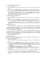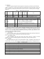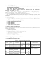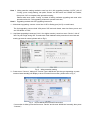
1
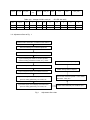
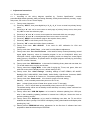
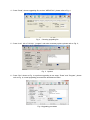
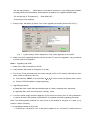
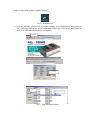
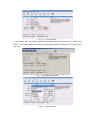
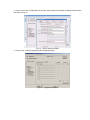
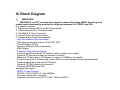
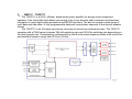
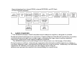
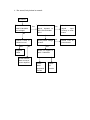
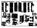
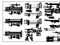
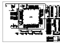
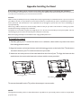
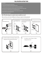
FILE NO.
SERVICE MANUAL
LED-LCD TV
LED-24XR113D
PRODUCT CODE No.
1 682 351 56: PAL-B/G (Australia)
NTSC(AV)
with 3D Function
INPUT
REFERENCE No.:SM0915208
CONTENTS
Safety precautions………………………………………………………………………..… 3
Alignment instructions …………………………….…….………………………………… 5
Software upgrade instructions .................................................................................. 12
Working principle analysis……………………………….………….…………............... 15
Block diagram…………………………………..………………………………….…………17
IC block diagram………………………………………………………………………..……18
Wiring diagram ……………………………………………………………………………. 21
Troubleshooting flow chart ………………………………………………………………..……
22
Schematic diagram………………………………………………………………………… 25
APPENDIX-A: Assembly list
APPENDIX-B: Exploded View
Assembling the Stand
WALL MOUNTING INSTRUCTIONS
Attention: This service manual is only for service personnel to take reference with. Before
servicing please read the following points carefully.
Safety precautions
1. Instructions
Be sure to switch off the power supply before replacing or welding any components or
inserting/plugging in connection wire. Anti static measures must be taken (throughout the entire
production process!):
a) Do not touch here and there by hand at will;
b) Be sure to use anti static electric iron;
c) It’s necessary for the welder to wear anti static gloves.
Please refer to the part list before replacing components that have special safety requirements.
Do not replace with different components with different specs and type at will.
2. LCD servicing precautions
2.1 Screens are different from one model to another and therefore not interchangeable. Be sure to
use the screen of the original model for replacement.
2.2 The operation voltage of LCD screen is 700-825V. Be sure to take proper measures in
protecting yourself and the machine when testing the system in the course of normal operation or
right after the power is switched off. Please do not touch the circuit or the metal part of the module
that is in operation mode. Relevant operation is possible only one minute after the power is
switched off.
2.3 Do not use any adapter that is not identical with the TV set. Otherwise it will cause fire or
damage to the set.
2.4 Never operate the set or do any installation work in bad environment such as wet bathroom,
laundry, kitchen, or nearby fire source, heating equipment and devices or exposure to sunlight etc.
Otherwise bad effect will result.
2.5 If any foreign substance such as water, liquid, metal slices or other matters happens to fall into
the module, be sure to cut the power off immediately and do not move anything on the module lest
it should cause fire or electric shock due to contact with the high voltage or short circuit.
2.6 Should there be smoke, abnormal smell or sound from the module, please shut the power off
at once. Likewise, if the screen is not working after the power is on or in the course of operation,
the power must be cut off immediately and no more operation is allowed under the same
condition.
2.7 Do not pull out or plug in the connection wire when the module is in operation or just after the
power is off because in this case relatively high voltage still remains in the capacitor of the driving
circuit. Please wait at least one minute before the pulling out or plugging in the connection wire.
2.8 When operating or installing LCD please don’t subject the LCD components to bending,
twisting or extrusion, collision lest mishap should result.
2.9 As most of the circuitry in LCD TV set is composed of CMOS integrated circuits, it’s necessary
to pay attention to anti statics. Before servicing LCD TV make sure to take anti static measure and
ensure full grounding for all the parts that have to be grounded.
2.10 There are lots of connection wires between parts behind the LCD screen. When servicing or
moving the set please take care not to touch or scratch them. Once they are damaged the screen
would be unable to work and no way to get it repaired.
If the connection wires, connections or components fixed by the thermotropic glue need to
disengage when service, please soak the thermotropic glue into the alcohol and then pull them
out in case of dagmage.
2.11 Special care must be taken in transporting or handling it. Exquisite shock vibration may lead
to breakage of screen glass or damage to driving circuit. Therefore it must be packed in a strong
case before the transportation or handling.
2.12 For the storage make sure to put it in a place where the environment can be controlled so as
to prevent the temperature and humidity from exceeding the limits as specified in the manual. For
prolonged storage, it is necessary to house it in an anti-moisture bag and put them altogether in
one place. The ambient conditions are tabulated as follows:
Temperature
Humidity
Operation range
0 ~ +50 oC
Storage range
-20 ~ +60 oC
Operation range
20% ~ 85%
Storage range
10% ~ 90%
2.13 Display of a fixed picture for a long time may cause a permanent after-image on the screen,
as commonly called “ghost shadow”. The degree of the after-image varies with the maker of LCD
screen. This phenomenon doesn’t represent failure. This “ghost shadow” may remain in the
picture for a period of time (several minutes). But when operating it please avoid displaying still
picture in high brightness for a long time.
3. Installation precautions
3.1 The front panel of LCD screen is made of glass. When installing it please make sure to put it in
place.
3.2 For service or installation it’s necessary to use specified screw lest it should damage the
screen.
3.3 Be sure to take anti dust measures. Any foreign substance that happens to fall down between
the screen and the glass will affect the receiving and viewing effect
3.4 When dismantling or mounting the protective partition plate that is used for anti vibration and
insulation please take care to keep it in intactness so as to avoid hidden trouble.
3.5 Be sure to protect the cabinet from damage or scratch during service, dismantling or
mounting.
Adjustment Instructions
1
Safety Instructions
1.1 Power supply must be cut off when replacing or welding any component or inserting / pulling out
connective lines;
1.2 Anti-electrostatic measures must be carried out during the whole producing processes!
a) Do not touch IC by hands at will;
b) Use anti-electrostatic iron;
c) Welder must wear anti-electrostatic glove;
1.3 Replacing any component with special safety requirement must refer to component list without
changing its specification and model at will.
2
Adjustment Equipments
Multimeter or osciillograph
VG-849
CA-210
USB
DVD (included HDMI 1.4) or equipments with the same functions
3
Adjustment Processes
3.1 Power voltage test
According to the wiring diagram specified by “Product Specification”, connect power board
assembly, data processing assembly, IR/Key board assembly, backlight board assembly correctly,
supply with power, press button
to power on the TV set.
Test voltage of socket X601 each pin on the main board. Voltage value and range are listed as
Table 1(a) for LCD size ≥26”; voltage value and range are listed as Table 1(b) for non-3D LCD &
LED size ≤24”; voltage value and range are listed as Table 1(c) for LED size ≥26”; voltage value
and range are listed as Table 1(d) for 3D LED size ≤24”;
Table 1(a) Voltage of X601 each pin (LCD size ≥26”)
X601
Pin1,2
3,4
5,6
7,8
9
10
11
12
13
Vol.
24 V±5%
0
12 V±5%
0
≤5.2 V
5 V±5%
5 V±5%
≤5.2 V
≤5.2 V
Function
AMP_PWR
GND
+12 V
GND
PWR_SW
Main 5 V
+5 V STB
BL_PWM
BL_ON
Table 1(b)
Voltage of X601 each pin
(non-3D LCD & LED size ≤24”)
X601
Pin1,2
3,4
5
6
7,8
9
10
11
12
13
Vol.
12 V±5%
0
12 V±5%
NC
0
≤5.2 V
5 V±5%
5 V±5%
≤5 V
≤3.6 V
Function
AMP_PWR
GND
+12 V
NC
GND
PWR_SW
Main 5 V
+5 V STB
BL_PWM
BL_ON
Table 1(c) Voltage of X601 each pin
(LED size ≥26”)
X601
Pin1
2
3
4
5
6,7
8,9
10,11
12,13
Vol.
≤5.2 V
≤5.2 V
5V±5%
5V±5%
≤5.2 V
0
12 V±5%
0
24 V±5%
Function
BL_ON
+5 V
BL_PWM
STB
Table 1(d)
Main 5 V
PWR_SW
GND
Voltage of X601 each pin
+12 V
GND
AMP_PWR
(3D LED size ≤24”)
X601
Pin1,2
3,4
5
6
7,8
9
10
11
12
13
Vol.
12 V±5%
0
12 V±5%
≤3.6 V
0
≤5.2 V
5 V±5%
5 V±5%
≤5 V
≤3.6 V
Function
AMP_PWR
GND
+12 V
3D-EN
GND
PWR_SW
Main 5 V
+5 V STB
BL_PWM
BL_ON
3.2 Adjustment flow as Fig. 1:
Check if EDID、HDCP KEY、FLASH has been written?
General assembly and combined adjustment
White balance adjustment
Input central signal, check TV function (omitted
channel, analog parameters control, etc. ), check
Check accessory and packing
Check AV input, output and relevant functions.
Default settings before shipment
Input Component signal, check YPbPr functions.
Input D-SUB signal, check display and all functions
(such as analog parameter), H/V center, etc..
Input HDMI signal, check display and all functions
(such as analog parameter), H/V center, etc..
Fig. 1
Adjustment flow chart
Check other functions (Radio、LCN、HDMI
ARC/CEC、OAD, etc.)
Check USB multimedia port and Music port.
4
Adjustment Instructions
4.1 The unit adjustments
4.1.1
According to the wiring diagram specified by “Product Specification”, connect
power/backlight board assembly, data processing assembly, IR/Key board assembly correctly, supply
with power, turn on the TV set. Check display
4.1.2
a)
Factory menu instruction
Press key “INPUT”, then press digital keys “2、5、8、0” in turn to enter into primary factory
menu;
b)
Press keys “▲” and “▼” to move cursor to each page of primary factory menu, then press
key “OK” to enter into submenu page;
Press keys “▲” and “▼” to move cursor upward or downward within any one page;
Press keys “◄” and “►” to do adjustment when move cursor to one item;
Press key “MENU” to exit submenu page to the superior factory menu;
Press key “EXIT” to exit factory menu in any case;
c)
d)
e)
f)
g)
h)
Press key “OK” to enter the inferior factory submenu;
Factory menu item: ADC ADJUST to be used for ADC calibration for VGA and
Component;
i)
j)
Factory menu item: Color Temp. to be used for white balance adjustment;
Factory menu item: Fac. Channel Preset to be used for factory channel presetting; central
signal digital frequency value for Australia program is set as CH28(529.5 MHz) and
CH33(564.5 MHz); original digital program presetting could not change as central signal
setting has any modification, so please search for digital program manually by performing
item DTV of menu Channel;
k)
Factory menu item: EEPROM Init to be used for initializing factory data and user date; the
TV set will restart when carrying out the item;
l)
Factory menu item: Aging Mode to be used for aging the TV set; red, green, blue and
white full screen picture displays in turn; default setting is OFF;
m) Factory menu item: Other Settings including settings of MST DEBUG, ISP MODE,
Backlight, SSC, NONLINEAR, Video Quality, Audio Quality, Light Sensor, Overscan, QMAP
ADJUST, VIF1, Aus/Nz All Ch Preset, etc.; no need any adjustment normally.
n)
Factory menu item: Power mode to be used for power-on mode setting;
Standby: to be in standby state when power on the TV set;
Mem: to keep in last power-off state when power on the TV set again;
Force On: the TV set will start up automatically when power on the TV set again;
The default setting will be set as Standby mode and keep in memory unless customer has
special requirement;
o)
Factory menu item: USB SW Update to be used for software updating from USB port;
after U disk containing updating software is inserted into USB port, choose the item to
perform updating process;
p)
Factory menu item: Shipment to be used for initializing user data; the TV set will be
initialized and then a prompt “SUCCESS” will display, initial guided interface will display after
pressing key “exit”;
q)
Please perform EEPROM Init before adjustment for the first time if software has been
upgraded or data have been kept in EEPROM.
4.1.3 ADC calibration for D-SUB channel
a) Switch to D-SUB channel;
b) Press key “INPUT”, then press digital keys “2、5、8、0” in turn to enter into primary factory
menu;
c) Move cursor to item “ADC ADJUST” and press key “OK” to enter into the inferior submenu;
d) Input D-SUB signal (VG-849 Timing:856 (1024×768/60 Hz), Pattern:914 chess square (5
white squares + picture with frame)); move cursor to item “MODE”, press keys “▲” and
“▼” to choose item “RGB”, then move cursor to item “AUTO ADC” and press key “OK” to
perform auto adjustment until a prompt “success” displays;
4.1.4 ADC calibration for Component channel
a) Switch to Component channel;
b) Press key “INPUT”, then press digital keys “2、5、8、0” in turn to enter into primary factory
menu;
c) Move cursor to item “ADC ADJUST” and press key “OK” to enter into the inferior submenu;
d) Input Component signal (VG-849 Timing:972(1080i), Pattern:918 100% color bar); move
cursor to item “MODE”, press keys “▲” and “▼” to choose item “YPbPr”, then move cursor to
item “AUTO ADC” and press key “OK” to perform auto adjustment until a prompt “success”
displays;
4.2 White balance adjustment
For TV model (<24” ), default settings of COOL color temperature is 10000K and
chromatic coordinates is (280、288); referenced settings of Normal color temperature is 8000K
and chromatic coordinates is (295、305); referenced settings of Warm color temperature is 6500K
and chromatic coordinates is (313、329);
For TV model (≥24” ), default settings of COOL color temperature is 12000K and
chromatic coordinates is (272、278); referenced settings of Normal color temperature is 9300K
and chromatic coordinates is (285、293); referenced settings of Warm color temperature is 6500K
and chromatic coordinates is (313、329);
Default setting is Normal.
4.3 Adjustment procedures
The TV set should be working above 30 minutes to be in a stabler state before adjustment. Use
CA-210 BBY channel to adjust white balance;
a) Switch to HDMI channel;
b) Press key “INPUT”, then press digital keys “2、5、8、0” in turn to enter into primary factory
menu;
c)
d)
e)
f)
g)
h)
Move cursor to item “W/B ADJUST” and press key “OK” to enter into the inferior submenu;
Input HDMI signal (VG-849 Timing: 972(1080i),Pattern:921 16 step Gray); move cursor to
item “MODE”, press keys “▲” and “▼” to choose item “HDMI”, then move cursor to item
“TEMPERTURE” and press keys “▲” and “▼” to choose “NORMAL”;
Fix “G GAIN”, adjust “R GAIN, B GAIN” to set 14th chromatic coordinates as (285、293);
Fix “G OFFSET”, adjust “R OFFSET、B OFFSET” to set 4th chromatic coordinates as
(285、293);
To make sure chromatic coordinates of bright scale are (X=285±10,Y=293±10) and
chromatic coordinates of dark scale are (X=285±10,Y=293±10) during adjustemnt;
Move cursor to item “COPY ALL” to copy white balance data to other channels except DTV
channel;
i)
j)
k)
l)
Check if chromatic coordinates of COOL and WARM meet the requirements (permitted error
of COOL bright scale: x±10,y±10, permitted error of COOL dark scale: x±10,y±10;
permitted error of WARM bright scale and dark scale: x±10,y±10); if not, adjust “R_GAIN
/B_GAIN/R_OFF/B_OFF” to be up to the requirements and then save the data;
Perform “Copy All” for COOL /Warm adjustments except DTV channel;
Check if chromatic coordinates of other channels meet the requirements, if not, do
adjustment for nonstandard channel alone in accordance with the same procedures from b)
to j) as HDMI channel’s and then save the data;
Switch to DTV channel, change to 16 step Gray program from central signal source, adjust
white balance in accordance with the same procedures from e) to g); but pay attention not
to perform “COPY ALL”!
m) Inspect all channels after completing adjustment to check if display is normal;
n) Refer to the following rule for adjustment:
B Gain/Offset: adjust B Gain/Offset downward, coordinates of X and Y will increase, adjust B
Gain/Offset upward, coordinates of X and Y will decrease;
R Gain/Offset: adjust R Gain/Offset will affect X value, but affect Lv value slightly, adjust R
Gain/Offset upward, coordinates of X will increase, adjust R Gain/Offset
downward, coordinates of X will decrease;
G Gain/Offset: adjust G Gain/Offset will affect Y value, and affect Lv value greatly, adjust G
Gain/Offset upward, coordinates of Y will increase, adjust G Gain/Offset
downward, coordinates of Y will decrease;
Note: Sanyo customer requires that default color temperature is Normal, adjust white
balance of color temperature Normal and Cool in Dynamic picture mode; for other
customers, please adjust white balance of color temperature Cool in Dynamic picture mode.
5
Function check
5.1 TV functions
Input central signal to RF port, enter into menu Channel first, then search for programs
automatically and check if there is any omitted program; check the speakers output and the picture
display.
5.2 AV port
Input AV signal with formats listed as Table 2 separately, check picture, sound and other functions;
Table 2
No.
Lines per
frame
AV video signal formats
H.- Freq.(kHz)
V.- Freq.(Hz)
Note
1
525
15.734/15.75
59.94/60
NTSC, NTSC4.43,PAL60,PAL-M
2
625
15.625
50
PAL, PAL-N, SECAM
5.3 Component port
Input Component signal from VG-849 with formats listed as Table 3 separately, check picture and
sound in the case of power-on, switching channel, changing mode, etc.;
Table 3
No.
Definition
Component signal formats
H.- Freq.
V.- Freq.
Dot pulse Freq.
(kHz)
(Hz)
(MHz)
Note
1
720×480
15.734/15.75
59.94/60
13.5/13.514
480i (NTSC)
2
720×576
15.625
50
13.5
576i (PAL)
3
720×480
31.469/31.5
59.94/60
27/27.027
480p (NTSC PROG)
4
720×576
31.25
50
27
576p (PAL PROG)
5
1280×720
37.5
50
74.25
720p (50p)
6
1280×720
44.955/45
59.94/60
74.176/74.25
720p (59.94p/60p)
7
1920×1080
28.125
50
74.25
1080i (50i)
8
1920×1080
33.75
59.94/60
74.176/74.25
1080i (59.94p/60p)
9
1920×1080
26.973
23.976
74.176
1080p (23.97p)
10
1920×1080
27
24
74.25
1080p (24p)
11
1920×1080
28.125
25
74.25
1080p (25p)
12
1920×1080
33.716
29.97
74.176
1080p (29.97p)
13
1920×1080
33.75
30
74.25
1080p (30p)
14
1920×1080
56.25
50
148.5
1080p (50p)
15
1920×1080
67.432/67.5
59.94/60
148.35/148.5
1080p (59.94p/60p)
5.4 D-SUB port
Input D-SUB signal from VG-849 with formats listed as Table 4 separately, check picture and
sound; if H./V. of picture displays abnormally, enter into main menu items Picture->Screen->Auto
Adjust to perform auto calibration.
Table 4 D-SUB signal formats
No.
Definition
H.- Freq.
V.- Freq.
Dot pulse Freq.
(kHz)
(Hz)
(MHz)
Note
1
640×480
31.469
59.94
25.175
IBM
2
720×400
31.469
70.086
28.322
IBM
3
640×480
37.861
72.809
31.5
VESA
4
640×480
37.5
75
31.5
VESA
5
800×600
35.156
56.25
36
VESA
6
800×600
37.879
60.317
40
VESA
7
800×600
48.077
72.188
50
VESA
8
800×600
46.875
75
49.5
VESA
9
1024×768
48.363
60.004
65
VESA
10
1024×768
56.476
70.069
75
VESA
11
1024×768
60.023
75.029
78.75
VESA
12
1152×864
67.5
75
108
VESA
13
1280×960
60
60
108
VESA
14
1280×1024
63.98
60.02
108
VESA
15
1280×1024
80
75
135
SXGA
16
1360×768
47.7
60
85.5
WXGA
17
1440×900
55.9
60
106.5
WXGA+ ( Panel National only)
18
1680×1050
65.3
60
146.25
WSXGA+ ( Panel National only)
19
1920×1080
67.5
60
148.5
Full HD
5.5 HDMI port
HDMI port supports all signal formats supported by Component port (Table 3) and D-SUB port
(Table 4), furthermore, it can also support signal with formats listed as Table 5 and Table 5 (video and
audio composition). Check picture and sound in the case of power-on, switching channel, changing
mode, etc.;
Table 5
Digital HDMI signal formats
No.
Definition
H.- Freq.
V.- Freq.
(kHz)
(Hz)
Dot pulse
Freq.
Note
(MHz)
1
720(1440)×480
15.734/15.75
59.94/60
27/27.027
720(1440)×[email protected]/60 Hz,4:3/16:9
2
720(1440)×576
15.625
50
27
720(1440)×576i@50 Hz,4:3/16:9
Table 6
No.
Item
Video & audio signal formats of digital HDMI
Unit
Parameters
Note
Deep color:RGB 4:4:4(24 bit/pixel,30 bit/pixel,36 bit/pixel)、
1
YUV 4:4:4 (24 bit/pixel,30 bit/pixel,36 bit/pixel)、
Video
For 1080p,deep color only supports30 bit/pixel。
YUV 4:2:2(16 bit)、YUV 4:2:2(20 bit)、YUV 4:2:2(24 bit)
2
Audio sample freqence
kHz
32、44.1、48
3
Audio data width
Bit
16、20、24
5.6 USB port
USB ports of some TV models without multimedia processing function are only used for
upgrading software, so functions as follow is only suitable for TV model with multimedia processing
function, and for TV model without multimedia processing function, pay attention not to
connect movable HD to USB port directly!
5.6.1 PVR function
Insert a formatted U disk in which recorded programs have been saved; press key “Record List”
to choose and play programs, check picture, sound and other functions;
5.6.2 Time Shifting function
Insert a formatted U disk with some empty saving space; press key “T.SHIFT” to record
programs, then play the recorded programs and check picture, sound and other functions;
5.6.3 3D signal
Input HDMI signal from VG-871 with formats listed as Table 7 separately, check picture and
sound (32 KHz、44.1 KHz、48 KHz) in the case of power-on, switching channel, changing mode, etc.;
Table 7
3D signal formats
· 1280×720p @ 59.94/60 Hz (Frame Packing, Side-by-Side(Half), Top-and-Bottom)
· 1280×720p @ 50 Hz (Frame Packing, Side-by-Side(Half), Top-and-Bottom)
· 1280×720p @ 23.98/24 Hz (Frame Packing)
· 1280×720p @ 29.97/30 Hz (Frame Packing)
· 1920×1080i @ 59.94/60 Hz (Frame Packing, Side-by-Side(Half))
· 1920×1080i @ 50 Hz (Frame Packing, Side-by-Side(Half))
· 1920×1080p @ 23.98/24 Hz (Frame Packing, Side-by-Side(Half), Top-and-Bottom)
· 1920×1080p @ 29.97/30 Hz (Frame Packing, Top-and-Bottom)
· 1920×1080p @ 59.94/60Hz (Top-and-Bottom)
· 1920×1080p @ 50 Hz (Top-and-Bottom)
5.6.4 Media playing function
Insert a U disk kept files of picture, sound and video, check picture, sound and other functions;
Supported media formats as below:
Photo:JPEG,BMP,PNG,progressive JPEG
Video:H.264 ,MPEG-1,MPEG-2,MPEG2_HD, MPEG4,MPEG4_SD, MPEG4_HD,
MotionJpeg,Divx,Xvid,VC-1,FLV
Audio : WMA , MP3 , M4A(AAC) , HE-AAC/HE-AAC V2 , Dolby Digital (AC-3) ,
MPEG1 Layer II/Musicam ,LPCM,ADPCM,CDDA(*.wav)
5.7 Music port (depending on TV set which contains music port or not)
Input audio signal to side music port (analog audio input) from audio output equipment, check
audio output.
5.8 Other functions check
a) Check timing on/off, sleeping time off, picture/sound mode, OSD, stereo, digital audio port,
etc,;
b) Check pure digital audio programs (RADIO) ;
c) Check logical channel number (LCN);
d) Check HDMI ARC;
e) Check HDMI CEC;
f) Check OAD for special customer;。
6
User Menu Setting before Ex-factory
Enter into LOCK page of user menu and choose submenu item “Restore Factory Default” to perform
presetting before shipment;
a) Clear out all programs;
b) Clear out information of VCHIP,parent control, etc.;
c) Default user analog parameters setting;
d) Recover default password;
e) Set Menu Language as English;
7
Software Upgrading Instructions as Table 8
7.1.1 Upgrading chips are listed as Table 8:
Table 8
Location
Part No.
Software Upgrading Instructions
Software
SMT before
functions
upgrading
Part model
Upgrading methods
Upgrade with ALL100, etc.,
N103/N10
5272532006/
EN25Q32A-100HIP/
2
5272532007
EN25Q32B-104HIP
N105
5272404005
CAT24C04WI-GT3
HDCP KEY
Yes
5272402003
CAT24C02WI
VGA EDID
Yes
N801
5272540003
EN25F40-100GCP
N701
5270615001
PIC12F615I/SN
NB03/N31
4
FLASH
Yes
need write protection, refer to
Note1;
MEMC
module_6M30
3D IE module
Yes
Yes
Upgrade with ALL100, etc.
Note 1
Write protection setting methods: enter into ALL-100 upgrading interface “AUTO”, tick off
“Config”, press “config Setting”, set option “Protect” as “All Protect” and “SRWD” as “Enable”,
then press “OK” to complete write protection setting;
Please make sure option “Config” is ticked off during software upgrading and reset write
protection after ALL-100 upgrading software is opened each time;
Note 2
Upgrading method with ISP upgrading instrument:
1) Main board upgrading: connect 4-core line of ISP to Debug port (X107) on main board;
The Unit upgrading: connect both VGA ports of ISP and main board, enter into factory menu and
set “ISP Mode” as “ON”;
2) Use Mstar upgrading instrument (V4.4.2.0 or higher version), enter into menu “Device”, tick off
“WP Pin pull to high during ISP” to make sure Flash hardware write protection is removed and
erasing process is normal; please refer to Fig.2;
Fig. 2
Write protection setting
3) Press menu “Connect”, dialog box “Device Type is MX25L64” (device type depending on parts
used on board actually) will display to show successful connection; please refer to Fig. 3;
Fig. 3 Device MX25L64 successful connection
If connection is failed, press the first menu “Device” and choose “MX25L64” manually, then press
“Connect”;。
4) Press “Read”, choose upgrading file, such as “MERGE.bin”; please refer to Fig. 4;
Fig. 4
Choosing upgrading file
5) Press “Auto”, tick off “All chip”, “program” and other necessary options; please refer to Fig. 5;
Fig. 5
Options
6) Press “Run” shown as Fig. 4 to perform upgrading in two steps, “Erase” and “Program”, please
refer to Fig. 6; normal upgrading processes are described as follow:
Fig. 6 Upgrading processes
The first step “Erasing…, Flash Status: 03” will last for some time, or the erasing step is failed if
the step passes over immediately; please perform procedure 2) to upgrade software again;
The second step is “Programming…,Flash Status:00”;。
Then prompt “Pass” displays.
7) Prompt “Pass” will display by button “Run” when upgrading succeeds; please refer to Fig. 7;
Fig. 7
A green prompt “Pass” displayed by “Run” when upgrading is successful.
8) Need not exit ISP upgrading interface if there are other TV sets to be upgraded , only procedures
3) and 6) need to be repeated;。
Note 3
Upgrading with USB:
1) Make sure U disk is formatted as FAT32;
2) Copy software file named as “Merge.bin” to U disk;
3) Turn on the TV set and make sure the current channel is ATV or DTV without OSD interface, then
insert U disk to USB port of the unit;
a) First press key “INPUT”, then press keys “2、5、8、0” in turn to enter into primary factory menu;
b) Choose “USB SW Update” to begin upgrading;
4) Upgrading processes:
a) Read data from U disk while data indicator light of U disk is twinkling at the same time;
b) Upgrading flash, then the unit will be in “standby” mode;
5) Cut off the power supply and then restart the TV set, enter into factory menu to verify parameter s
of version and time, then perform “EEPROM Init” to complete the whole upgrading processes.
Note: The USB upgrading methods can not be sure to be suitable for all types of U disks, so try
another U disk if necessary.
7.1.2 Upgrading methods of 3D IR chip
1)Connect ALL-100 and PC, turn on the power supplies of ALL-100 and PC. Double click icon
shown as Fig.8 when system is waiting for input;
Fig. 8 Software icon
2) Press key “DEVICE” shown as Fig. 9 to select company name “MICROCHIP”, then press key
“OK”; select type “MPU/MCU” and corresponding adapter type “PICF12615”, then press key
“Run”; then wait until interface as Fig. 10 displays;
DEVICE
选择厂家 MICROCHIP
选择 MPU/MCU
选择芯片型号:PICF12615
Fig. 9
Chip selection interface
Fig. 10 IC type selection
3)Click menu “File”, select item “Load File to programmer buffer” shown as Fig. 11. Select “Intel
HEX”, “FF” and other options according to settings shown within red frame of Fig. 12, then press
key “OK”;
Fig. 11
Upgrading file selection
Fig. 12
Setup interface
4)Press “Auto” and “Configuration & ID data”, select options according to settings shown within
red frame of Fig.13;
Fig. 13 Option setting interface
5)Press “Run” to begin upgrading after completing setup.
Fig. 14
Upgrading interface
Working Principle of the Unit
1、 ATV
PAL signal flow
Receive RF PAL analog signal and sent it to XC5200C (D/A silicon Tuner controlled by
MSD309PX through I2C bus) to be demodulated, then differential IF signal is send out to
MSD309PX analog demodulator to be demodulated to get analog CVBS video signal and
signal.
CVBS video signal is processed by back-end video decoder, anti-interlacing part, video
main chip
main chip
SIF audio
processor
and zoom controller, then sent to chip 6M30QSR to be processed, in the end LVDS signal is outputted to
drive display panel.
SIF sound signal is processed by back-end demodulator to get analog audio signal, then it is
processed by pre-amplifier, acoustic effect processor and volume controller to get two parts of signals: the
analog part of signal is sent to earphone amplifier MAX9820 to be amplified and then outputted to
earphone jack; the digital part of signal I2S is sent to digital audio power amplifier TAS5711 to be
processed by D/A converter and power amplifier, then outputted to drive speakers.
2、 DVB-T signal flow
Receive RF DVB-T digital signal and sent it to XC5200C (D/A silicon Tuner controlled by main chip
MSD309PX through I2C bus) to be processed by down-frequency converter, then differential IF signal is
send out to main chip MSD309PX digital demodulator to be demodulated, then standard parallel
transmission stream is outputted to back-end demultiplexer and decoder to be processed.
Video channel: demultiplexing digital video signal is processed by MSD309PX decoder and video
processor, then sent to chip 6M30QSR to be processed, in the end LVDS signal is outputted to drive
display panel;
Audio channel: demultiplexing digital audio signal is processed by MSD309PX decoder and audio
processor, then double-sound-track analog audio signal (stereo) is outputted to MSD309PX to be
processed by preamplifier, acoustic effect processor and volume controller to get two parts of signals: the
analog part of signal is sent to earphone amplifier MAX9820 to be amplified and then outputted to
earphone jack; the digital part of signal I2S is sent to digital audio power amplifier TAS5711 to be
processed by D/A converter and power amplifier, then outputted to drive speakers.
3、 AV input signal flow
AV video signal is inputted to main chip MSD309PX to be processed by video decoder,
anti-interlacing part, video processor and zoom controller, then sent to chip 6M30QSR to be processed, in
the end LVDS signal is outputted to drive display panel;
AV audio signal is processed by voltage divider, resistance matcher and AC coupler, then sent to
main chip MSD309PX to be processed by acoustic effect processor and volume controller to get two parts
of signals: the analog part of signal is sent to earphone power amplifier MAX9820 to be amplified and
then outputted to earphone jack; the digital part of signal I2S is sent to digital audio power amplifier
TAS5711 to be processed by D/A converter and power amplifier, then outputted to drive speakers.
4、 D-SUB/YPbPr input signal flow
D-SUB、YPbPr video signal is inputted to main chip MSD309PX to be processed by A/D converter,
video decoder, anti-interlacing part, video processor and zoom controller, then LVDS signal is outputted to
drive display panel;
D-SUB、YPbP audio signal is processed by voltage divider, resistance matcher and AC coupler, then
sent to main chip MSD309PX to be processed by acoustic effect processor and volume controller to get
two parts of signals: the analog part of signal is sent to earphone power amplifier MAX9820 to be
amplified and then outputted to earphone jack; the digital part of signal I2S is sent to digital audio power
amplifier TAS5711 to be processed by D/A converter and power amplifier, then outputted to drive
speakers.
5、 HDMI input signal flow
HDMI video signal is inputted to main chip MSD309PX to be processed by video decoder, video
processor and zoom controller, then sent to chip 6M30QSR to be processed, in the end LVDS signal is
outputted to drive display panel;
HDMI audio signal is sent to main chip MSD309PX to be processed by audio decoder, pre-amplifier,
acoustic effect processor and volume controller to get two parts of signals: the analog part of signal is sent
to earphone power amplifier MAX9820 to be amplified and then outputted to earphone jack; the digital
part of signal I2S is sent to digital audio power amplifier TAS5711 to be processed by D/A converter and
power amplifier, then outputted to drive speakers.
6、 SPDIF input signal flow
SPDIF audio signal is sent to main chip MSD309PX to be processed by acoustic effect processor,
volume controller and digital audio coder, then is outputted.
7、 Brief instruction on unit functions
MPEG-2 MP@HL、H.264 Main and High profile up to Leve4.0 Decoding
MPEG、Dolby Digital(AC-3)、AAC Digital Audio Decoding
3D comb filter
Low consumed power in standby mode(≤1W)
Audio power amplifier (D type) with HI-FI acoustic output
High quality transformation from interleaved scanning to line-by-line scanning
Realizing real integrative functions
- build integration
- integrative TUNER(integrating analog with digital)
- integrative searching-program function
- integrative OSD interface
Main parts of the unit:
LCD panel: 31.5 inch AUO T315HW04 VD (1920X1080)
Main chip:MStar MSD309PX-LF
Silicon TUNER:XCeive XC5200C
DDR:NANYA NT5TU32M16DG_AC
Audio power amplifier (D type):TI TAS5711
FLASH:EN25Q32B-104HIP
8、External ports of the unit:
One group of Video input and RCA L/R input
Three group of HDMI input
One group of VGA input
One group of audio input for VGA and DVI (Mini Phone Jack)
One group of YPBPR input and RCA L/R input
One group of RF
One group of RS232 (Mini Phone Jack)
One group of Earphone output (Mini Phone Jack)
One group of SPDIF (coaxial) output
One group of USB
Block Diagram
RF
XC5200C
Silicon
Tuner
VIF
LVDS
SIF
HDMI1 w/ARC
I2S
HDMI2
MEMC
6M30QSR
TAS5711
Audio
Amplfier
HDMI3
VGA
MSD309PX-LF
YPbPr
DDR2
512Mbit X 2PCS
Video In
YPbPr Audio In
Flash
AV Audio In
VGA Audio In
SPDIF IN
IR
USB
RS-232
MAX232
POWER
SUPPLY
KEY
IC Block Diagram
1、
MSD309PX
MSD309PX, an SOC solution that supports channel decoding, MPEG decoding, and
media-centre functionality enabled by a high performance AV CODEC and CPU
Key features include:
1. Digital and Analog DVB Front-End Demodulator
2. A Multi-Standard A/V Format Decoder
3. The MACE-5 Video Processor
4. Home Theater Sound Processor
5. Peripheral and Power Management
High Performance Micro-processor
. Ultra high speed/performance 32-bit RISC CPU
. Two full duplex UARTs
. Supports USB and ISP programming
. DMA Engine
Transport Stream De-multiplexer
. Supports parallel and serial TS interface, with or without sync signal
. Supports TS input and output for external CI module
. Maximum TS data rate is 104 Mb/sec for serial or 16 MB/sec for parallel
. 32 general purpose PID filters and section filters for each transport stream de-multiplexer
. Supports additional audio/video/PCR filters
. Supports TS DMA channel for time-shift
. Supports 3DES/DES and AES
encryption/decryption
MPEG-2 Video Decoder
. ISO/IEC 13818-2 MPEG-2 video MP@HL
. Automatic frame rate conversion
. Supports resolution up to HDTV (1080i, 720p) and SDTV
MPEG-4 Video Decoder
. ISO/IEC 14496-2 MPEG-4 ASP video decoding
. Supports resolutions up to HDTV (1080p@30fps)
. Supports DivX1 Home Theater & HD profiles Optional
. Supports VC-1Optional, FLV video format decoding
H.264 Decoder
. ITU-T H.264, ISO/IEC 14496-10 (main and high profile up to level 4.1) video decoding
. Supports resolutions for all DVB, ATSC, HDTV, DVD and VCD
. Supports resolution up to 1080p@30fps
. Supports CABAC and CAVLC stream types
. Processing of ES and PES streams, extraction and provision of time stamps
. Up to 40 Mbits bitrate (Blu-ray spec.)
Hardware JPEG
. Supports sequential mode, single scan
. Supports both color and grayscale pictures
. Following the file header scan the hardware decoder fully handles the decode process
. Supports programmable Region of Interest (ROI)
. Supports formats: 422/411/420/444/422T
. Supports scaling down ratios: 1/2, 1/4, 1/8
. Supports picture rotation
NTSC/PAL/SECAM Video Decoder
. Supports NTSC-M, NTSC-J, NTSC-4.43, PAL (B,D, G, H, M, N, I, Nc), and SECAM standards
. Automatic standard detection
. Motion adaptive 3D comb filter
. Five configurable CVBS & Y/C S-video inputs
. Supports Teletext, Closed Caption (analog CC 608/ analog CC 708/digital CC 608/digital CC 708),
V-chip and SCTE
Multi-Standard TV Sound Processor
. SIF audio decoding
. Supports BTSC/A2/EIA-J demodulation
. Supports NICAM/FM/AM demodulation
. Supports MTS Mode Mono/Stereo/SAP in BTSC/EIA-J mode
. Supports Mono/Stereo/Dual in A2/NICAM mode
. Built-in audio sampling rate conversion (SRC)
. Audio processing for loudspeaker channel, including volume, balance, mute, tone, EQ, virtual
stereo/surround and treble/bass controls
. Advanced sound processing options available, for example: SRS1, BBE2, QSound3, Audyssey4
. Supports digital audio format decoding:
- MPEG-1, MPEG-2 (Layer I/II), MP3, Dolby Digital (AC-3), AAC-LC
- Supports Optional Dolby Digital Plus, Dolby Pulse, and MS10 multistream decoder, including Dolby
Digital Encoder for transcoding streams to Dolby Digital 5.1 (DDCO)
. Supports MPEG Audio, Dolby Digital, Dolby Digital Plus format AD (Audio Description)
. Supports PVR and time-shifting
Audio Interface
. One SIF audio input interface with minimal external saw filters
. Four L/R audio line-inputs
. Two L/R outputs for main speakers and additional line-outputs
. Supports stereo headphone driver
. I2S digital audio input & output
. S/PDIF digital audio output
. HDMI audio channel processing
. Programmable delay for audio/video synchronization
Analog RGB Compliant Input Port
. Three analog ports support up to 1080P
. Supports PC RGB input up to SXGA@75Hz
. Supports HDTV RGB/YPbPr/YCbCr
. Supports Composite Sync and SOG Sync-on-Green
. Automatic color calibration
. AV-link support
Analogue RGB Auto-Configuration & Detection
. Auto input signal format and mode detection
. Auto-tuning function including phasing, positioning, offset, gain, and jitter detection
. Sync Detection for H/V Sync
DVI/HDCP/HDMI Compliant Input Port
. Three HDMI/DVI Input ports
. HDMI 1.3 Compliant
. HDCP 1.1 Compliant
. 225MHz @ 1080P 60Hz input with 12-bit Deep-color support
. CEC support
. Single link DVI 1.0 compliant
. Robust receiver with excellent long-cable support
MStar Advanced Color Engine (MStarACE-5)
. 10/12-bit internal data processing
. Fully programmable multi-function scaling engine
- Nonlinear video scaling supports various modes including Panorama
- Supports dynamic scaling for VC-1
. High-Quality DTV video processor
- 3D motion video deinterlacer with motion object stabilizer
- Edge-oriented deinterlacer with edge and artifact smoother
- Automatic 3:2/2:2/M:N pull-down detection and recovery
- 3D multi-purpose noise reduction for DTV or lousy air/cable input
- MPEG artifact removal including de-blocking and mosquito noise reduction
- Arbitrary frame rate conversion
. MStar Professional Picture Enhancement:
- Dynamic brilliant and fresh color
- Dynamic Blue Stretch
- Intensified contrast and details
- Dynamic Vivid Skin
- Dynamic sharpened Luma/Chroma edges
- Global and local dynamic depth of field perception
- Accurate and independent color control
- Supports sRGB and xvYCC color processing
- Supports HDMI 1.3 deep color format
. Programmable 12-bit RGB gamma CLUT
Output Interface
. Single/dual link 8/10-bit LVDS output
. Supports panel resolution up to Full-HD (1920x1080) @ 60Hz
. Supports TH/TI format
. Supports dithering options to 6/8-bit output
. Spread spectrum output for EMI suppression
CVBS Video Encoder
. Supports all NTSC/PAL TV Standard
. Stand-alone scaling engine
. Programmable Hue, Contract, Brightness
. Supports TTX/CC/WSS output
CVBS Video Output
. Allows CVBS output of all source inputs
3D-like Graphics Engine
. Hardware Graphics Engine for responsive interactive applications
. Supports point draw, line draw, rectangle draw/fill, text draw and trapezoid draw
. BitBlt, stretch BitBlt, trapezoid BitBlt, mirror BitBlt and rotate BitBlt
. Supports alpha and destination alpha compare
. Raster Operation (ROP)
. Support Porter-Duff
VIF Demodulator
. Compliant with NTSC M/N, PAL B, G/H, I, D/K, SECAM L/L' standards
. Audio/Video dual-path processor
. Stepped-gain PGA with 25 dB tuning range and 1 dB tuning resolution
. Maximum IF gain of 37 dB
. Programmable TOP to accommodate different tuner gain and SAW filter insertion loss to optimize noise
and linearity performance
. Multi-standard processing with single SAW
. Supports silicon tuner low IF output architecture
DVB-T Demodulator
. Digital carrier frequency offset correction: ±500KHz
. Optimised for SFN channels with pre/post-cursive echoes inside/outside the guard
. Acquisition range ±857kHz includes up to 3x ±1/6 MHz transmitter offset
. Meets Nordig Unified 1.0.3, D-Book 5.0, EICTA E-Book/C-Book test requirement
. ±400kHz internal carrier offset recovery range
. 6.8 usecs echo cancellation at 7 Msym/s
. Supports IF, low-IF, zero-IF inputs
. Ultra-fast automatic blind UHF/VHF channel scan (constellations and symbol rate)
Connectivity
. Two USB 2.0 host ports
. USB architecture designed for efficient support of external storage devices in conjunction with off air
broadcasting
Miscellaneous
. DRAM interface supporting two 16-bit DDR2 @ 1066MHz
. Supports PVR
. Supports Common Interface for conditional access support
. Bootable SPI interface with serial flash support
. Parallel interface for external OneNAND and NAND flash support
. Power control module with ultra low power MCU available in standby mode
. 523-ball LFBGA package
. Operating Voltages: 1.26V (core), 1.8V (DDR2),
2.5V and 3.3V (I/O and analog)
2、
TUNER IC XC5200C
The Single-Chip Multi-Standard Tuner XC5200C supports all analog TV formats transmitted
worldwide in the 42-1000 MHz band on either cable or terrestrial broadcast channels. It implements
on-chip tuning, and channel filtering without external (SAW) filters and has no manually tunable parts.
The broadband tuner converts the selected channel into an Intermediate Frequency (IF), which is
thensampled by an internal high-resolution analog-to-digital converter (A/D) for further processing.
The IF signals are filtered using a standard-dependent high-rejection channel filter and converted to a
userprogrammable output frequency. At the output of the D/A converter, the TV signal is low-pass filtered
using a high-performance smoothing filter and input to a variable gain amplifier. The IF output amplifier
gain can be controlled via an external analog signal on Vagc.
The XC5200C architecture is summarized in Figure 1. XC5200C Block Diagram.
3、
AMP IC
TAS5711
The TAS5711 is a 20-W, efficient, digital audio power amplifier for driving stereo bridge-tied
speakers. One serial data input allows processing of up to two discrete audio channels and seamless
integration to most digital audio processors and MPEG decoders. The device accepts a wide range of
input data and data rates. A fully programmable data path routes these channels to the internal speaker
drivers.
The TAS5711 is an I2S slave-only device receiving all clocks from external sources. The TAS5711
operates with a PWM carrier between 384-kHz switching rate and 352-KHz switching rate depending on
the input sample rate. Oversampling combined with a fourth-order noise shaper provides a flat noise floor
and excellent dynamic range from 20 Hz to 20 kHz.
4、
MEMC IC 6M30QSR
GENERAL DESCRIPTION
The MST6M30QSR is a highly integrated ASIC for doubling the frame rate of the LVDS video input to
provide a conversion from 50Hz to 100Hz or 60Hz to 120Hz. The MST6M30QSR comprises dual-channel
LVDS receiver, film source detection and inversion, motion frame rate conversion, color space
conversion and management, and single/dual/quad-channel LVDS output. The LVDS receiver and
transmitter in MST6M30QSR support spread spectrum for EMI reduction. With MFCTRE technology, the
MST6M30QSR provides clear and halo-free moving picture quality without motion blur or judder. With
individual RGB gamma correction, the MST6M30QSR is capable to optimize the panel with best display
quality and color saturation, and ideally suited to work with front-end ATV or DTV chip and WUXGA
100/120Hz panels.
FEATURES
Input Interface
. Single/dual channel 8/10 bit LVDS input
. Each input LVDS channel frequency supports up to 100 MHz
. One channel input supports up to WXGA (1366x768)
. Two channel inputs support up to WUXGA (1920x1200)
. Input mode supports JEIDA / VESA mode
. Image capturing window is defined by DE signal
. Supports flexible aging mode
. Supports 3D LR side by side content
. Supports 3D Top bottom content
. Supports 3D Frame packing mode
. Supports 3D Frame alternative mode
. Supports 3D Line alternative mode
Output Interface
. Single/dual/quad link 8/10 bit LVDS output
. Each output LVDS channel frequency supports up to 100 MHz
. Supports two channel LVDS up to WXGA (1366x768) @ 120Hz
. Supports four channel LVDS up to 1920x1080 @ 120Hz
. Supports 2/4 phase output
. Supports left-right screen partition
. Supports TH/TI format
. Supports dithering options
. Spread spectrum output frequency for EMI suppression
. Support 60/120Hz 3D passive panel (line alternative mode)
. Support 240Hz panel (two chip solution)
. Support active shutter glasses control
Video Processing
. MFCTRE (Motion Frame Conversion – Professional Edition) supports:
. Wider searching range
. Refined judder-free motion video and film
. Motion blur elimination to improve MPRT
. Advanced halo and artifact elimination
. Output frame rate 50/60/100/120 f/sec
. Supports MFCTRE under WUXGA resolution
. Automatic 2:2 / 3:2 film mode detection
. Supports 2:2 / 3:2 pull-down reverse processing
. Support 1080p 24fps 5:5 pull-down
. Supports 10-bit 4:4:4 processing
. Brightness contrast saturation adjustment
. White balance adjustment
. Supports Gamma correction per bit and FRC function for 16.7M color selection
. Supports black insertion
. Supports OSD area handling
. Splits screen demo for motion frame conversion
Miscellaneous
. Embedded 8-bit Microcontroller
. Supports 16-bit DDR2 interface
. Supports I2C, SPI, PWM, and GPIOs
. Supports booting from internal SRAM, external EEPROM, and SPI flash
. 216-pin EPLQFP package
5、
AUDIO IC MAX9820
The MAX9820 Windows Vista®-compliant stereo headphone amplifier is designed for portable
Equipment where board space is at a premium. It features Maxim’s DirectDrive® architecture to produce
a ground-referenced output from a single supply, eliminating the large output-coupling capacitors
required by conventional single-supply headphone amplifiers.
The MAX9820 features an undervoltage lockout that prevents over discharging of the battery
During brownout conditions, click-and-pop suppression that eliminates audible transients on startup, a
low-power shutdown mode, and thermal-overload and short-circuit protection. Additionally, the MAX9820
suppresses RF radiation received by input and supply traces acting as
antennas and prevents the amplifier from demodulating the coupled noise.
Wiring Diagram
Troubleshooting Block Diagram
1.Panel doesn’t light up.
Supply with power,
check if red indicator
lights up in STANDBY
state?
Yes
Press key POWER
on remote control or
the
unit,
check
indicator.
No
Check if 5V is supplied
to X601-PIN11 ?
Blue
No
Check
circuits
board.
Red
Check if level of
X601-PIN13
on
main board is high?
STANDBY
on
power
Yes
No
Check
board.
backlight
Check
power
control circuits on
main board.
No
Check if level of
X601-PIN9 on main
board is high?
Yes
Check
power
control circuits on
main board.
Check power
board.
2.No picture, but backlight is normal:
Can the TV set be
controlled by keys on
remote control or the unit?
Yes
Press key MENU,
can OSD display
normally?
Yes
No
No
Yes
No
有
Enter into factory menu to initialize
EEPROM, then cut off main power
and then turn on the TV set again,
check if there is picture?
Yes
Readjust the
main board.
Replace the main
board
Do no
TVchannel
have picture at
all?
No
3.No sound, but picture is normal:
No sound
Check if level of
N607-PIN19&25
are all high?
No
Yes
Check if there is
signal inputted to
N607-PIN15&20&21
&22 ?
No
Check
IIS
(signal
input
circuits) on main
board.
No
Check +12V on
power board.
Yes
Check if level of
V606-b is low?
Yes
Check power voltage
of N607.
No
Replace
V606
Check Reset &
Mute circuits of
power amplifier.
Yes
Check IIC signal of
N607- PIN23&24.
Check
N607
peripheral
circuits
Check
IIC
circuits
Power board
Backlight
APPENDIX-A: Main assembly 9224KI6812
NAME
Main board
NO.
XI6KI00701B0
LED-24XR113D
MAIN COMPONENT AND IT'S NO.
N101
MSD309PX-LF
5270309003
N607
TAS5711
5275711001
N103
EN25Q32B-104HIP
5272532007
N803
MST6M30QSR-LF
5270630001
N312
MAX9820
5279820001
IR board
XI635KI00903
Key board
XI635MS00801
Power board
XI6KI00720B0
Remote control
XI6010900802
RC-908-0A
Panel
XI5203248505
V236H3-LS1
APPENDIX-B: Exploded view (LED-24XR113D )
PART LIST OF EXPLODED VIEW
REF.No.
1
2
3
4
5
6
7
8
9
10
11
12
13
14
15
16
DESCRIPION
Front cabinet assembly
Display panel
Main board connective bar (up)
Main board assembly
Power board assembly
Back cover assembly
Pedestal assembly
Standing pole
Interface baffle (down)
Interface baffle (size)
Main board connective bar (down)
Key board assembly
Powr cord bracket
3D IE assembly
Speaker assembly
IR assembly
Note: Design and specification are subject to change without notice.
PART LIST
LED-24XR113D ver.1.0
REF.No. PARTS No.
1
XI6624680060
2
XI5203248505
3
XI58A0B92700
4
XI6KI00701B0
5
XI6KI00720B0
6
XI672468H050
7
XI6150111000
8
XI58D0030310
9
XI5810D78020
10
XI5810F77910
11
XI58A0B92600
12
XI635MS00801
13
XI58B004361A
14
XI6KI00707A0
15
XI6170894000
16
XI635KI00903
17
XI6010900802
18
XI5944039670
DESCRIPION
Front cabinet assembly
Display panel
Main board connective bar (up)
Main board assembly
Power board assembly
Back cover assembly
Pedestal assembly
Standing pole
Interface baffle (down)
Interface baffle (size)
Main board connective bar (down)
Key board assembly
Powr cord bracket
3D IE assembly
Speaker assembly
IR assembly
Remote control
User manual
Only the parts in above list are used for repairing.
Other parts except the above parts can't be supplied.
Q'TY REMARK
1
1 V236H3-LS1
1
1
1
1
1
1
1
1
1
1
1
1
1
1
1
1
Appendix: Installing the Stand
If the stand is provided, please read these instructions thoroughly before attempting this installation.
You must install your TV into the stand in order for it to stand upright on a cabinet or other flat surface. If you intend to mount your TV
on a wall or other vertical surface, you must remove the stand column.
Cautions:
Make sure that you handle your TV very carefully when attempting assembly or removal of the stand. If you are not sure of
your ability to do this, or of your ability to use the tools necessary to complete this job, refer to a professional installer or
service personnel. The manufacturer is not responsible for any damages or injuries that occur due to mishandling or
improper assembly.
When using a table or bench as an aid to assembly, make sure that you put down a soft cushion or covering to prevent
accidental scratching or damage to your TV's finish.
The speaker is not intended to support the weight of your TV. Do not move or handle your TV by the speaker. This can
cause damage to your TV that is not covered by the manufacturer's warranty.
Before attempting assembly or removal of the stand, unplug the AC power cord.
To install the stand:
1. Carefully place your TV screen face-down on a cushioned, clean surface to protect the screen
from damages and scratches.
2. Align the locators on the stand column with the locating grooves on the back of the TV and secure
the stand column to your TV with the three screws provided.
3. Make sure the wide portion of the stand base faces the front of your TV. Align the base with the
stand column, then secure the base to the column with the screw provided.
Stand column
Locating grooves
Stand column
Stand base
To remove the stand from the TV, perform these steps in reverse order.
NOTE:
The appearance of this product in these illustrations may differ from your actual product, and is for comparative
purposes only.
WALL MOUNTING INSTRUCTIONS
Safety Precautions:
1. Be sure to ask an authorized service personnel to carry out setup.
2. Thoroughly read this instruction before setup and follow the steps below precisely.
3.The wall to be mounted should be made from solid materials. Only use accessories supplied by the manufacturer.
4.Very carefully handle the unit during setup. We are not liable for any damage or injury caused by mishandling or improper installation.
5.Be sure to place the unit on a stable and soft platform which is strong enough to support the unit.
6.Do not uplift the speaker when moving the display. The appearance of the unit may different from the actual ones.
7.Design and specifications are subject to change without notice.
8. Retain these instructions for future reference.
Note: All the wall mounting parts are optional and may be unavailable in your model.
Below we will show you how to mount the Display on the wall using our company’s wall mounting components.
1
2
Take out these parts from the box.
Screw 4pcs expansion bolts to fix
the wall mounting bracket on the
wall.
If your wall is a wooden structure, please
fix the wall mounting bracket on the wall
with 8 pcs wood screws.
3
Wall Mounting
Component
(including bracket
and connector)
Use the 4pcs M4 screws to fix the wall
mounting connector to the rear of the
display unit.
Wall
Wall
Expansion Bolt
Wall Mounting Connector
Wood Screw
Wall Mounting Bracket
M4 Screw
Fig. 1
4
Wall Mounting Bracket
Fig. 2a
Fully insert the two insertions on the wall mounting connector into the
locating grooves on the wall mounting bracket from top to bottom end.
Fig. 2b
5
Fig. 3
Use screwdriver to revolve the Clasper to the Positioner
following the direction of the arrow.
Clasper
Positioner
Fig. 4
Fig. 5
August 2011