1
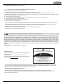
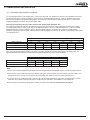
Installation, operating and maintenance ECOLEAN 25 - 200 kW MIL113E-0311 02-2012 Original manual translation Air cooled liquid chiller TABLE OF CONTENTS Page PREFACE 2 DATA PAGE FOR UNIT COMMISSIONING 4 1. 2. General characteristics 1.1 Technical data 5-7 1.2 Electrical data 8 1.3 Component 9 1.4 Operation limits 10 -11 1.5 Pressure drop in the water system 12 - 13 1.6 Hydraulic system data 14 - 16 1.7 Piping drawings 17- 20 1.8 Dimensions 21 - 23 INSTALLATION 2.1 Site and shipping guidance 24 2.2 Unit lifting 24 2.3 Antivibration mounting 25 2.4 Installation clearances 26 2.5 Unit installation 27 - 28 2.6 Electrical connections 3. 4. 29 COMMISSIONING AND OPERATION 3.1 Steps to follow for commissioning the units 30 3.2 Checking the water flow rate 31 3.3 Water analysis 32 MAINTENANCE 4.1 Preventive maintenance 33 4.2 Corrective maintenance 33 - 34 4.3 Failure diagnosis 34 Our company’s products comply with European standards. The manufacturing of EcoLeanTM answers to ISO9001 control quality system. Units are certificated by EUROVENT Lennox have been providing environmental solutions since 1895, our range of EcoLeanTM reversible chillers continues to meet the standards that have made LENNOX a household name. Flexible design solutions to meet YOUR needs and uncompromising attention to detail. Engineered to last, simple to maintain and Quality that comes as standard. Information on local contacts at www.lennoxeurope.com. All the technical and technological information contained in this manual, including any drawing and technical descriptions provided by us, remain the property of Lennox and must not be utilised (except in the operation of this product), reproduced, issued to or made available to third parties without the prior written agreement of Lennox. The specifications and technical characteristics in this booklet are given for information purposes. The manufacturer reserves the right to modify them without prior notice or obligation to modify in a similar manner, the equipments previously supplied. •• PREFACE Please read this operating manual prior to commissioning the EcoLean™ chiller. Familiarize yourself with the operation and control of the EcoLean™ chiller and closely follow the instructions. We would like to stress the importance of training with respect to the correct handling of the chiller. Please consult Lennox on the options available in this field. It is important that this manual be stored in a permanent location in the vicinity of the EcoLean™ chiller. For the sake of clarity, important items in this manual are shown as follows: Text This manual contains important instructions regarding the commissioning of the EcoLean™ chiller. It also includes important instructions to prevent personal injury and damage to the machine during operation. Furthermore, in order to promote fault-free operation of the chiller, maintenance information has been included. Please do not hesitate to contact one of our employees should you require further information on specific chiller subjects. Order related documentation will be forwarded under separate cover. This documentation consists of: - CE declaration - Operating manual for control system - Installation Operating manual - Wiring diagram - Unit detail are given on unit nameplate Important general instructions FOR NETHERLAND: the STEK logbook, including the required certificates will be handed over by the installation technician or left with the machine following commissioning by Lennox. The data published in this manual is based on the most recent information available. It is supplied conditional to later modifications. We reserve the right to modify the construction and/or design of our EcoLean™ chillers, at any time, without prior notification or obligation to adapt previous supplies accordingly. Danger of damage to the chiller Any work on the Chiller should be carried out by trained and licensed competent technician. The following risks are present on the unit: - risk of electrical shock. - risk of injury from rotating parts. - risk of injury from sharp edges and heavy weight. - risk of injury from high pressure gas. - risk of injury from high and low temperatures components. •• The unit must be installed in accordance with local safety codes andregulations and can only be used in a well ventilated area. Please readcarefully the manufacturer’s instructions before starting this unit All work on the unit must be carried out by a qualified and authorised employee. Non-compliance with the following instructions may result in injury or serious accidents. Work on the unit: The unit shall be isolated from the electrical supply by disconnection and locking using the main isolating switch. Workers shall wear the appropriate personal protective equipment (helmet, gloves, glasses,etc.). Electrical system: Electrical connections can become loose during transport. Please check them before starting-up the unit Compressors with specific rotation direction. Check the correct rotation direction of the fan before closing the compressor circuit breakers. If the direction is incorrect, the phases must be reversed at the head of the main switch. Work on electric components shall be performed with the power off (see below) by employees having valid electrical qualification and authorisation. Refrigerating circuit(s): After more than 12 hours of power cut, the cranckcase heater (compressor) should be powered for 5 hours before any return to service. Non-compliance with this instruction can cause deterioration of the compressors. Monitoring of the pressures, draining and filling of the system under pressure shall be carried out using connections provided for this purpose and suitable equipment. To prevent the risk of explosion due to spraying of coolant and oil, the relevant circuit shall be drained and at zero pressure before any disassembly or unbrazing of the refrigerating parts takes place. There is a residual risk of pressure build-up by degassing the oil or by heating the exchangers after the circuit has been drained. Zero pressure shall be maintained by venting the drain connection to the atmosphere on the low pressure side. The brazing shall be carried out by a qualified brazier. The brazing shall comply according to code ASME section IX following the procedures specific. Before starting up: -Test the circuit to the maximum working pressure(see the nameplate) -Verifify the operation of the high pressure swich. -Check the piping and the components of the refrigerant circuit. Replacing components: In order to maintain CE marking compliance, replacement of components shall be carried out using spare parts, or using parts approved by Lennox. Only the coolant shown on the manufacturer’s nameplate shall be used, to the exclusion of all other products (mix of coolants, hydrocarbons, etc.). CAUTION: In the event of fire, refrigerating circuits can cause an explosion and spray coolant gas and oil. •• DATA PAGE FOR UNIT COMMISSIONING Unit: Serial no. : Control panel identification code Installation address: Installer: Installer tel. : Installer address: Date of commissioning: Checks: Supply voltage: Rated voltage of the unit : YES NO Unit on rubber antivibration mounts General power supply connection Control panel connection (option) Compressor oil level indicator Hydraulic connection Purged of the installation DATA INPUT Air Input Temperature, Coil °C Water Output Temperature °C Water Input Temperature °C COOLING CYCLE HEATING CYCLE COOLING CYCLE HEATING CYCLE High Pressure Low Pressure ELECTRIC POWER CONSUMPTION Compressor 1 A Fan 1 A Compressor 2 A Fan A Compressor 3 A Fan 3 A Compressor 4 A Fan 4 A Options Installed: Comments: •• 1.- GENERAL CHARACTERISTICS 1.1.- TECHNICAL DATA EA C 100 3 S M 4 HY LN Type of unit EcoLeanTM C: Cooling only units R: Heat pump units Approximately capacity in kW --- : Standard version LN: Low noise version SLN: Super low noise version --- : Standard version HY: Hydraulic version HN: Hydronic version Number of compressors 4 : Revision 4 S: Standard version F: High pressure version M: Refrigerant R410A COOLING ONLY EAC MODELS kW Cooling capacity (*) Compressor 0251SM 0291SM 0351SM 0431SM 0472SM 0552SM 0672SM 0812SM 22,1 25,9 32,0 37,6 44,1 50,7 63,4 75,4 Nr/type Hydraulic connections Min. water rate Net weight 1 / scroll 2 / scroll 1 1/2"G 2"G 3 m /h 3,16 3,72 4,4 5,3 6,05 7,07 8,6 10,39 Standard kg 238 246 263 292 470 482 518 562 High pressure kg 253 261 278 298 500 512 548 592 kg 5,5 6,1 7,6 9 11 12,2 15,5 19,5 1003SM 1103SM 1203SM 1303SM 1403SM 1604SM 1804SM 2104SM 88,2 102 112 126 139 149 174 199 Refrigerant EAC MODELS kW Cooling capacity (*) Compressor Nr/type 3 / scroll 4 / scroll 2 1/2"G DN80 Hydraulic connections Min. water rate Net weight m /h 3 12,38 13,9 15,76 17,48 18,86 21,06 24,77 28,3 Standard kg 640 809 938 990 1019 1328 1683 1703 High pressure kg 680 849 978 1030 1059 1368 1763 1783 kg 23,5 26 27 30 33,7 36,2 45 47 Refrigerant HEAT PUMP EAR MODELS 0251SM 0291SM 0351SM 0431SM 0472SM 0552SM 0672SM 0812SM kW 22,1 25,9 32,0 37,6 44,1 50,7 63,4 75,4 Heating capacity (**) Nr/type 23,6 27,6 33,6 37,8 47,8 54,7 68,0 75,7 Compressor Nr/type Cooling capacity (*) Hydraulic connections Min. water rate Net weight 1 / scroll 2 / scroll 1 1/2"G 2"G 3 m /h 3,16 3,72 4,4 5,3 6,05 7,07 8,6 10,39 kg 243 251 271 300 480 492 534 578 High pressure kg 258 266 286 305 510 522 564 608 kg 5,8 6,5 8 9,5 12,5 13,5 16 19,3 Standard Refrigerant EAR MODELS 1003SM 1103SM 1203SM 1303SM 1403SM 1604SM 1804SM 2104SM kW 88,2 102 112 126 139 149 174 199 Heating capacity (**) Nr/type 95,0 108 118 130 143 159 180 205 Compressor Nr/type Cooling capacity (*) 3 / scroll Hydraulic connections 2 1/2"G Min. water rate Net weight Refrigerant 4 / scroll m3/h Standard 12,38 13,9 DN80 15,76 17,48 18,86 21,06 24,77 28,3 kg 663 831 964 1016 1045 1347 1703 1723 High pressure kg 703 871 1004 1056 1085 1387 1783 1803 kg 23,3 28 29,5 32,2 35,5 40 52 54 (*) Cooling capacity: Outside temperature: 35ºC / Inlet/outlet water temperature: 12/7ºC (**) Heating capacity: Outside temperature: 7ºC DB / 6ºC WB / Inlet/water outlet temperature: 40/45ºC •• 1.- GENERAL CHARACTERISTICS 1.1.- TECHNICAL DATA HYDRAULIC VERSION / HYDRONIC VERSION MODELS 0251SM 0291SM 0351SM Pump type 0431SM 0472SM 0552SM 0672SM 0812SM 1804SM 2104SM Horizontal multistage centrifugal pump Expansion vessel Capacity (l) 12 18 Security valves (bar) 3 3 Expansion vessel (bar) 4 4 75 100 Set pressure Buffer tank (***) Capacity (l) MODELS 1003SM 1103SM 1203SM Pump type 1303SM 1403SM 1604SM Horizontal multistage centrifugal pump Expansion vessel 35 50 Security valves (bar) 3 3 Expansion vessel (bar) 4 4 240 350 Capacity (l) Set pressure Buffer tank (***) Capacity (l) (***) Only in units with Hydronic module STANDARD FAN UNITS 0251SM MODELS Fan type Fan number Air flow rate Nr m3/h Power input kW Fan speed rpm 0431SM 0472SM m /h Power input kW Fan speed rpm 0812SM 2 12900 12500 12250 9950+9950 12900+12900 12500+12500 12250+12250 Low 8250 10500 10250 10000 8250+8250 10500+10500 10250+10250 10000+10000 High 0,49 0.69 0,69 0,7 0,49+0,49 0,69+0,69 0,69+0,69 0,7+0,7 Low 0,37 0,51 0,52 0,53 0,37+0,37 0,51+0,51 0,52+0,52 0,53+0,53 High 930 927 925 920 930/930 927/927 925/925 920/920 Low 786 773 768 762 786/786 773/773 768/768 762/762 1103SM 1203SM 1303SM 1403SM 1604SM 1804SM 2104SM 1003SM Nr 3 0672SM 3~400V Axial - Direct coupling Fan number 0552SM 9950 MODELS 0351SM High Fan type Air flow rate 0291SM Axial - Direct coupling 1 3~400V 2 4 High 17000+17000 22500+17000 22500+17000 22500+22500 22500+22000 23000+23000 26000+26000 36000+36000 Low 13500+13500 17500+13500 17500+13500 17500+17500 17500+17200 18500+18500 19000+19000 27200+27200 High 1,05+1,05 2+1,05 2+1,05 2+2 2+2 2+2 2,1+2,1 4+4 Low 0,77+0,77 1,25+0,77 1,25+0,77 1,25+1,25 1,25+1,25 1,25+1,25 1,54+1,54 2,5+2,5 High 683/683 910/683 910/683 910/910 9910/908 920/920 675/675/675/675 925/925/925/925 Low 545/545 730/545 730/545 730/730 730/750 740/740 518/518/518/518 700+700+700+700 •• 1.- GENERAL CHARACTERISTICS 1.1.- TECHNICAL DATA HIGH STATIC FAN PRESSURE UNITS LOW SPEED 0251FM MODELS 0291FM 0351FM 0431FM Fan type Available static pressure . Pa Fan number 76 100 120 Nr Available static pressure . Pa 0812FM 1 10181+10181 2 10736 10736 10662 10181 10736+10736 10736+10736 10662+10662 Power input kW 1,57 1,57 1,57 1,58 1,57+1,57 1,57+1,57 1,57+1,57 1,58+1,58 Air flow rate m3/h 9455 9455 9479 9045 9455+9455 9455+9455 9479+9479 9045+9045 Power input kW 1,59 1,59 1,59 1,59 1,59+1,59 1,59+1,59 1,59+1,59 1,59+1,59 Air flow rate m3/h 8304 8304 8316 8001 8304+8304 8304+8304 8316+8316 8001+8001 Power input kW 1,6 1,6 1,6 1,6 1,6+1,6 1,6+1,6 1,6+1,6 1,6+1,6 1003FM 1103FM 1203FM 1303FM 1403FM 1604FM 1804FM 2104FM Axial - Direct coupling (Low speed) 3~400V Fan number 125 0672FM m3/h MODELS 100 0552FM Air flow rate Fan type 76 0472FM Axial - Direct coupling (Low speed) 3~400V Nr 2 4 Air flow rate m3/h 36125 36125 36125 36125 36125 38215 61205 Power input kW 6,2 6,2 6,2 6,2 6,2 6,2 12,6 12,6 Air flow rate m3/h 33700 33700 33700 33700 33700 35700 58500 58500 61205 Power input kW 6,3 6,3 6,3 6,3 6,3 6,3 12,6 12,6 Air flow rate m3/h 30100 30100 30100 30100 30100 32100 54700 54700 Power input kW 6,3 6,3 6,3 6,3 6,3 6,3 12,7 12,7 0251FM 0291FM 0351FM 0431FM 0472FM 0552FM 0672FM 0812FM 14994+14994 HIGH SPEED MODELS Axial - Direct coupling (High speed) 3~400V Fan type Fan number Available static pressure . Pa 76 100 126 150 200 250 1 Nr 2 Air flow rate m3/h 15608 15608 15299 14994 15608+15608 15608+15608 15299+15299 Power input kW 2,47 2,47 2,50 2,52 2,47+2,47 2,47+2,47 2,50+2,50 2,52+2,52 Air flow rate m3/h 14933 14933 14609 14293 14933+14933 14933+14933 14609+14609 14293+14293 Power input kW 2,49 2,49 2,52 2,53 2,49+2,49 2,49+2,49 2,52+2,52 2,53+2,53 Air flow rate m3/h 14102 14102 13813 13510 14102+14102 14102+14102 13813+13813 13510+13510 Power input kW 2,51 2,51 2,54 2,55 2,51+2,51 2,51+2,51 2,54+2,54 2,55+2,55 Air flow rate m3/h 13242 13242 13034 12716 13242+13242 13242+13242 12716+12716 2,56+2,56 10842+10842 2,59+2,59 9793+9793 2,61+2,61 2104FM Power input kW 2,58 2,58 2,59 2,59 2,58+2,58 2,58+2,58 Air flow rate m3/h 9983 9983 10329 9793 9983+9983 9983+9983 Power input kW 2,60 2,60 2,61 2,61 2,60+2,60 2,60+2,60 13034+13034 2,56+2,56 11276+11276 2,59+2,59 10329+10329 2,61+2,61 1003FM 1103FM 1203FM 1303FM 1403FM 1604FM 1804FM Power input kW 2,54 2,54 2,56 2,56 2,54+2,54 2,54+2,54 Air flow rate m3/h 11166 11166 11276 10842 11166+11166 11166+11166 MODELS Axial - Direct coupling (High speed) 3~400V Fan type Fan number Available static pressure . Pa 76 100 126 150 200 250 2 Nr 4 Air flow rate m3/h 49920 49920 49920 49920 49920 50250 72500 Power input kW 10,1 10,1 10,1 10,1 10,1 10,1 20,4 72500 20,4 Air flow rate m3/h 48000 48000 48000 48000 48000 50000 72000 72000 Power input kW 10,1 10,1 10,1 10,1 10,1 10,1 20,5 20,5 Air flow rate m3/h 45920 45920 45920 45920 45920 49210 70420 70420 Power input kW 10,2 10,2 10,2 10,2 10,2 10,2 20,7 20,7 Air flow rate m3/h 44000 44000 44000 44000 44000 48000 68000 20,8 60000 21,1 48000 21,4 68000 20,8 60000 21,1 48000 21,4 Power input kW 10,2 10,2 10,2 10,2 10,2 10.2 Air flow rate m3/h 40000 40000 40000 40000 40000 44000 Power input kW 10,3 10,3 10,3 10,3 10,3 10,3 Air flow rate m3/h 36000 36000 36000 36000 36000 38000 Power input kW 10,4 10,4 10,4 10,4 10,4 10,4 •• 1.- GENERAL CHARACTERISTICS 1.2.- ELECTRICAL DATA STANDARD FAN UNITS 0251SM 0291SM 0351SM 0431SM 0472SM 0552SM 0672SM 0812SM High 10,6 12,5 16,3 17,6 21,2 25,0 32,5 35,2 Low 10,5 12,3 16,1 17,4 21,0 24,6 32,1 34,9 High 22,3 23,8 27,4 32,8 44,5 47,5 54,7 65,5 Low 21,7 23,1 26,7 32,1 43,5 46,2 53,4 64,2 High 112,3 119,8 159,8 175,8 134,5 143,5 187,1 208,5 MODELS Maximum power (kW) Maximum Current (A) LRC (A) 3~400V 3~400V Starting current (A) (*) 3~400V Low 111,7 119,1 159,1 175,1 133,5 142,2 185,8 207,2 High 95,6 102,1 136,1 149,7 117,9 125,8 163,4 182,4 Low 95,1 101,4 135,4 149,0 116,8 124,5 162,1 181,1 1003SM 1103SM 1203SM 1303SM 1403SM 1604SM 1804SM 2104SM High 42,6 51,1 56,7 62,3 65 71,6 83,0 96,2 Low 42,0 50,0 55,6 60,8 63,5 70,1 81,9 93,6 High 79,8 88,6 97,6 107,7 118,5 132,0 151,6 175 Low 78,0 86,0 95,0 104,3 115,1 128,6 148,0 168,2 High 222,8 231,6 282,6 331,2 342,0 275,0 336,6 398,5 Low 221,0 229,0 280,0 327,8 338,6 271,6 333,0 391,7 High 196,7 205,5 248,8 290,4 301,2 248,9 302,9 357,7 Low 194,9 202,9 246,3 287,0 297,8 245,5 299,3 350,9 MODELS Maximum power (kW) Maximum Current (A) 3~400V LRC (A) 3~400V Starting current (A) (*) 3~400V Maximum power calculated for compressor operation at +12,5/65°C. (*) Starting current 2 cycles later from compressor starts (4 mseg). HIGH STATIC FAN PRESSURE UNITS LOW SPEED 0251FM 0291FM 0351FM 0431FM 0472FM 0552FM 0672FM 0812FM Maximum power (kW) 3~400V 11,6 13,3 17,2 18,5 23,3 26,7 34,3 37,0 Maximum Current (A) 3~400V 23,7 24,7 28,3 33,7 47,4 49,4 56,6 67,4 LRC (A) 3~400V 113,7 120,7 160,7 176,7 137,4 145,4 189,0 210,4 MODELS Starting current (A) (*) 3~400V MODELS 97,1 103,0 137,0 150,6 120,8 127,7 165,3 184,3 1003FM 1103FM 1203FM 1303FM 1403FM 1604FM 1804FM 2104FM Maximum power (kW) 3~400V 46,8 54,3 59,9 64,6 67,3 73,9 91,5 100,9 Maximum Current (A) 3~400V 85,0 92,2 101,2 107,7 120,5 134,0 162,0 179,0 LRC (A) 3~400V 228,0 235,2 286,2 333,2 344,0 277,0 347,0 402,5 Starting current (A) (*) 3~400V 201,9 209,1 252,5 292,4 303,2 250,9 313,3 361,7 Maximum power (kW) 3~400V 0251FM 12,7 0291FM 14,4 0351FM 18,2 0431FM 19,5 0472FM 24,8 0552FM 28,2 0672FM 35,7 0812FM 38,3 Maximum Current (A) 3~400V 25,8 26,8 30,4 35,8 51,6 53,6 60,8 71,6 LRC (A) 3~400V 115,8 122,8 162,8 178,8 141,6 149,6 193,2 214,6 Starting current (A) (*) MODELS 3~400V 99,2 105,1 139,1 152,7 125,0 131,9 169,5 188,5 Maximum power (kW) 3~400V 1003FM 50,9 1103FM 58,4 1203FM 64,0 1303FM 68,7 1403FM 71,4 1604FM 78,0 1804FM 100,2 2104FM 109,6 Maximum Current (A) 3~400V 92,2 99,4 108,4 116,9 127,7 141,2 177,0 194,0 LRC (A) 3~400V 235,2 242,4 293,4 340,4 351,2 284,2 362,0 417,5 Starting current (A) (*) 3~400V 209,1 216,3 259,7 299,6 310,4 258,1 328,3 376,7 HIGH SPEED MODELS Maximum power calculated for compressor operation at +12,5/65°C. (*) Starting current 2 cycles later from compressor starts (4 mseg). HYDRAULIC / HYDRONIC VERSION (STANDAR / HIGH PRESSURE) MODELS EAC / EAR HY - HN 0251 0291 0351 0431 0472 1552 0672 0812 Absorbed power (kW) 0,65 0,65 1,20 1,20 1,20 1,20 1,20 1,20 Maximum current (A) 3-400V MODELS EAC / EAR HY - HN 1,76 1003 1,76 1103 3,10 1203 3,10 1303 3,10 1403 3,10 1604 3,10 1804 3,10 2104 Absorbed power (kW) 2,45 2,45 2,45 2,45 2,93 2,93 3,70 4,00 4,95 4,95 4,95 4,95 4,80 4,80 6,80 9,20 Maximum current (A) 3-400V •• 1.- GENERAL CHARACTERISTICS 1.3.- COMPONENTS The EcoLeanTM system comprises a water cooler or air/water pump combined with a series of hydraulic accessories obtaining the Hydraulic or Hydronic version. COMPONENTS: 1.- Detachable water filter 2.- Water tank 3.- Water tank heater (in option) 4.- Safety valve 5.- Manometer 6.- Expansion vessel HYDRONIC VERSION (HN): 1,2,3,4,5,6,7,8,9,10,11. HYDRAULIC VERSION (HY): 1,4,5,6,7,8,9,10,11. STANDARD VERSION (STD): 1,8,9,10. 7.- Water pump (HY version) 8.- Air purge valve 9.- Plate exchanger 10.- Flow switch 11.- Drain valve 12.- Pressure gauge 13.- Inlet/Oulet water sensor 14.- Water pressure transducer "Variable water flow" option HYDRONIC VERSION (hn) Models 0251SM to 0812SM Inside terminal unit 9 12 13 8 14 6 7 14 5 4 13 3 2 1 11 12 10 To wire by the installer 12 11 9 13 12 Inside terminal unit 8 8 6 4 14 2 7 14 12 3 To wire by the installer Customer connection Models 1003 to 2104 5 13 Hydraulic connections 1 12 11 Hydraulic connections 10 Customer connection HYDRAULIC AND STanDard VERSIONs (hy & std) Models 0251 to 2104 9 13 12 14 8 7 6 14 4 1 5 13 To wire by the installer Inside terminal unit 12 10 Hydraulic connections 12 11 Customer connection •• 1.- GENERAL CHARACTERISTICS 1.4.- OPERATION LIMITS STANDARD FAN UNITS WITHOUT AIR DUCTS COOLING MODE 0251SM to 0431SM MODELS EAC / EAR MINIMUM +5ºC +10ºC +6ºC Outlet chilled water temperature Inlet chilled water temperature Air inlet temperature 0472SM to 0812SM MAXIMUM +14ºC +22ºC +48ºC MINIMUM +5ºC +9ºC +6ºC 1003SM to 2104SM MAXIMUM +14ºC +22ºC +48ºC MINIMUM +5ºC +8ºC +6ºC MAXIMUM +14ºC +22ºC +48ºC NOTE: With outdoor temperatures below +5°C, add glycol HEATING MODE 0251SM to 2104SM MODELS EAR MINIMUM +25ºC +10ºC +3ºC -12ºC Hot water outlet temperature (operation) Hot water inlet temperature (start) Difference hot water inlet / outlet Air inlet temperature MAXIMUM +50ºC --+8ºC +23ºC OUTSIDE THESE VALUES, PLEASE CONSULT US Air inlet temperature ºC +48º +45º +44º +6º -15º OPTION 0251 to 0351 0471 to 0812 1103-1303-1403-1804-2104 STD A +14ºC 0431 1003 0812 1604 1203 +11ºC (1) With option Winter operation -15ºC +7ºC OPTION (1) -0º +5º A +4º Water outlet temperature º HEAT PUMP UNITS (EAR) COOLING MODE quiet ++ STD -10º +5º A +14º Water outlet temperature ºC 0251 to 0351 0471 to 0812 1103-1303-1403-1804-2104 A +14ºC ºC 0431 1003 0812 1604 +11ºC 1203 +7ºC Air inlet temperature +6º -5º COOLING ONLY UNITS (EAC) quiet ++ OPTION Air inlet temperature ºC +48º +45º +44º HEATING MODE +23º -1º STD -12º +40º +50º +25º Water outlet temperature ºC NOTE: With outdoor temperatures below +5°C, add glycol. • 10 • 1.- GENERAL CHARACTERISTICS 1.4.- OPERATION LIMITS The maximum sound level and the fan strategies can be adjusted with limaticTM60 control according to the schedule mode. The different modes can be selected. See below operation mode for all of them: “HIGH PERFORMANCE” * “QUIET” In this mode, the fan capacity is limit according to the sound level desired. For fan using low / high speed the high speed is locked. In case of condensing temperature too high, the ClimaticTM60 unlocks the limit or the high speed to prevent from unloading compressor. * “QUIET ++” This mode is similar to the “Quiet” mode except that the fan speed limit or the high speed is never unlocked. In case of condensing temperature too high, the ClimaticTM60 will unload compressor to prevent from HP security. * * Approximated values. UNITS WITH LOW WATER TEMPERATURE KIT (OPTION) DIFFERENCE OF TEMPERATURE (water inlet/water outlet) ºC 9 8 7 6 5 Maximum difference of temperature 4 Nominal difference of temperature 3 Minimum difference of temperature 2 1 -10 -8 -6 -4 -2 0 Water outlet temperature ºC 2 4 6 8 10 • 11 • 1.- GENERAL CHARACTERISTICS 1.5.- PRESSURE DROP IN THE WATER SYSTEM INSTALLATION ADVISE The units include a water filter at the inlet to the unit (trapping any particle with a diameter greater than 1mm. With the option twin pump it can be supplied loose PRESSURE DROP + WATER FILTER 02 51 EA C/ R 02 91 EA C 1 0 0 ,0 0 EA C/R Pressure drop kPa 8 0 ,0 0 6 0 ,0 0 0 8 /R EA C 67 2 0 /R 1 2 0 ,0 0 EA C /R EA 035 1 C/ EA R C/ 04 31 R 04 7 EA 2 C /R 0 55 2 12 1 4 0 ,0 0 4 0 ,0 0 2 0 ,0 0 0 ,0 0 0 ,0 0 2 ,0 0 4 ,0 0 6 ,0 0 8 ,0 0 1 0 ,0 0 1 2 ,0 0 1 4 ,0 0 1 6 ,0 0 1 8 ,0 0 Water flow m /h 3 PRESSURE DROP WITHOUT FILTER 51 7 0 ,0 0 EA C/R 02 4 ,0 0 6 ,0 0 C/R EA Pressure drop kPa 6 0 ,0 0 5 0 ,0 0 02 9 EA 1 C/ R 03 51 EA C/ R EA 04 31 C/ R 04 72 EA C /R 0 55 2 EA C /R 0 67 EA 2 C /R 0 81 2 8 0 ,0 0 4 0 ,0 0 3 0 ,0 0 2 0 ,0 0 1 0 ,0 0 0 ,0 0 0 ,0 0 2 ,0 0 8 ,0 0 Water flow m3/h 1 0 ,0 0 1 2 ,0 0 1 4 ,0 0 1 6 ,0 0 1 8 ,0 0 • 12 • 1.- GENERAL CHARACTERISTICS 1.5.- PRESSURE DROP IN THE WATER SYSTEM INSTALLATION ADVISE The units include a water filter at the inlet to the unit (trapping any particle with a diameter greater than 1mm. With the option twin pump it can be supplied loose PRESSURE DROP + WATER FILTER 1 8 0 ,0 0 8 0 ,0 0 03 0 1 R / C EA 6 0 ,0 0 4 0 ,0 0 2 0 ,0 0 0 ,0 0 0 ,0 0 10 -2 04 1 8 /R /R EA C 1 0 0 ,0 0 EA C Pressure drop kPa 1 2 0 ,0 0 04 EAC/R1103-12031303-1403 1 6 1 4 0 ,0 0 4 1 6 0 ,0 0 2 5 ,0 0 1 0 ,0 0 1 5 ,0 0 2 0 ,0 0 2 5 ,0 0 3 0 ,0 0 3 5 ,0 0 4 0 ,0 0 4 5 ,0 0 5 0 ,0 0 Water flow m3/h PRESSURE DROP WITHOUT FILTER 1 80 421 04 1 2 0 ,0 0 /R C EA 60 /R EA C /R 1 0 03 6 0 ,0 0 EA C Pressure drop kPa 1 EAC/R1103-12031303-1403 8 0 ,0 0 4 1 0 0 ,0 0 4 0 ,0 0 2 0 ,0 0 0 ,0 0 0 ,0 0 1 0 ,0 0 2 0 ,0 0 3 0 ,0 0 4 0 ,0 0 5 0 ,0 0 Water flow m3/h • 13 • 1.- GENERAL CHARACTERISTICS 1.6.- HYDRAULIC SYSTEM DATA WATER FLOW AND AVAILABLE STATIC PRESSURE OF WATER PUMP 0251 - 0291 300 Available static pressure kPa 250 200 150 50 H z 45 H z 40 H z 100 35 H z 30 H z 50 0 0 1 2 3 4 5 6 7 Water flow m3/h 0351 - 0431 500 Available static pressure kPa 450 400 350 50 H z 300 250 45 H z 40 H z 200 150 35 H z 30 H z 100 50 0 0 1 2 3 4 5 6 Water flow m3/h 0472 - 0812 350 300 Available static pressure kPa 250 200 50 Hz 45 Hz 150 40 Hz 100 35 Hz 30 Hz 50 0 0 2 4 6 8 10 12 14 16 Water flow m3/h • 14 • 1.- GENERAL CHARACTERISTICS 1.6.- HYDRAULIC SYSTEM DATA 1403-1604 Available static pressure kPa Available static pressure kPa 1003-1103-1303-1303 250 200 50 50Hz 45Hz 00 40Hz 35Hz 50 30Hz 250 200 50 50Hz 00 45Hz 40Hz 50 0 30Hz 0 0 5 0 5 20 25 30 0 35 5 0 5 Water flow m3/h 20 25 30 35 40 45 50 Water flow m /h 3 1804 2104 400 350 Available static pressure kPa Available static pressure kPa 35Hz 300 250 200 A B 50Hz 45Hz 150 40Hz 100 35Hz 30Hz 50 350 300 50Hz 250 45Hz 200 40Hz 50 35Hz 00 30Hz 50 0 0 0 5 10 15 20 Water flow m3/h 25 30 35 40 0 5 0 5 20 25 30 35 40 Water flow m3/h NOTE: With the twin pumps kit, the available static pressure will decrease 5% from the data shown above. UNITS WITHOUT VARIABLE WATER FLOW OPTION: To get available static pressure of the unit, use the graphics for the water pump available static pressure (50Hz) and take into account pressure drop of the unit +filter. UNITS WITH VARIABLE WATER FLOW OPTION: It is possible to vary the speed of the water pump: 1. - Constant value for the difference between input/output water temperature of heat plates exchanger (Fix delta T). 2. - Constant value for the difference between input/output water pressure of the pump (Fix delta P). For these control settings please consult the user manual of Climatic 60: “Pump evaporator flow control” 3. - The calculation for the “Fix delta T” must be around 5K. For the calculation of “Fix delta P” with 2 pipes please use the following process. For a 2 pipes installation with unit EAC1804SM4: a) With all valves and terminal units opened. (Reference A) Nominal airflow: 30 m3/h Pressure drop unit+filter: 68 kPa (Reference 1) Pressure drop of the installation (to determine for each installation): 132 kPa Available static pressure: 68+132= 200 kPa. Control setting for the unit 2 bar (200 kPa) and 94% (48 Hz) b)The same installation with 30% of the valves and terminal units opened. The installation is self-adjusted to the reference B of the graph keeping constant initial setting value of 2 bar (200kPa) according to the following explanation: Nominal airflow: 19,5 m3/h Pressure drop unit+filter:24 kPa (Reference 2) Pressure drop of the installation (to determine for each installation): 176 kPa Available static pressure: 24+176= 200 kPa. Water pump speed is decreased (44 Hz) and therefore power consumption is also reduced. • 15 • 1.- GENERAL CHARACTERISTICS 1.6.- HYDRAULIC SYSTEM DATA MINIMUM WATER FLOW In case of installation without variable water flow, the flow rate must be higer than the minimum flow given in the table below. In case of installation with variable water flow, the pump speed the pump speed is controlled through the CLIMATIC control. The hydraulic system must be properly designed and balanced to ensure a right water flow. Water flow (m3/h) Models Capacity (kW) Minimum (With variable water flow option) Minimum (Without variable water flow option) Nominal Maximum 0251 22,1 2,3 3,2 3,80 4,95 0291 25,9 2,7 3,7 4,45 5,81 0351 32,0 3,3 4,4 5,50 6,88 0431 37,6 3,9 5,3 6,47 7,36 0472 44,1 4,6 6,1 7,59 9,46 0552 50,7 5,2 7,1 8,72 11,05 0672 63,4 6,5 8,6 10,90 13,44 0812 75,4 7,8 10,4 12,97 14,43 1003 88,2 9,1 12,38 15,17 19,35 1103 102 10,5 13,9 17,54 21,72 1203 112 11,6 15,76 19,26 24,62 1303 126 13,0 17,48 21,67 27,31 1403 139 14,3 18,86 23,91 29,48 1604 149 15,4 21,06 25,63 32,90 1804 174 18,0 24,77 29,93 38,70 2104 199 20,5 28,3 34,23 44,25 WARNING Because of cooling motor issues, it is not possible water pump working below 30Hz. MAXIMUM WATER FLOW See maximum water flow, (see table above). Always assure the minimum ∆T to the exchanger of 3ºC. MAXIMUM WATER VOLUME IN THE INSTALLATION The units with Hydronic or Hydraulic module include a expansion vessel. The table below details the maximum water volume in the system. MODELS 1003 ► 1403 SOLUTION 1604 2104 Water volume in liters WATER 1600 2250 WATER + 10% GYT 1225 1725 WATER + 20% GYT 1075 1500 WATER + 30% GYT 925 1300 WATER + 35% GYT 700 1000 If the water volume in the system is greater than that detailed in the table it will be necessary to add additional expansion vessel(s). The system design must allow for water expansion and contraction. • 16 • 1.- GENERAL CHARACTERISTICS 1.7.- PIPING DRAWINGS COOLING ONLY UNITS EAC 0251SM to 0431SM Scroll compressor IWT Water inlet LPT1 HPT1 HP1 ST1 Coil CH FS OWT Water outlet Fan motor Plate exchanger OT LT1 Expansion valve Filter drier Pressure gauge OT Outdoor temperature sensor FS Flow switch LPT1 Low pressure transducer. Circuit 1 IWT Water inlet probe (water inlet regulation) HPT1 High pressure transducer. Circuit 1 OWT Water outlet probe (anti-freeze protection) ST1 Suction temperature probe. Circuit 1 HP1 High pressure switch LT1 Liquid temperature probe. Circuit 1 CH Crank case heater COOLING ONLY UNITS EAC 0472SM to 0812SM Scroll compressor Coils IWT LPT1 HP1 CH ST1 HPT1 Water inlet FS OWT Water outlet Plate exchanger CH Compresor Scroll Fan motor OT LT1 Expansion valve Filter drier • 17 • 1.- GENERAL CHARACTERISTICS 1.7.- PIPING DRAWINGS COOLING ONLY UNITS EAC 1003 to 1403 Coils Scroll compressor ST1 LPT1 HPT1 HP1 1 CH 2 CH Scroll compressor Fan motor LT1 IWT Water inlet Water outlet FS Filter drier Expansion valve OWT ST2 Plate exchanger OT Coils LPT2 HPT2 HP2 3 CH Scroll compressor Fan motor LT2 Filter drier Expansion valve Outdoor temperature sensor Pressure gauge OT FS Flow switch HPT1 HPT2 High pressure transducer. Circuit 1 / Circuit 2 IWT Water inlet probe LT1 LT2 Liquid temperature probe. Circuit 1 /Circuit 2 OWT Water outlet probe ST1 ST2 Suction temperature probe. Circuit 1 / Circuit 2 LP1 LP2 HP1 HP1 Low pressure transducer circuit 1/ circuit 2 Crank case heater 1 / 2 / 3 / 4 CH1 CH2 CH3 CH4 Low pressure switch circuit 1 / circuit 1 COOLING ONLY UNITS EAC 1604 to 2104 Coils Scroll compressor ST LPT HP CH HPT Scroll compressor 2 CH Fan motor Water inlet IWT FS OWT Water outlet Plate exchanger LT Expansion valve ST2 Filter drier Scroll compressor LPT2 HP2 3 CH 4 CH Coils OT HPT2 Scroll compressor Fan motor LT2 Filter drier Expansion valve • 18 • 1.- GENERAL CHARACTERISTICS 1.7.- PIPING DRAWINGS HEAT PUMP UNITS EAR 0251SM to 0431SM IWT LPT1 HP1 CH FS OWT Water outlet 4 - way valve HPT1 PT1 ST1 Water inlet Scroll compressor Coil Fan motor Plate exchanger LT1 OT Expansion valve Filter drier Liquid receiver Restrictor Check valve Pressure gauge HP1 High pressure switch FS Flow switch CH Crank case heater IWT Water inlet probe (water inlet regulation) LT1 Liquid temperature probe. Circuit 1 OWT Water outlet probe (anti-freeze protection) ST1 Suction temperature probe. Circuit 1 LPT1 Low pressure transducer. Circuit 1 HPT1 High pressure transducer. Circuit 1 OT Outdoor temperature sensor HEAT PUMP UNITS EAR 0472SM to 0812SM Coils Scroll compressor Water inlet Water outlet IWT FS OWT Plate exchanger HP1 LPT1 ST1 HPT1 4 - way valve PT1 1 CH 2 CH Scroll compressor Fan motor LPT1 OT Expansion valve Filter drier Liquid receiver Restrictor Check valve • 19 • 1.- GENERAL CHARACTERISTICS 1.7.- PIPING DRAWINGS HEAT PUMP UNITS EAr 1003 to 1403 Coils Scroll compressor LPT1 ST1 HP1 1 CH HPT1 Scroll compressor 2 CH Fan motor Filter drier LT1 Water outlet Expansion valve Filter drier IWT Water inlet Liquid receiver FS Restrictor Check valve Check valve LPT2 Plate exchanger HP2 ST2 OT Coils OWT HPT2 3 CH Scroll compressor LT2 Filter drier Liquid receiver Pressure gauge FS Flow switch IWT Water inlet probe OWT Water outlet probe CH1 CH2 CH3 CH4 HP1 HP2 Crank case heater 1 / 2 / 3 / 4 Fan motor Filter drier Expansion valve Check valve Restrictor Check valve LPT1 LPT2 Low pressure transducer. Circuit 1 / Circuit 2 HPT1 HPT2 High pressure transducer. Circuit 1 / Circuit 2 LT1 LT2 Liquid temperature probe. Circuit 1 /Circuit 2 ST1 ST2 Suction temperature probe. Circuit 1 / Circuit 2 OT Outdoor temperature sensor High pressure switch circuit 1 / circuit 2 HEAT PUMP UNITS EAr 1604 to 2104 Coils Scroll compressor LPT ST HP CH HPT Scroll compressor 2 CH LT Water inlet Water outlet Filter drier IWT Liquid receiver FS OWT Plate exchanger Expansion valve Check valve Restrictor Check valve OT Coils Scroll compressor LPT2 ST2 3 CH 4 CH Fan motor Filter drier HP2 HPT2 Scroll compressor Filter drier Fan motor LT2 Filter drier Liquid receiver Expansion valve Check valve Restrictor Check valve • 20 • 1.- GENERAL CHARACTERISTICS COMPONENT POSITION STANDARD VERSION UNIT 1.8.- DIMENSIONS WATER EXCHANGER ELECTRICAL BOX 980 COIL FLOW SWITCH 1195 WATER FILTER COMPRESSOR COMPONENT POSITION HYDRAULIC VERSION UNIT EAC/EAR 0251-0291-0351-0431 COIL DISPLAY CONTROL WATER PUMP WATER EXCHANGER 980 EXPANSION VESSEL ELECTRICAL BOX MAIN SWITCH 1635 WATER INLET WATER OUTLET 1195 80 COMPRESSOR FLOW SWITCH COMPONENT POSITION HYDRONIC VERSION UNIT WATER TANK EXPANSION VESSEL ELECTRICAL BOX WATER EXCHANGER ELECTRICAL BOX COIL 189 980 174 980 1195 WATER FILTER POWER SUPPLY CABLE ENTRY 1 1/2"G 190 WATER PUMP 1195 WATER FILTER COMPRESSOR FLOW SWITCH COMPONENT POSITION STANDARD VERSION UNIT WATER EXCHANGER EAC/EAR 0472-0552-0672-0812 COILS FLOW SWITCH 1195 DISPLAY CONTROL ELECTRICAL BOX POWER SUPPLY CABLE ENTRY 1960 WATER FILTER 1635 WATER INLET ELECTRICAL BOX COMPRESSORS COMPONENT POSITION HYDRAULIC VERSION UNIT COILS WATER EXCHANGER COMPRESSORS WATER OUTLET WATER PUMP EXPANSION VESSEL MAIN SWITCH POWER SUPPLY CABLE ENTRY 472 189 1195 5 119 1960 WATER FILTER 1960 199 2"G FLOW SWITCH COMPONENT POSITION HYDRONIC VERSION UNIT WATER TANK COILS WATER EXCHANGER EXPANSION VESSEL 1195 92 ELECTRICAL BOX WATER PUMP WATER FILTER FLOW SWITCH 1960 ELECTRICAL BOX COMPRESSORS • 21 • 1.- GENERAL CHARACTERISTICS 1.8.- DIMENSIONS COMPONENT POSITION STANDARD VERSION UNIT COILS WATER EXCHANGER 1420 EAC/EAR 1003SM-1103SM-1203SM-1303SM-1403SM FLOW SWITCH DISPLAY CONTROL MAIN SWITCH 2250 WATER FILTER ELECTRICAL BOX ELECTRICAL BOX 2155 COMPRESSORS WATER INLET WATER OUTLET 225 0 308 207 COMPONENT POSITION HYDRAULIC VERSION UNIT 1420 POWER SUPPLY CABLE ENTRY 75 WATER EXCHANGER COILS 1420 WATER PUMP 2 1/2"G 205 EXPANSION VESSEL EAC/EAR 1003FM-1103FM-1203FM-1303FM-1403FM WATER FILTER ø800 DISPLAY CONTROL 600 1050 MAIN SWITCH 600 2250 FLOW SWITCH COMPRESSORS ELECTRICAL BOX 280 600 ELECTRICAL BOX 1875 WATER INLET WATER OUTLET 2250 POWER SUPPLY CABLE ENTRY 308 207 0 142 COMPONENT POSITION HYDRONIC VERSION UNIT WATER EXCHANGER COILS 75 1420 WATER TANK 205 2 1/2"G WATER PUMP WATER FILTER FLOW SWITCH 2250 EXPANSION VESSEL COMPRESSORS ELECTRICAL BOX • 22 • 1.- GENERAL CHARACTERISTICS 1.8.- DIMENSIONS EAC/EAR 1604SM COMPONENT POSITION STANDARD VERSION UNIT A DISPLAY CONTROL WATER FILTER COILS WATER EXCHANGER FLOW SWITCH MAIN SWITCH 2250 "A" VIEW 2300 ELECTRICAL BOX 225 0 230 581 0 EAC/EAR 1804SM-2104SM A 294 POWER SUPPLY CABLE ENTRY 2250 856 ELECTRICAL BOX DISPLAY CONTROL WATER INLET DN80 MAIN SWITCH 2250 WATER OUTLET DN80 POWER SUPPLY CABLE ENTRY 225 0 2300 EAC/EAR 1604FM A ø800 280 601 104 8 920 601 MAIN SWITCH 380 1 0 230 COILS 104 8 601 0 660 100 WATER TANK 256 A 280 601 FLOW SWITCH WATER PUMP 568 0 WATER FILTER WATER EXCHANGER 640 1975 850 2300 225 MAIN SWITCH WATER OUTLET DN80 WATER INLET DN80 ELECTRICAL BOX 2250 225 0 0 230 ELECTRICAL BOX COMPRESSORS COMPONENT POSITION HYDRONIC VERSION UNIT ø800 POWER SUPPLY CABLE ENTRY WATER PUMP ELECTRICAL BOX EAC/EAR 1804FM-2104FM DISPLAY CONTROL 2250 "A" VIEW 1975 ELECTRICAL BOX POWER SUPPLY CABLE ENTRY WATER FILTER FLOW SWITCH COILS 230 0 DISPLAY CONTROL COMPONENT POSITION HYDRAULIC VERSION UNIT WATER EXCHANGER ELECTRICAL BOX COMPRESSORS COMPRESSORS • 23 • 2.- INSTALLATION 2.1.- SITE AND SHIPPING GUIDANCE All INSTALATION, SERVICE, and MAINTENANCE operations must be carried out by QUALIFIED PERSONNEL The unit must be transported in a HORIZONTAL POSITION on its metal bedplate profiles . Any other position may cause serious damage to the machine. When the unit is received, it should be checked to assure that there are no bumps or other damage, following the instructions on the packaging. If there is damage, the unit may be rejected by notifying the LENNOX Distribution Department and reporting why the machine is unacceptable on the transport agent’s delivery notice. Any later complaint or claim made to the LENNOX Distribution Department, for this type of anomaly, cannot be considered under the Guarantee. Sufficient space must be allowed to facilitate placement of the unit. The unit may be mounted outdoors. There should be adequate drainage around the unit. In heat pump units during defrost cycle, the units produce a great amount of water melting the ice off coils. If you wish to drain the water, adequate drainage should be installed behind the unit to collect and carry out the water where desired. When positioning the unit, be sure that the Rating Plate will always be visible since this data will be necessary to assure proper maintenance. It is advisable to unpack the unit at the place where the unit is going to be installed, to avoid damages during manage. 2.2.- UNIT LIFTING How to hoist the unit If unloading and placement requires the use of a crane, then secure the suspension cables as shown in the figure. The unit can only be lifted and moved by its base. WITH HOOK WITH BALANCE BEAM Hook Crane Crane Sling 6m Balance beam Sling Hooker NOTE: Use slingers of 6 m with the hook in order to prevent pressure on the top of the unit because it can be damaged. Whenever it is possible, use balance beam. • 24 • 2.- INSTALLATION 2.3.- ANTIVIBRATION MOUNTING Unit Flexible connection Rubber mounting 1.- Mounting on a low sensibility zone Unit Flexible connection with loop Damping spring Metallic structure Support Rubber mounting 2.- Mounting on a medium sensibility zone Unit Flexible connection with loop Metallic and concrete structure Support Damping spring Rubber mounting 3.- Mounting on a high sensibility zone (Check floor load) • 25 • 2.- INSTALLATION 2.4.- INSTALLATION CLEARANCES (*) Clearance around the unit, for all unit versions. Failure to install the units as shown will impact performance and reliability. INSTALLATION CLEARANCES DETAILING AVM POSITIONS EAC/EAR 0251SM-0291SM-0351SM-0431SM 1195 1145 980 800 3m ∅14 1m 90 25 1m 1m 1m EAC/EAR 0472SM-0552SM-0672SM-0812SM 1960 955 955 1195 800 3m ∅14 1m 197,5 1m 25 1m 1m EAC/EAR 1003-1103-1203-1303-1403 2250 1327 682 1420 682 603 ∅14 28 Water connection EAC/EAR 1604-1804-2104 675 700 160 675 100 784 696 2300 752 Water connection ∅14 466 (*) Keep this space free around the unit for installation, for all unit versions. 1118 466 34 2250 • 26 • 2.- INSTALLATION 2.7.- UNIT INSTALLATION 1.- The EcoLeanTM units could be installed outside or inside. 2.- See the minimum clearance diagrams for access - air supply to the batteries in the heating section of the unit (see page 25). 3.- Assemble the unit on a resistant base, preferably concrete. To prevent vibrations, the concrete base should not come into contact with the building’s foundations. 4.- It is advisable to assemble the unit on shock absorbers (antivibration mountings). 5.- During heating mode (heating pump coolers) ice forms in the coils. The defrost process is activated during heating mode in heat pump units, when the outside temperature is low and the outdoor coil could become frozen. To melt the ice, the defrost function will switch the unit to cooling operation for a short period. When the evaporation temperature starts to drop, a defrost period sets in to provide sufficient heat transfer. During defrosting, the ice melts from the batteries. As a result, the ice contains water which must be removed. WARNING If the unit is exposed for long periods to installation conditions below 0ºC the water from defrost can freeze in the base of the unit. This prevents drainage. Ice build up can occur preventing correct operation. For these conditions contact customer service team. 6.- The heat exchanger water flow during cooling must be the same as during heating. 7.- The unit must incorporate a water filter in the unit inlet. It is necesary that unit incorporate a mesh filter. The step of the mesh should not be superior to 1 mm. 8.- Use water treating if necessary. 9.- The water inlet to the circuit has to be filled from lowest point, with purges opened, to prevent air being trapped. 10.- Location inside: Air outlet Air outlet duct (2) Unit Air inlet Auxiliary drip tray (heat pump unit) Air inlet duct (1) In units 1804SM, if only one duct is going to be installed, a regulated pressure damper should be installed for each fan, to avoid air by-pass through the fan if it has stopped. For location inside, keep in mind following advice: - In heat pump units during defrost cycle, the units produce a great amount of water melting the ice off coils. If you wish to drain the water, adequate drainage should be installed below the unit to collect and carry out the water where desired. - Air duct installation: If air duct has been installed, the operating limits get reduced (see operation limits section in this manual). • 27 • 2.- INSTALLATION 2.7.- UNIT INSTALLATION 11.- For cooling or heat pump units the hydraulic system must contain the following components pump, buffer tank, expansion device, safety valve, water filter, flow switch. 12.- To obtain the total water system pressure drop add the unit pressure drop + water pipework + fittings and terminal unit pressure drops the water pump can be selected to provide the correct water flow across the heat exchanger. 13.- A water balancing valve is advised to ensure correct water flow. IMPORTANT If the outside temperature in the area where the EcoLeanTM unit is to be installed is likely to drop below 5°C, it is very important to take the following precautions to avoid that water in the circuit freezing, that may produce damage to the components. - If unit has to work under low outside temperatures: * Do not disconnect power supply in order that water pump starts when detects water temperatures below +5 ºC (only Hydraulic and Hydronic models). * If the outside temperature where the system is to be installed or the water outlet temperature is likely to drop below 5ºC, it is very important to use glycol anti-freeze. The amount of anti-freeze required will vary depending on the minimum ambient temperature or the water outlet temperature. When the percentage of glycol increases the standard pump flow decreases, the pressure drop increases and the cooling and thermal capacities drop. As a result the minimum flow must be multiplied by the coefficient shown in the table: CAPACITIES MINIMUM AMBIENT TEMPERATURE OR WATER OUTLET TEMPERATURE ETHYLENE GLYCOL % PRESSURE DROP WATER FLOW POWER INPUT COOL HEAT FROM +5ºC TO 0ºC 10% 1,05 1,02 0,997 0,995 0,994 0,993 FROM 0ºC TO -5ºC 20% 1,10 1,05 0,996 0,985 FROM -5ºC TO -10ºC 30% 1,15 1,08 0,995 0,975 0,99 FROM -10ºC TO -15ºC (1) 35% 1,18 1,10 0,994 0,965 0,987 Example: 10 % glycol in EAC 0251SMHN Minimum flow: 3,16 m3/h x 1,02 Pressure drop: 175 x 1,05 System capacity x 0,995 Power input x 0,997 (1) With low water temperature -10ºC option, use these quantities of glycol. Also is advisable to use the option “evaporator anti freeze protection” Failure to follow this advice, may result in damage to the installation. Optionally, an immersion heater can be supplied complete with safety thermostat and pressure switch fitted in the buffer tank of the cooling only chiller. A similar option is available for heat pump versions with the added advantage of a supplementary heating source (Hydronic version units). • 28 • 2.- INSTALLATION 2.8.-ELECTRICAL CONNECTIONS - BEFORE MAKING ANY ELECTRICAL CONNECTIONS, BE SURE THAT ALL CIRCUIT BREAKERS ARE OPEN AND SUPPLY IS OFF. - IN ORDER TO CARRY OUT THE ELECTRICAL CONNECTIONS, FOLLOW THE ELECTRICAL DIAGRAM SUPPLIED WITH THE UNIT. POWER SUPPLY THREE-PHASE UNITS 400V PE L L2 L3 3 ~ 400V-50Hz + PE UNIT MODEL NUMBER OF WIRES X SECTION WITHOUT AEH WITH AEH 0251 2 4 x 6 mm 4 x 10 mm2 0291 4 x 6 mm2 4 x 10 mm2 0351 2 4 x 10 mm 4 x 10 mm2 0431 4 x 10 mm2 4 x 16 mm2 0472 4 x 16 mm 3 x 25+1x16 mm2 0552 4 x 16 mm2 2 3 x 25+1x16 mm2 0672 3 x 25+1x16 mm 2 3 x 25+1x16 mm2 0812 3 x 25+1x16 mm2 3 x 25+1x16 mm2 1003 3 x 25+1x16 mm 2 3 x 50+1x25 mm2 1103 3 x 35+1x16 mm2 3 x 50+1x25 mm2 1203 3 x 35+1x16 mm 2 3 x 70+1x35 mm2 1303 3 x 50+1x25 mm2 3 x 70+1x35 mm2 1403 3 x 50+1x25 mm2 3 x 70+1x35 mm2 1604 3 x 70+1x35 mm 2 3 x 95+1x50 mm2 1804 3 x 70+1x35 mm2 3 x 95+1x50 mm2 2104 3 x 95+1x50 mm 3 x 120+1x70 mm2 2 - AEH: Auxiliary Electric Heater - The cable sections have been calculated based on a distance of 50m and variation of -10V. Do not start the unit if the drop is greater than this. - The wiring and circuit breakers to be mounted in the installation must comply with the Regulations in force. - Ground wires must be properly connected and have a greater length than the phase wires. EAC/EAR 0251 - 2104 VOLTAGE OPERATION LIMITS MODELS 0251 - 1804 VOLTAGE 3~400V-50Hz LIMITS 3~342-462V-50Hz • 29 • 3.- COMMISSIONING AND OPERATION 3.1.- STEPS TO FOLLOW FOR COMMISSIONING THE UNITS Before commissioning the unit check the following: 1.- Check that the voltage is the same as the rated voltage on the specification plate. 2.- Check that the supply to the control system is connected in accordance with the electrical diagram (if incorporates) 3.- Make sure that the water connections are correct and have not been altered, as this can result in incorrect operation the flow divider will not operate if the connections are mixe. 4.- Check that the main switch is ON . 5.- The compressor must not be started until the crankcase heater has been running for at least 8 hours. 6.- Check the water pump’s direction of rotation. 7.- Check for air in the water system. Purge if necessary. 8.- Check that the fan can rotate freely. - The compressor has an electric heating element to assure a separation between the Refrigerant and the oil in the housing. This heater is activated when the compressor is off and stops working when the compressor is on. About eight hours before start up or after a long shutdown period, voltage should be supplied to the unit and main switch activated in order to this heater will be activated. - Check that the compressor starts after several minutes since water pump is working. - Adjust the control to select the operating mode. REMEMBER THAT THE COMPRESSOR IS A SCROLL TYPE COMPRESSOR: Before starting the unit, the compressor should be checked that rotates in the correct direction, through a three phase protection. Scroll type compressors only compress in one direction of the rotation. Therefore, it is essential that the phase connection for scroll-type three-phase compressors be carried out correctly (the correct direction of rotation can be checked when the pressure on the suction side decreases and the pressure on the discharge side increases when the compressor is activated). If the connection is wrong, the rotation will be reversed causing a high noise level and a reduction in the amount of current consumed. If this occurs, the compressor’s internal protection system will operate in shutting down the unit. The solution is to disconnect, switch the wires between two of the phases and connect the three again). ASTP Protection is included with the unit compressors ASTP Protection: This device protects the compressor against high discharge temperatures. When the temperature reaches critical values, ASTP protection causes "Scrolls" are separated. Compressor may stop pumping with motor running. Unit with specific compressor protection La unidad incorpora compresor con protección específica - Occasionally, when compressor stops and starts, there is a metallic noise because of spirals of the compressor. This is normal. - Check compressor oil level, sight glass included (on the sides of the compressor, the level should be between 1/4 and 3/4 in the sight glass, while during operation the level should be between 3/4 and full). - Check that operating pressure values are normal. - Measure electrical consumption for the unit. - Check the electrical consumption of the compressor and the fans with what is specified in the physical data sheets. - In the case of a Heat Pump unit, make a cycle change checking that the 4-way valve makes the change correctly. Check the pressure values in the new cycle. • 30 • 3.- COMMISSIONING AND OPERATION 3.2.- CHECKING THE WATER FLOW RATE It is very important that the unit operates at the correct water flow rate. It is dangerous to leave the unit operating at a low flow rate as this could result in serious damage to components as well as the water exchanger. If the unit operates at too high a flow rate, this will also hinder optimum performance. The best way of determining the operating flow rate is to measure the temperature difference between the inlet and water outlet. Checking the water flow rate (it is vital to measure the thermal peak) (Standard unit) For nominal and minimum water flow the difference between the inlet and water outlet temperature should be 5ºC (cooling and heating pump units in cooling cycle only) for an inlet temperature of 12°C, an outlet temperature of 7°C and an outside temperature of 35°C. If these conditions change, the unit capacity will also change and as a result for nominal flow the difference between the inlet and water outlet temperature will vary slightly from 5ºC as can be seen in the following table, based on nominal flow rate. Water output ºC 7 9 11 15 6,1 6,5 7,0 ∆T (Water inlet temperature - Water outlet temperature) Outside temperature ºC 20 25 30 35 40 5,8 5,5 5,3 5,0 4,7 6,2 5,9 5,6 5,3 5,0 6,7 6,4 6,0 5,7 5,4 45 4,4 4,7 5,0 If the unit must be started in the heating cycle and if you wish to operate at nominal cooling rate, the following shows the approximate differences between the inlet and water outlet temperatures for the various conditions. Water output ºC 35 50 ∆T ( Water inlet temperature - Water outlet temperature) Outside Temperature ºC BH -6 0 6 12 18 4,5 5,5 6,5 7,5 8,5 4 5 6 7 8 Note: The unit control system displays the inlet and water outlet temperature to be displayed. See the Control Description section. Check that the correct water pump has been selected, taking into account the loss of pressure in the hydraulic system. It is dangerous to let the unit run at a low rate and any faults which may result will not be covered under warranty. Do not start up the air conditioning units or the fan coils until the water temperature reaches the set temperature or use an automatic control device which cancels the air conditioning unit operation if the installation is not properly set. When everything is operating normally, take a reading of all the data and fill out the Commissioning Sheet. • 31 • 3.- COMMISSIONING AND OPERATION 3.3.- WATER ANALYSIS The water must be analysed; the water circuit installed must include all items necessary for treatment of the water: filters, additives, intermediate exchangers, bleed valves, vents, isolating valves etc... depending on the results of the water analysis. We do not advise operation of the units with open loops which can cause problems with oxygenation, or operation with untreated ground water. Use of untreated or improperly treated water can cause deposits of scale, algae and sludge or cause corrosion and erosion. It is advisable to call in a qualified water treatment specialist to determine what kind of treatment will be necessary. The manufacturer cannot accept liability for damage caused by the use of untreated or improperly treated water, salt water or brine. Here are our non exhaustive recommendations given as an indication: • No NH4+ ammonium ions in the water, they are very detrimental for copper. <10mg/l • Cl- Chloride ions are detrimental for copper with a risk of perforations by corrosion by puncture. < 10 mg/l. • SO42- sulphate ions can cause perforating corrosion.< 30 mg/l. • No fluoride ions (<0.1 mg/l). • No Fe2+ and Fe3+ ions with dissolved oxygen. Dissolved iron < 5 mg/l with dissolved oxygen < 5 mg/l. Over those values, it means a corrosion of steel which may generate a corrosion of copper parts under deposite of Fe – this is mainly the case with shell and tube heat exchangers. • Dissolved silicon: silicon is an acid element of water and can also lead to corrosion risks. Content < 1mg/l. • Water hardness: TH >2.8 K. Values between 10 and 25 can be recommended. This will facilitate scale deposit that can limit corrosion of copper. TH values that are too high can cause piping blockage over time. • TAC< 100. • Dissolved oxygen: Any sudden change in water oxygenation conditions must be avoided. It is as detrimental to deoxygenate the water by mixing it with inert gas as it is to over-oxygenate it by mixing it with pure oxygen. The disturbance of the oxygenation conditions encourages destabilisation of copper hydroxides and enlargement of particles. • Specific resistance – electric conductivity: the higher the specific resistance, the slower the corrosion tendency. Values above 3000 Ohm/cm are desirable. A neutral environment favours maximum specific resistance values. For electric conductivity values in the order of 200-6000 S/cm can be recommended. • pH: pH neutral at 20°C (7 < pH < 8) • 32 • 4.- MAINTENANCE 4.1.- PREVENTIVE MAINTENANCE EPREVENTIVE MAINTENANCE PREVENTS COSTLY REPAIRS. We recommend regular and thorough servicing of the LENNOX unit. It is therefore advisable to ask your dealer about maintenance contracts. Check maintenance of the following points (depending on the operating conditions maintenance every 6 months may be necessary). Local legislation always takes precedence. -- GENERAL STATE OF THE CASING: Casing, paint, deterioration due to bumps, rust spots, leveling and supporting, state of the antivibration mounts, if installed, screwed panels, etc. - ELECTRICAL CONNECTIONS: State of cables, tightness of screws, grounding, current draw of the compressor and fans and checking that the unit is receiving the correct voltage. - COOLING CIRCUIT: Check that pressure values are correct and that there are no leaks. Check that there is no damage to the pipe insulation, that the state of the batteries is correct and that there are no chips or clogs retained by the air flow, etc. - COMPRESSOR: Inspect the oil level. Inspect the state of the compressor mountings. - FANS: Check that fans turn freely and in the correct direction without excessive noises. - CONTROL: Check Set Points and normal operation. - WATER: If the installation contains anti-freeze, regularly check the state of the anti-freeze as well as the cleanliness of the water. - WATER FILTER: Clean the water inlet filter if necessary. - WATER PUMP: When the installation is going to work with percentages of glycol up to 20% and water temperatures below -5ºC, even do we use a specific closing for the water pump, it is advisable to clean the water pump’s closing every year and a half, in order to avoid leaks by crystallization. - PLATE EXCHANGER: Prove the general isolation state and tightness of the water connections. - CHECK FOR REFRIGERANT LEAKAGE AND WATER LEAKAGE. 4.2.- CORRECTIVE MAINTENANCE IIMPORTANT MAKE SURE THAT THE UNIT IS COMPLETELY DISCONNECTED FROM THE POWER SUPPLY WHEN CARRYING OUT ANY TYPE OF WORK ON THE MACHINE If some component in the cooling circuit must be replaced, follow these recommendations: - Always use original replacement parts. - Regulation prohibits the release on the refrigerant into the atmosphere. - If cuts must be made in the pipe work, use pipe cutters. Do not use saws or any other tools that produce filings. - All brazing must be carried out in a nitrogen atmosphere to prevent corrosion from forming. - Use silver alloy brazing rod. - Take special care that the flame from the torch is aimed in the opposite direction from the component to be welded and is covered with a wet rag in order to avoid overheating. Direction of the flame Wet rag Silver alloy welding rod Nitrógen Component to be welded • 33 • 4.- MAINTENANCE 4.2.- CORRECTIVE MAINTENANCE - Take very special care if 4-way check valves are to be replaced since these have internal components that are very heatsensitive such as plastic, teflon, etc. - If a compressor must be replaced, disconnect it electrically and un-braze the suction and discharge lines. Remove the securing screws and replace the old compressor with the new one. Check that the new compressor has the correct oil charge, screw it to the base and connect the lines and electrical connections. - Carry out the vacuum above and below through the Schrader valves of the outdoor unit until -750 mm Hg is reached. Once this level of vacuum has been reached, keep the pump in operation for at least one hour. DO NOT USE THE COMPRESSOR AS A VACUUM PUMP. If the compressor runs in vacuum it will fail. - Charge the unit with refrigerant according to the data on the Rating Plate for the unit and check that there are no leaks. PRECAUTIONS TO BE TAKEN IN THE USE OF R-410A REFRIGERANT The following precautions characteristic of this gas should be taken: - The Vacuum Pump must have a Check Valve or Solenoid Valve. - Pressure Gauges and Hoses for the exclusive use with R-410A Refrigerant should be used. - The charge should be carried out in the Liquid Phase. - Always use scales to weight-in charge - Use the Leak Detector exclusive for R-410AC Refrigerant. - Do not use mineral oil, only synthetic oil to ream, expand or make connections. - Keep pipes capped before using them and be very thorough about any possible moisture and dirt (dust, filings, burrs, etc.). - Brazing should always be carried out in a nitrogen atmosphere. - Reamers should always be well sharpened. - The refrigerant bottle must contain at least 2 % of the total amount . 4.3.- FAILURE DIAGNOSIS PROBLEM The unit does not start after the last start. The fan does not work (although the compressor is operating). The compressor stops when the high pressure switch is cut off. The compressor stops when the low pressure switch is cut off. The oil level in the compressor is very low. High noise level of compressor and high and low pressures are abnormal. Compressor may stop pumping with water running CAUSE * Disconnected supply. * Main switch set to STOP. * No water flow. * Fuses are broken. * Low electrical supply. * One of the safety devices has been activated. * Compressor fault. * Low water temperature. ACTION * Check electrical supply. * Connect main switch. * Start water pump (and check air in system). * Check voltage. * Check antifreeze thermostat. * Check high/low pressure switch. * Change compressor. * Create demand for cooling. * Internal safety device open. * Bad connection. * Poor condensation control. * Condenser coil blocked. * Unit operating outside of limiting. * Abnormal operation of the fans. * Insufficient charge. * The water exchanger is blocked (water side). * No water flow. * Expansion valve blocked * Let the motor cool. * Connect properly. * Check operation. * Maintain condenser coil. * Check the ventilators. * The crank case heater is not working. * R eplace the crank case heater and check oil level. * Switch the wires between two of the phases of compressor power supply. * Phase connection for compressor power supply incorrectly. * ASTP protection is working * Check the charge. * Maintain the exchanger. * Check that there is sufficient water flow. * Change expansion valve. * Check the causes of high discharge temperature. • 34 • Direct Sales Offices: Belgium and Luxembourg + 32.3.633.3045 [email protected] Russia +7 495 626 56 53 [email protected] France +33 1 64 76 23 23 [email protected] Slovakia +421 2 58 31 83 12 [email protected] Germany + 49 (0) 69 42 09 790 [email protected] Spain +34 902 533 920 [email protected] Netherlands + 31.332.471.800 [email protected] Ukraine +380 44 461 87 79 [email protected] Poland +48 22 58 48 610 [email protected] United Kingdom and Ireland +44 1604 669 100 [email protected] Portugal +351 229 066 050 [email protected] Distributors and Agents Algeria, Austria, Belarus, Botswana, Bulgaria, Cyprus, Czech Republic, Denmark, Estonia, Finland, Georgia, Greece, Hungary, Israel, Italy, Kazakhstan, Latvia, Lebanon, Lithuania, Morocco, Near East, Norway, Romania, Serbia, Slovenia, Sweden, Switzerland, Tunisia, Turkey LENNOX DISTRIBUTION +33.4.72.23.20.00 [email protected] MIL113E-0311 02-2012 Original manual translation Due to Lennox’s ongoing commitment to quality, the Specifications, Ratings and Dimensions are subject to change without notice and without incurring liability. Improper installation, adjustment, alteration, service or maintenance can cause property damage or personal injury. Installation and service must be performed by a qualified installer and servicing agency