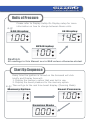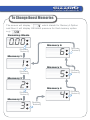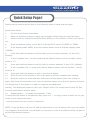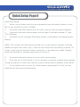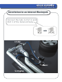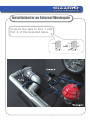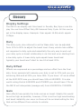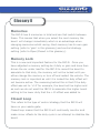
1
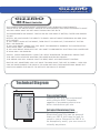
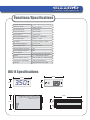
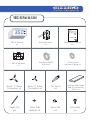
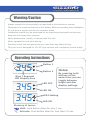
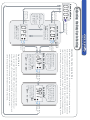
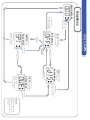
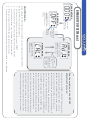
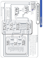
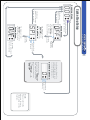
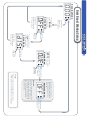
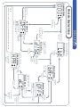
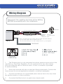
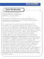
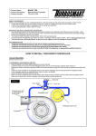
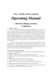
Real Performance Product By GIZZMO
Thank you for purchasing the Gizzmo
IBC-R RPM dependent Boost Controller
Boost Controller. This manual contains
operating instructions and installation
procedures that are needed for the fitting
and operation of this product
.
Instruction Manual
gizzmo
ELECTRONICS
www.gizzmoelectronics.com
gizzmo
ELECTRONICS
gizzmo
IBC-R Boost Controller
THE COMPETITION GRADE BOOST CONTROLLER WITH EVERYDAY FUNCTIONALITY.
TAKING WHAT WE KNOW FROM A DECADE OF DEVELOPMENT, AND FROM LISTENING TO WHAT
YOU END USERS WANT WE SET ABOUT PRODUCING THE IBC-R.
THE INGREDIENTS ARE SIMPLE. TAKE AN MS-IBC AND MAKE IT BETTER, FASTER AND EASIER
TO USE.
BETTER: WE HAVE ADDED THE ABILITY TO EASILY ADJUST BOOST DEPENDING ON RPM (RPM
DUTY OFFSET)
IF YOU WANT A HARD HIT OF BOOST, THEN FOR IT TO LEVEL OUT, THEN RISE AT THE TOP
END? NO PROBLEM
IF YOU HAVE BOOST CREEP THAT YOU WANT TO MINIMISE BY OPENING THE WASTEGATE AS
YOUR RPM’S RISE? NO PROBLEM
IF YOU HAVE BOOST DROP OFF THAT YOU WANT TO MINIMISE BY SHUTTING YOUR WASTEGATE
AT HIGH RPM? NO PROBLEM
FASTER: 64MHZ PROCESSOR. USING THE LATEST PROCESSOR TECHNOLOGY MEANS THAT
THIS UNIT WILL NEVER BE WANTING FOR MORE PROCESSING POWER!
THIS MEANS YOU WILL ALWAYS HAVE THE BEST, MOST ACCURATE BOOST CONTROL
EASE OF USE: SOMETIMES YOU JUST WANT TO KNOW WHAT THE UNIT IS DOING... NOW YOU
CAN! WE HAVE ENABLED THE DISPLAY TO SHOW NOT ONLY THECONVENTIONAL BOOST BUT
HAVE ALSO ADDED THE ABILITY TO SEE DUTY OR RPM DUTY OFFSET
Technical Diagram
Processing Power
Gizzmo’s IBC-R is over engineered
with a 64mhz RISC Processor
capable of processing almost one
billion instructions per min.
Extruded Aluminium Case
By utilising a rugged Extruded
Aluminium case you can be assured
that your IBC-R will keep its look for
years to come. Because the IBC-R is
so deceptively small, you can mount it
virtually anywhere.
gizzmo
ELECTRONICS
Functions/Specifications
Number of boost memories
6 with individual gain settings
Maximum boost
50psi (3.5bar)
Processing Power
64 mhz RISC
Active Over Boost
5psi to 50psi
Boost Control
Closed loop
Boost Offset RPM Range
2000rpm ~ 9000 rpm
Boost Offset Duty
-50% ~ +50%
IBC-R size
117mm * 57mm * 26mm
Operating Voltage (v)
11.8V - 21V
Operating Current
Less than 0.5A
Reverse Battery Protection
Yes
Overcharging Protection
Yes
Case Material
Anodised Extruded Aluminium
Display
3 * 7seg BLUE LED display
Pressure display options
KPA, PSI, BAR, DC, DUTY OFFSET
Wastegate Compatibility
Internal and External
Solenoid
High Performance Single
IBC-R Specifications
55mm
55mm
24mm
3.5 0
24mm
89mm
57mm
26mm
gizzmo
ELECTRONICS
IBC-R Parts List
3. 5 0
Thank you for purchasing the Gizzmo
IBC-R RPM dependent Boost Controller
Boost Controller. This manual contains
operating instructions and installation
procedures that are needed for the fitting
and operation of this product
.
ELECTRONICS.LTD
IBC-R Module
x1
1
2
3
4
5
6
7
8
IBC-R Harness
x1
Solenoid Valve
x1
Instruction Manual
x1
1mx5mm Nitrile
Tubing x1
1.2mx2.8mm
Vacuum Tubing x1
5mm ‘Y’ Piece
Connector x1
3mm ‘Y’ Piece
Connector x1
Tail 5mm
x2
Cable Tie
x8
3mm Flat
Washer x2
3mm Nut
x2
Double sided Tape
Pad For Mounting
MS-2 x1
3mm Bolt
x2
gizzmo
ELECTRONICS
Warning/Caution
Always connect the wiring exactly as described in the instruction manual.
Disconnect the negative terminal of the battery before proceeding with installation.
Do not drop or expose this unit to excessive shock.
Installation should only be performed by an experienced automotive electrician.
Keep this unit away from moisture.
Never disassemble, modify, or tamper with this unit.
Never operate this unit while driving.
Securely mount this unit away from any area that may effect driving.
This unit is only designed for 12V DC type vehicles with a negative ground supply.
Operating Instructions
3. 4 5
Button 1
Button 2
Blue 7 Segment
LED Display Area
3. 4 5
3. 4 5
LED OFF
Notes:
By pressing both
buttons at the
same time you can
toggle between
bright and dim
display settings.
LED ON
LED Flashing
LED ON
Glossary of terms:
Hold: Push Button down for over 1 sec.
Activate: Push Button down for less than 0.5 sec.
gizzmo
ELECTRONICS
Units of Pressure
e.g:
Please refer to Display SetUp On Display setup for more
information on how to change between these units.
BAR Display
LB Display
1. 0 0
1 4.5
KPA Display
100
Caution:
All readings in this Manual are in BAR unless otherwise stated.
Start Up Sequence
e.g:
Every time the ignition is turned on the Solenoid will click
briefly and Display Area will:
1. Display the memory option that was last in use.
2. Display the boost pressure for the memory option.
Then will go to the real time boost display. (Running Mode)
Memory Option
Boost Pressure
1. 0 0
Running Mode
0. 0 0
gizzmo
ELECTRONICS
To Change Boost Memories
The screen will display ‘
’ which stands for Memory1 Option
and then it will display the boost pressure for that memory option
e.g: ‘ .
’.
Running Mode
0. 0 0
Memory 6
6
【Activate
Button2】
Memory 1
【Activate
Button2】
Memory 5
【Activate
Button2】
【Activate
Button2】
Memory 2
Memory 4
4
【Activate
Button2】
Memory 3
3
【Activate
Button2】
【Activate
Button2】
gizzmo
ELECTRONICS
Quick Setup Page I
Setting up the boost must be done in the following order of boost and then gain.
Quick Boost Setup
1.
Fit Unit as per these instructions.
2.
Start car and allow engine to warm up thoroughly whilst doing the next few steps.
3.
Set the memory (using the top OR bottom button) to the memory number you want to
set.
4.
Press the bottom button on the IBC-R until the IBC-R scrolls ‘CLOSED’ or ‘OPEN’.
5.
If the display reads ‘OPEN’, press the bottom button once so that the display reads
‘CLOSED’.
6.
Press and hold both buttons until the duty cycle (a number between ‘10’ and ‘90’)
displays.
7.
If this is greater than ‘10’ press and hold the bottom button until the number comes
down to ‘10’
8.
Press and hold both buttons until the gain (a number between ‘0’ and ‘100’) displays.
9.
If this is greater than ‘0’ press and hold the bottom button until the number
comes
down to ‘0’.
10.
Press and hold both buttons to exit to the normal display
11.
Drive the car on full throttle in 3rd or 4th gear to achieve a stable boost reading.
12.
Bring the vehicle to a halt and then either turn off the ignition then turn it back on
again, OR, Press the top button once, then the bottom button once (this will put the controller
into boost level 2, then back to 1 again to read the recorded boost
setting). This displayed pressure is the new "Target" boost. Let us say that this was 12.5psi
and you would like to achieve 16psi.
13.
Repeat steps 4 – 11 replacing instruction 7 with…
7b using the top button to increase the duty cycle by 5 – 10 using a lower number as you get
closer to your desired pressure
…until the boost level you require is achieved.
NOTE: If you get duty cycle over 50 and the boost level is not increasing, then you have either
not plugged in the solenoid, not plumbed it in correctly or have a mechanical setup not able to
achieve the desired pressure.
gizzmo
ELECTRONICS
Quick Setup Page II
Quick Gain Setup
1.
When you are happy with the boost pressure press the bottom button on the
IBC-R until the IBC-R scrolls ‘CLOSED’
2.
Press and hold both buttons until the duty cycle you set previously displays.
3.
Press and hold both buttons again until the gain (a number between ‘0’ and
‘100’) displays.
4.
Press the top (to increase) OR bottom button (to decrease) the displayed gain
setting.
NOTE: This number will take some trial and error to set however typically it should
NEVER be higher than duty cycle, in fact we have found the best setting is below ‘20’.
If gain is too high the boost will either overshoot, or the maximum stable (Target)
boost will fluctuate or increase every time you drive it!
5.
Press and hold both buttons to exit to the normal display
6.
Drive the car on full throttle in 3rd or 4th gear to achieve a stable boost reading
noting the manner in which the vehicle comes on boost and the stability of the boost.
7.
If you believe there is room for improvement repeat steps 2-6 until you are
satisfied with the boost characteristics.
【Activate Both
Button1 And
Button2】
【Activate Both
Button1 And
Button2】
Use Button1/Button2
to set the Duty Cycle
Percentage. The Setting
Range is from 10%~90%
in 1% increments.
Gain Menu
Use Button1/Button2 to
set the Gain Percentage.
The Setting Range is from
0%~100% in 1% increments.
【Activate Both
Button1 And
Button2】
The display will toggle
between scrolling “
”
and the present gain
setting.
e.g: “
”<> <>“
”
Duty Cycle Menu
The display will toggle
between scrolling “
”
which stand for duty cycle
and the present duty cycle
setting.
e.g: “
”<> <>“
”
Open/Closed
【Activate Both
Button1 And
Button2】
Hold down the bottom button2 until the screen displays ‘CLO’ and then release the button.
At this point the display will scroll ‘CLOSE’ which represents the option of closed loop boost
control; at this point you can push either button to toggle to open loop should you desire
(refer to the glossary for more information on these 2 functions). Upon the display showing
your desired setting, you must push both buttons to go through to the ‘Duty’ setting screen.
Adjusting the Duty Cycle Setting
gizzmo
ELECTRONICS
【Hold down Button2
for two seconds】
Control Menu
The display will scrolling
“
”which stand for
the Closed Loop Setting
Light Off
Adjusting the Duty Cycle Setting
Running Mode
0. 0 0
【Hold down
Button1 or Button2
for two seconds】
Use either
Button1/Button2
to select
between Closed
Loop and Open
Loop Settings.
【Hold down
Button1 or Button2
for two seconds】
ope
The display will scrolling
“
”which stand for
the Open Loop Setting
This refers to the type of control the IBC-R will apply to your waste-gate.
If you select ‘open’ the IBC-R will NOT attempt to correct any fluctuations or
boost creep/drop off. If you select ‘closed’ the IBC-R will continually monitor and
make minor offsets to the duty cycle in an attempt to stabilise the boost.
(refer to the glossary for more information on these 2 functions).
【Hold down
Button1 for
two seconds】
Setup Menu
Running Mode
0. 0 0
【Hold down
Button1 or Button2
for two seconds】
Light Off
【Activate
Button1】
gizzmo
ELECTRONICS
Setup Menu
The display will scrol
“
” which stand
for Duty Cycle Offset
Setting.
【Activate
Button2】
【Activate
Button2】
The display will scrol
“
” which
stand for Spike Stop. 【Activate
Button1】
Setup Menu
SpI
【Hold down
Button1 or Button2
for two seconds】
Setup Menu
The display will scrol
“
” which stand
for Display Setting.
【Activate
Button2】
【Activate
Button2】
【Hold down
Button1 or Button2
for two seconds】
Setup Menu
The display will scrol
“
” which stand
for Over boost Setting.
【Hold down
Button1 or Button2
for two seconds】
Note:
Please refer to the
glossary for more
information on this
function.
Light Off
The Screen will display
“
” which stands for
IBC-R Calibration
OFFSET Mode
The Screen will display
“
” which stands for
Adjust Offset Duty
OFFSET Mode
gizzmo
ELECTRONICS
【Activate Both
Button1 And
Button2】
【Hold down
Button1 for
two seconds】
RPM/DUTY OFF SET Menu I
Running Mode
0. 0 0
Setup Menu
The display will scrol
“
” which stand
for Duty Cycle Offset
Setting.
CAUTIONS A:
Use either
Button1/Button2
to select
between Adjust
Offset Duty and
IBC-R Calibration Settings.
Before utilizing the offset features of the IBC-R you must calibrate the IBC-R’s RPM to
4.
3.
2.
1.
The display should now return to normal running mode and you IBC-R is now calibrated
Bring your engine to 2000RPM and push both buttons to enter
Push the bottom button once. The display should now read ‘CAL’
Push both buttons to enter. The display should now read ‘ADJUST’
Hold down the top button until the display reads ‘OFFSET’
the engine RPM. This is a simple procedure…
5.
Brief description of the OFFEST
adjustment process:
When entering the ‘OFFSET > ADJUST’ mode you will be
presented with your RPM zones from ‘2000 – 9000’ in
addition to a ‘SET’ and ‘ESC’ option. At any of the RPM
zones you can push both buttons to enter these to
adjust the offset. When you enter a zone the display will
show the offset for that zone and may be adjusted from
-50 to +50. The IBC-R will interpolate (average out)
from between zones e.g. if you set +5 at 6500RPM and
0 at 6000RPM the duty will be +2 at 6200RPM. Upon
having set your offset duty you must again press both
buttons to exit out back to the RPM zones. This process
can be repeated to make whatever adjustment you
need to do prior to saving. Having finished making your
adjustments you must press the top button to scroll up
to either ‘SAVE’ (should you wish to make your adjust-
ments permanent) or ‘ESC’ (should you wish to abort
without saving the adjustments you have just made).
【Activate
Button2】
【Activate
Button1】
【Activate Both
Button1 And
Button2】
【Activate
Button2】
【Activate
Button1】
【Activate
Button1】
900
Use Button1
or Button2
to select the
Engine RPM.
The Setting
Range is from
2000~ 9000
in 500 Steps.
200
RPM Menu
gizzmo
ELECTRONICS
RPM/DUTY OFF SET Menu II
Running Mode
0. 0 0
Light Off
【Hold down
Button1 for
two seconds】
Setup Menu
【Activate Both
Button1 And
Button2】
OFFSET Mode
【Activate Both
Button1 And
Button2】
【Activate
Button2】
【Activates Both Button1 And Button2】
SET = To Return to Running Mode
& Save the new Changes.
ESC = To Return to Running
Mode and Abort Changes.
【Activate Both Button1 And Button2】
Note:
Please refer to the glossary for more
information on this function.
CAUTIONS B:
Please note that offset will not be active until a memory
has been set. This means that until a memory has been
locked (refer to Memory Lock in glossary) the offsets will be
inactive. They can still be set and will still display on the
‘OFFSET’ display screen but will NOT be added/subtracted
from the final duty.
【Activate Both
Button1 And
Button2】
Use Button1 or
Button2 to select
the RPM/DUTY
Offset. The
Setting Range is
from -50 ~ +50
in 1% steps.
If holding down
button1 or
button2 the
display will
increment or
decrement
automatically.
Activate both
Button1 and
Button2 to go
back to the RPM
Menu after
making
altesations.
gizzmo
ELECTRONICS
【Hold down Button1
for two seconds】
Spike Stop Setup
Running Mode
0. 0 0
Setup Menu
Setup Menu
The display will scroll
“
” which
stands for Spike Stop.
【Activate Both
Button1 And
Button2】
The display will
Light Off
scroll “
”
which stands for
【Activate
Duty Cycle Off Set.
Button2】
【Hold down
Button1 or Button2
for two seconds】
【Hold down
Button1 or Button2
for two seconds】
SpI
【Activate
Button2】
Setup Menu
The display will scrol
“
” which stand
for Over boost Setting.
【Hold down
Button1 or Button2
for two seconds】
Use Button1 or Button2 to
select the Spike Stop Level.
The Setting Range is from
0~100 in increments of 1.
Spike Stop Menu
0
The display will toggle
between scrolling “
”
which stands for Spike Stop.
and the Spike Stop Value
setting.
e.g: “
”<> <>
“
”
【Activate Both
Button1 And
Button2】
Note:
Please refer to the
glossary for more
information on this
function.
Setup Menu
The display will scroll
“
” which stands
for Over boost Setting.
Light Off
【Activate
Button1】
gizzmo
ELECTRONICS
Light Off
【Activate
Button1】
Over Boost Waring Setup
Running Mode
0. 0 0
【Hold down
Button1 for
two seconds】
The display will
scroll “
”
which stands for
Duty Cycle Off Set.
Setup Menu
【Hold down
Button1 or Button2
for two seconds】
Setup Menu
The display will scroll
“
” which stands
for Display Setting.
【Hold down
Button1 or Button2
for two seconds】
【Activate Both
Button1 And
Button2】
Light Off
Note:
Use Button1 or Button2 to
select the over Boost Level.
The Setting Range is from
0~3.5 Bar .
Warning Menu
off
Caution:
The over boost pressure will be
display in the same format as
the display pressure, and if the
overboost limit is exceeded the
MS-2 will attempt to reduce
the boost level.
【Activate Both
Button1 And
Button2】
Please refer to the glossary for more
information on the functions on this page.
【Activate Both
Button1 And
Button2】
Light Off
Setup Menu
The display will scrolling
“
” which stand for
Display Setting.
Light Off
h.p a
Display Menu
Button1】
【Activate
Button1】
【Activate
Display Menu Button1】
【Activate Both
Button1 And
Button2】
The display will scrol
“
” which stand【Activate
Button2】
for Duty Cycle Offset
【Activate
Button2】
【Activate Both
Button1 And
Button2】
The Screen will display
“ ” which stands for
DUTY CYCLE
【Activate
Display Menu Button1】
The Screen will
display “
”
【Activate
Button2】
Display Menu
“H PA ” which stands for KPA.
【Activate
The Screen will display
【Activate
Button2】
【Activate Both
Button1 And
Button2】
【Activate
Button2】
Display Menu
The Screen will display
“ LB ” which stands for LB
gizzmo
ELECTRONICS
Setup Menu
The display will scrol
“
” which stand
for Duty Cycle Offset
Setting.
【Activate
Button1】
【Hold down
Button1 or Button2
for two seconds】
【Hold down
Button1 for
two seconds】
Pressure Display Setup
Running Mode
0. 0 0
【Hold down
Button1 or Button2
for two seconds】
Note:
Please refer to the glossary for more information on this function.
【Activate Both
Button1 And
Button2】
gizzmo
ELECTRONICS
Wiring Diagram
Disconnect the negative terminal of the battery
BEFORE proceeding with the installation.
Solenoid
2 Core Solenoid Cable
3 Core Cable
BLUE:
RPM Input
RED:
12V Power Supply
BLACK: Earth
Notes: The RPM input wire MUST GO TO A LOW VOLTAGE SOURCE
e.g. ECU tach output, ECU to Igniter wire etc.
This wire MUST NOT go to a high voltage source e.g. coil negative
IBC-R
PRESSURE
1
2
3
4
5
6
7
8
Blue RPM Input
Loom side
of IBC-R Plug
1.
The Pressure port is to be connected to a direct pressure source at an inlet
manifold e.g. Fuel Press Regulator. Do not connect this to any other device
such as a solenoid valve or blow off valve. A 3mm Y connector is provided
to assist plumbing.
2.
Mount the solenoid with the un-used port facing downwards. Connect the
hoses as per the correct application (actuator or external wastegate).
3.
Connect the Red wire to a good fused power source that is live only when
the ignition switch is in the on position.
4.
Connected the Black wire to a good clean chassis earth.
gizzmo
ELECTRONICS
Installation for an Internal Wastegate
Connect the tails to Port 2 and
Port 3 of the Solenoid Valve.
2
3
gizzmo
ELECTRONICS
Installation for an External Wastegate
Connect the tails to Port 1 and
Port 2 of the Solenoid Valve.
1
2
gizzmo
ELECTRONICS
Glossary
Display Settings
The IBC-R can display real time boost in Pounds, Bar, Kpa or can display the real time Offset Duty OR Solenoid Duty Cycle. All this can be
set in the display menu. Example: 1bar equals 14.5lb which equals
100kpa.
Duty
This duty cycle, also referred to as the ‘Base duty’ can be adjusted
from 10% to 90% to adjust the boost level. Every vehicle has a different response to duty cycle and essentially the only way to work out
your duty cycle vs boost relationship is via trial and error starting from
a low duty cycle. A lower duty cycle equals lower boost and
typically your boost won’t start to rise till at least 20%.
Duty Offset
Offsets are expressed as a percentage and are offset from the final
duty. As an example let’s assume your duty is set to 20% and you are
achieving 16lb and at 25% you have 18lb. If you have ‘+5’ as an offset
at the 6500 RPM zone you should have 18lb at 6500RPM. It is also
worth noting that at 6250RPM and 6750RPM you should have 17lb as
the IBC-R will interpolate (average out) from 6000RPM to 7000RPM.
Gain
Gain effects how quickly the turbo comes on boost. Ideally this would
be set as high as possible; however, if this is set too high overshooting
and boost instability can occur so there will be an ideal setting for this
that will be different from vehicle to vehicle.
gizzmo
ELECTRONICS
Glossary II
Memories
The IBC-R has 6 memories in total and can fast switch between
these. This means that when you select the next memory the
boost will change immediately which is an advantage when
changing memories whilst racing. Each memory has its own gain
setting (refer to ‘gain’ in this glossary) and control strategy
setting (refer to Open/Closed in this glossary).
Memory Lock
This is a new and important feature for the IBC-R. Once you
have adjusted a memory setting be it duty or gain and have then
driven the car under load for the IBC-R to record the boost to
associate to that duty, the memory will not be locked until you
either change the memory or turn off and restart the vehicle. The
memory lock is important as until it is locked the duty offset will
not become active. The reasoning behind this is that if the duty
offset was set to ‘+10’ for example, the boost will be higher and
as such we do not want the IBC-R to associate this higher boost
setting to the lower duty that the +10 offset was added to.
Closed Loop
This refers to the type of control strategy that the IBC-R will
have on your waste-gate.
Closed loop means that the IBC-R will continually monitor and
make minor offsets to the duty cycle in an attempt to stabilise the
boost.
gizzmo
ELECTRONICS
Glossary III
Over Boost warning
Via the menus, you can set an over boost pressure to flash the display
and attempt to drop the boost should your vehicle exceed this set
pressure limit.
Spike Stop
A unique feature of the IBC-R is ‘Spike stop’.
As with everything, wastegates take time to open and in a
situation where they are required to react quickly (flat shifting gears at
high revs, off/on throttle quickly whilst on boost at high rpm) this
sometimes results in a boost spike. Spike stop largely eliminates this
and can be adjusted from 0 to 100 with 100 being suitable for vehicles
with a large amount of boost spiking and 0 suiting cars with no spiking
issues. Ideally you want to keep this setting as low as possible because
the higher this is, the longer it will take to return to your desired boost
setting.
Solenoid Supervisor
The IBC-R constantly monitors the boost controller solenoid output
channel to ensure that there are no malfunctions and should anything
go wrong the IBC-R IMMEDIATELY displays ‘SOL’ to warn you of a fault
with your solenoid, solenoid loom or output driver. The IBC-R will also
briefly pulse the solenoid whenever the key is turned on in order to
ensure it is fully operational.
gizzmo
ELECTRONICS
About The Warranty
Gizzmo Electronics Limited
Limited Warranties Statement
Effective 1 January 2003
All Products manufactured or distributed by Gizzmo
Electronics are subject to the following Limited Express
Warranties, and no others:
For a period of one year from and after the date of
purchase of a new Gizzmo Electronics product, Gizzmo
Electronics warranties and guarantees only to the original
purchase/user that such a product will be free from defects
of material and workmanship in the manufacturing process.
Gizzmo Electronics, at its sole option, shall replace the
defective product. This express warranty shall be
inapplicable to any product not properly installed and
properly used by the purchaser/user or to any product
damaged or impaired be external forces. This is the extent
of Warranties available on this product. Gizzmo Electronics
shall have no liability whatsoever for consequential
damages following from the use of any defective product or
by reason the failure of any product. Gizzmo Electronics
specifically disclaims and disavows all other warranties,
express or implied including, without limitation, all
Warranties of fitness for a particular propose, Warranties of
Description, Warranties of Merchantability, Trade Usage or
Warranties of Trade Usage, The above warranty is valid in
New Zealand, Australia and the America’s only as Gizzmo
Electronics does not offer an international warranty outside
of these regions.