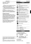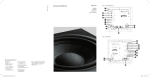
1
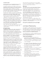
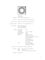
600 Series
ASW608
ASW610
Owner’s Manual
&IGURE
&IGURE
0ROCESSOR
&RONT!MPLIFIER
,INE/UTPUTS
3UBWOOFER
#ENTRE
2EAR
)NPUT
&RONT
3PEAKER/UTPUTS
2
,
,
2
30%!+%23
#ENTRE#HANNEL!MPLIFIER
)NPUT
,
2
2EAR!MPLIFIER
3PEAKER/UTPUTS
2
,
)NPUT
3PEAKER/UTPUTS
2
,
,
2
30%!+%23
3UBWOOFER
30%!+%2
&IGURE
&IGURE
0ROCESSOR
0ROCESSOR
3PEAKER/UTPUTS
3PEAKER/UTPUTS
3UBWOOFER
&RONT
2
&RONT
2EAR
,
2
2
,
2EAR
,
2
,
30%!+%23
30%!+%23
3UBWOOFER
3UBWOOFER
&IGURE
&IGURE
)NTEGRATED!MPLIFIER
)NTEGRATED!MPLIFIER
,INE/UT
3PEAKER/UTPUTS
2
3PEAKER/UTPUTS
,
2
30%!+%23
3UBWOOFER
,
30%!+%23
3UBWOOFER
Figure 7
Integrated Amplifier
Line Level Outputs
Speaker Outputs
R
L
L
R
SPEAKERS
Right Subwoofer
Left Subwoofer
Figure 8
Integrated Amplifier
Outputs
R
L
SPEAKERS
Right Subwoofer
Left Subwoofer
Figure 9
Pre-Amplifier
Line Out
L
Subwoofer
R
Power Amplifier
Line In
Speaker Outputs
R
L
L
R
SPEAKERS
Figure 10
Pre-Amplifier
Line Out
L
Subwoofer
R
Power Amplifier
Line In
Speaker Outputs
R
L
L
R
SPEAKERS
Figure 11
Left Subwoofer
Pre-Amplifier
Line Out
L
R
Power Amplifier
Line In
Speaker Outputs
R
L
L
Right Subwoofer
R
SPEAKERS
Figure 12
Left Subwoofer
Pre-Amplifier
Line Out
L
R
Power Amplifier
Line In
Speaker Outputs
R
L
L
Right Subwoofer
R
SPEAKERS
English
Owner’s manual
IMPORTANT SAFETY
INSTRUCTIONS
CAUTION
RISK OF ELECTRIC SHOCK
DO NOT OPEN
Caution:
To reduce the risk of electric shock, do not remove the
back panel. No user-serviceable parts inside. Refer
servicing to qualified personnel.
Explanation of Graphical Symbols:
The lightning flash within an equilateral
triangle is intended to alert you to the
presence of uninsulated “dangerous
voltage” within the product’s enclosure
that may be of sufficient magnitude to
constitute an electric shock to persons.
The exclamation point within an
equilateral triangle is intended to alert
you to the presence of important
operating and maintenance (servicing)
instructions in the literature
accompanying the appliance.
WARNINGS:
1. Read these instructions.
2. Keep these instructions.
3. Heed all warnings.
4. Follow all instructions.
5. Do not use this apparatus near water.
6. Clean only with dry cloth.
7. Do not block any ventilation openings. Install in
accordance with the manufacturer’s instructions.
8. Do not install near any heat sources such as
radiators, heat registers, stoves, or other
apparatus (including amplifiers) that produce heat.
9. Do not defeat the safety purpose of the polarized
or grounding-type plug. A polarized plug has two
blades with one wider than the other. A grounding
type plug has two blades and a third grounding
prong. The wide blade or the third prong are
provided for your safety. If the provided plug does
not fit into your outlet, consult an electrician for
replacement of the obsolete outlet.
10. Protect the power cord from being walked on or
pinched particularly at plugs, convenience
receptacles, and the point where they exit from
the apparatus.
2
11. Only use attachments/accessories specified by the
manufacturer.
12. Use only with the cart, stand, tripod, bracket, or
table specified by the manufacturer,
or sold with the apparatus. When a
cart is used, use caution when
moving the cart/apparatus
combination to avoid injury from
tip-over.
13. Unplug this apparatus during lightning storms or
when unused for long periods of time.
14. Refer all servicing to qualified service personnel.
Servicing is required when the apparatus has been
damaged in any way, such as power-supply cord
or plug is damaged, liquid has been spilled or
objects have fallen into the apparatus, the
apparatus has been exposed to rain or moisture,
does not operate normally, or has been dropped.
15. When replacement parts are required, be sure the
service technician has used replacement parts
specified by the manufacturer or have the same
characteristics as the original part. Unauthorised
substitutions may result in fire, electric shock or
other hazards.
16. Check that there are no cables under the carpet
that may be damaged by the spike feet. Do not
walk the product on the spike feet as this may
cause them to become detached from the cabinet
and cause damage. Take care not to impale
yourself with the spike feet.
17. For continued protection against fire hazard, use
fuses only of the correct type and rating. Mains
fuses are located inside the appliance as well as
on its back panel. Replacement of the internal
fuse should be entrusted to an authorised
operative. User-replaceable fuse types are shown
in the specification.
18. Isolation of the appliance from the power supply is
by means of removal of the power cord from the
rear of the appliance or removal of the power cord
from the wall power outlet. Either the wall outlet or
the rear of the appliance must remain freely
accessible at all times while the apparatus is in
use.
19. This product should be operated only from the
type of power source indicated by the marking
adjacent to the power cord entry. If you are not
sure of the type of power supply to your home,
consult your product dealer or local power
company.
20. Do not overload wall outlets, extension cords or
integral convenience receptacles, as this can
result in a risk of fire or electric shock.
21. Magnetic fields – The product creates a stray
static magnetic field. Do not place any object that
may be damaged by this magnetic field (eg
cathode ray tube televisions or computer
monitors, audio and video tapes and swipe cards)
within 0.5m (2 feet) of the appliance. The
appliance may cause distortion of cathode ray
tube images beyond this distance. LCD and
Plasma screens are not affected.
22. Mounting – Do not place this product on an
unstable stand, tripod, bracket or table. The
product may fall causing serious injury and serious
damage. Any mounting of the product should
follow the manufacturer’s instructions.
WARNING
TO REDUCE THE RISK OF FIRE OR
ELECTRIC SHOCK.
DO NOT EXPOSE THIS APPARATUS TO
RAIN OR MOISTURE.
Do not expose the device to rain, use it near water or
in damp or wet conditions, or place containers on it
containing liquids which might spill into any openings.
2-channel audio systems. All audio installations require
some thought in installation if they are to reach their
full performance potential and this manual will guide
you through the process.
The subwoofer requires connection to the mains
power supply, so it is important that you familiarise
yourself with the safety instructions and heed all the
warnings. Keep this manual in a safe place for future
reference.
The Subwoofer Connection and Control
Panel (Figure 1)
1. Status indicator.
2. On, Auto, Stand-by switch.
3. Line-level input volume.
4. Speaker level input volume.
5. Low-pass filter frequency.
6. Low-pass filter selection switch.
When setting up the device, make sure that the AC
outlet you are using is easily accessible. If some
trouble or malfunction occurs, immediately turn off the
power switch and disconnect the plug from the outlet.
Even when the power switch is turned off, electricity is
still flowing to the product at the minimum level. When
you are not using the device for a long time, make
sure to unplug the power cord from the wall AC outlet.
7. Bass extension switch.
Introduction
13. Mains input.
Dear customer,
Thank you for choosing B&W. Please read this manual
fully before unpacking and installing the product. It will
help you to optimise its performance. B&W maintains
a network of dedicated distributors in over
60 countries who will be able to help you should you
have any problems your dealer cannot resolve.
Environmental Information
B&W products are designed to comply with
international directives on the Restriction of
Hazardous Substances (RoHS) in electrical and
electronic equipment and the disposal of Waste
Electrical and Electronic Equipment (WEEE). The
crossed wheelie bin symbol indicates compliance and
that the products must be appropriately recycled or
processed in accordance with these directives.
Consult your local area waste disposal organisation for
guidance on how to dispose of this equipment in a
proper manner.
Carton Contents
Check in the carton for:
1 Mains cable
1 Accessory pack containing:
4 M6 spike feet
4 M6 rubber feet
4 Lock nuts (10mm across flats)
Installation
The subwoofer has been designed both for Home
Theatre installations and to augment the bass
performance of ‘full range’ speakers in
8. Equalisation switch.
9. Phase reverse switch.
10. 12V trigger input.
11. Line level input sockets (left and right).
12. Speaker level input binding posts (left and right).
14. External fuse holder.
Subwoofer Applications
The primary function of a subwoofer is to reproduce
signals from an audio-visual processor Low Frequency
Effects (LFE) channel. In addition, the processor may
be configured to divert the low bass portion from
some or all of the other channels and add it to the LFE
information. This is usually done by selecting “small”
loudspeakers in the processor set-up procedure.
In 2-channel audio applications a subwoofer is used to
extend the bass response lower than that provided by
the satellite speakers. The subwoofer low-pass filter
should be set so that the subwoofer takes over as the
output of the satellite speakers falls.
Subwoofer Positioning and Installation
The ear poorly perceives the source location of low
frequency sound so the position of subwoofers in the
listening room is generally less critical compared to
full-range speakers. However, best results are usually
obtained if the subwoofer is placed between the left
and right speakers or in the vicinity of one of them. If
two subwoofers are used, it is best to put one near
the left and one near the right speaker. Placing a
subwoofer behind the listening position, even in multichannel surround sound installations, generally results
in inferior imaging, but may be an acceptable
compromise if domestic considerations dictate.
As with all speakers, the proximity of room boundaries
affects the sound of a subwoofer. Bass volume
increases as more surfaces come into close proximity
with the speaker. Unlike full-range speakers, however,
3
the overall system balance can be corrected by
adjusting the volume level of the subwoofer. The more
boost gained from the room, the lower the volume can
be set and the less hard the subwoofer has to work;
but there is a down side. Subwoofers positioned near
corners often generate more low-frequency room
resonances, making the bass more uneven with
frequency. There is no substitute for experiment as all
rooms behave differently, so the subwoofer should be
tried in a variety of positions before a final decision is
made. A piece of music with a bass line ascending or
descending the musical scale is useful for assessing
the smoothness of the bass response. Listen for
exaggerated or quiet notes.
connections are made or broken. The subwoofer can
accept both line level signals via the RCA Phono
sockets (Item 11 in Figure 1) and speaker level signals
via the binding posts (Item 12 in Figure 1). Use the
following guide to select the appropriate connection
method for your installation:
•
using line-level inputs: Figure 3
If the subwoofer is to be used in a confined space
(e.g. built into furniture), the space must be ventilated
to allow sufficient air to circulate and cool the unit. Ask
your dealer for advice.
•
using speaker level inputs: Figure 4
The subwoofer is intended to be floor mounted only. It
is important to ensure the subwoofer stands firmly on
the floor using the spike feet supplied whenever
possible. The spike feet are designed to pierce carpet
and rest on the floor surface. Initially, screw the lock
nuts onto the spikes enough to leave the nuts floating
just above the carpet when the spikes are resting on
the floor beneath. Screw the spikes fully into the
threaded inserts in the base of the cabinet. If the
cabinet rocks when placed on the floor, unscrew the
two spikes that do not touch the floor until the cabinet
rests firmly without rocking. Finally, lock the nuts
against the cabinet. It may be more convenient to fit
and adjust the spike feet after speaker positioning has
been optimised.
If there is no carpet and you wish to avoid scratching
the floor surface, use either a protective metal disc (a
coin perhaps) between the spike and the floor or use
the supplied rubber feet. Fit the rubber feet by
screwing one into each of the holes in the underside
of the cabinet.
The grille fitted to the front of the subwoofer may be
removed if desired. Take care however not to touch
the moving parts of the drive unit as damage may
result.
Using Multiple Subwoofers
Using multiple subwoofers in a single installation can
improve performance in the following ways:
•
Maintain stereo separation to the lowest
frequencies.
•
Smooth out the effects of low frequency room
resonances.
•
Enable a higher maximum sound output.
In the case of two subwoofers used in a
2-channel audio system, stereo separation will only be
improved if each channel has its own subwoofer
located close to the appropriate satellite speaker.
Electrical Connections
Disconnect all audio system equipment from the mains
until the signal connections have been made and
checked. This avoids the risk of damage whilst
4
Application: Home Theatre
Subwoofer connected to AV Processor with separate
power amplifiers: Figure 2
Subwoofer connected to AV Processor with integrated
power amplifiers:
Note: The subwoofer is always better connected via
its line level inputs in home theatre applications.
Application: 2-channel audio
Subwoofer connected to Integrated Amplifier:
•
using line-level inputs: Figure 5
•
using speaker level inputs: Figure 6
Two Subwoofers connected to Integrated Amplifier:
•
using line-level inputs: Figure 7
•
using speaker level inputs: Figure 8
Subwoofer connected to Pre/Power Amplifier:
•
using line-level input: Figure 9
•
using speaker level inputs: Figure 10
Two Subwoofers connected to Pre/Power Amplifier:
•
using line-level inputs: Figure 11
•
using speaker level inputs: Figure 12
Before Auditioning
Before auditioning your new subwoofer installation and
fine-tuning it, double check the connections. Make
sure in particular that:
1. The phasing is correct. If the speaker level inputs
are used, ensure that the positive terminals on the
subwoofer (marked + and coloured red) are
connected to the positive output terminals on the
amplifier and that the negative terminals on the
subwoofer (marked – and coloured black) are
connected to the negative output terminals on the
amplifier. Incorrect connection can result a
confused sound with poor bass.
2. Left to right channels are not confused. Left/right
confusion can result for example in orchestral
elements appearing in the wrong place in the
stereo image, or Home Theatre sound effects not
matching the action on screen.
Switching On and Off
Subwoofers are best switched on after any other item
and switched off first. The On/Auto/Standby switch
(Item 2 in Figure 1) and Status Indicator (Item 1 in
Figure 1) operate as follows:
On: With the switch to On, the subwoofer will remain
fully active and the indicator will glow green.
Auto: With the switch set to Auto, the subwoofer will
initially become fully active and the indicator will glow
green. After about 5 minutes without an input signal,
the subwoofer will automatically enter “sleep” mode.
The indicator will glow red. When an input signal is
detected, the subwoofer will automatically become
active and the indicator will glow green. The
subwoofer will return to sleep after about 5 minutes
with no input signal.
Audio-visual processors incorporating an “automatic”
set up procedure may be “confused” by subwoofers
with an auto switch-on/sleep function. A potentially
damaging fault condition can arise. Subwoofers are
best left switched on and fully active during set up if
such a processor is used.
channel level controls in the THX® controller should be
used. In all cases the levels should be set to obtain
75dB SPL (C-weighted) at the listening position from
the controller’s internal noise test signal.
With other processors, configure the front and
surround speakers to “large” or “small” as appropriate
before setting the levels. Use the internal noise test
signal and volume controls of the processor to set the
levels of all the speakers. Only change the VOLUME
control on the subwoofer if there is not enough range
in the processor to achieve the correct levels.
Inexpensive sound level meters are readily available
from electronics stores and can be used to calibrate
the levels. Refer to your processor manual for further
details on how to set the levels.
Standby: With the switch set to Standby the
subwoofer will become active when 12V is applied to
the Trigger Input (Item 10 in Figure 1). Zero volts at the
input will return the subwoofer to sleep. The indicator
will glow green when the subwoofer is active and red
when the subwoofer is in sleep.
2-channel Audio Settings
Setting The Subwoofer Controls
Set the PHASE switch initially to 0°.
There are 7 controls to consider:
Set the VOLUME (LINE or SPEAKER) control initially to
the 9 o’clock position.
Set the LOW-PASS FILTER switch to IN.
Set the EQ switch initially to position A.
•
The VOLUME (LINE) control (Item 3 in Figure 1)
•
The VOLUME (SPEAKER) control (Item 4 in
Figure 1)
•
The LOW-PASS FREQ (frequency) control (Item 5
in Figure 1)
•
The LOW-PASS FILTER switch (Item 6 in Figure 1)
•
The BASS Extension switch (Item 7 in Figure 1)
Set the LOW-PASS FREQ control to match the -6dB
low frequency cut-off frequency of the satellite
speakers. Note: Both -3dB and -6dB figures can be
found in the specification of each B&W speaker
model. If the satellite speaker manufacturer quotes
only a -3dB frequency, the optimum setting for the
LOW-PASS FREQ control should be between 0.6 and
0.9 times that figure. The more gradual the low
frequency roll-off of the satellite speakers, the lower
the frequency should be set.
•
The EQ (equalisation) switch (Item 8 in Figure 1)
See the Fine Tuning section for more.
•
The PHASE switch (Item 9 in Figure 1)
Fine-tuning
The appropriate settings depend on the equipment
used with the subwoofer and the modes of
connection. If using more than one subwoofer, ensure
the controls on each one are set the same.
Note: The VOLUME (LINE) and VOLUME (SPEAKER)
controls only operate on their respective line and volume
inputs. An unused volume control is best set to Min.
Home Theatre Settings
Set the VOLUME (LINE or SPEAKER) control initially to
the 9 o’clock position.
Set the LOW-PASS FILTER switch to OUT.
Set the EQ switch initially to position A.
Set the PHASE switch initially to 0°.
Set the LOW-PASS FREQ (frequency) control to 140 if
the speaker level inputs are used. The setting is
irrelevant if the line level inputs are used.
See the “Fine Tuning” section for more.
The subwoofer is not a THX® licensed component, but
may be used with a THX® controller if desired. If a
THX® controller is used, ensure that the subwoofer
function is enabled. This incorporates all the filtering
and level setting required for the subwoofer in all
modes. For level calibration, the internal test noise and
Home Theatre
In home theatre systems, the subwoofer (LFE) signal is
a separate channel rather than an extension of the
signal to the satellite speakers. The LOW-PASS
FILTER is switched out (or set to maximum), because
the processor provides all the filtering for any speakers
set to “small”. However, the position of the PHASE
switch must still be assessed. Normally the phase will
be set to 0°, but if the subwoofer is positioned at a
distance significantly different from the other speakers,
or the power amplifier driving the other speakers
happens to invert the signal, the 180° position may be
preferable. Listen with the switch in both positions and
choose the one that gives the fullest sound. If there is
little difference, leave the switch at 0°.
Surround sound processors normally have a calibrated
noise signal that can be used to set the relative levels
of all the speakers, making the task somewhat more
straightforward than for 2 channel audio. However, do
not be afraid to alter the settings to your personal
preference. It is all too easy to get carried away with
the capabilities of the subwoofer, especially with some
special low-frequency effects. Often a more realistic
portrayal, and one more satisfying in the long term, is
to be had by setting the subwoofer level lower than
the standard calibration level.
5
2-channel Audio
Set the system up in the preferred position and play
some programme with a steady bass content.
The optimum settings of the PHASE switch and the
LOW-PASS FREQ control are inter-related and also
dependent on the low-frequency cut-off characteristic
of the satellite speakers. However, the settings
recommended above for the LOW PASS FREQ control
and PHASE switch have been chosen to integrate well
with most satellite speaker bass alignments.
Using the initial settings, first check the setting of the
PHASE switch. Choose the option that gives the fullest
sound. Normally the recommended option will be
optimum, but may not be in certain circumstances.
These may be that the power amplifiers feeding the
satellite speakers invert the signal or that the
subwoofer is not placed close to the satellite speakers.
Next, adjust the VOLUME (LINE or SPEAKER) of the
subwoofer relative to the satellite systems to your
liking. Use a wide variety of programme material to get
an average setting. A setting that sounds impressive
on one piece may sound overpowering on another.
Listen at a realistic volume level as the perception of
musical balance varies with sound level.
Finally, adjust the LOW-PASS FREQ control to give the
smoothest transition between the subwoofer and
satellite speakers.
All Applications
The BASS EXTENSION switch offers three options of
subwoofer bass extension. Position A gives the
greatest extension and position C gives the least
extension. Position B provides a compromise setting.
If the system is to be used at very high volume levels
or in a large listening room, restricting the bass
extension by selecting either B or C may help ensure
that the subwoofer is not asked to exceed its
performance limits. In most situations the BASS
EXTENSION switch should be left in position A.
The EQ switch alters the subwoofer bass roll-off
alignment. The bass you hear is a combination of the
subwoofer plus the effects of the room and you should
choose the position that best complements your room
and the location of the subwoofer. Position A gives a
“drier” alignment, more suited to placing the
subwoofer in a corner or compensating for a resonant
room. Position B is suited to a less resonant room
acoustic and use away from a corner.
If you get problems with uneven bass – certain bass
notes are exaggerated more than others – then you
probably have a room interface problem and it is worth
experimenting with the location of the subwoofer.
What may seem like small changes in position – 15cm
(6in) or so – can have a profound effect on the sound.
The use of multiple subwoofers can smooth the
effects of room resonances, as each subwoofer will
tend to excite resonances at different frequencies. If
you appreciably alter the relative distances from the
subwoofer(s) and satellite speakers to the listening
position, re-assess the PHASE switch setting. You
should also check the volume of the subwoofer (using
6
either the processor output levels or the VOLUME
control on the subwoofer amplifier as appropriate), but
only after setting the phase correctly.
Aftercare
The cabinet surfaces usually only require dusting. If
you wish to use an aerosol or other cleaner, remove
the grille first by gently pulling it away from the
cabinet. Spray aerosols onto the cleaning cloth, not
directly onto the product. Test a small area first, as
some cleaning products may damage some of the
surfaces. Avoid products that are abrasive, or contain
acid, alkali or anti-bacterial agents. Do not use
cleaning agents on the drive unit. The grille fabric may
be cleaned with a normal clothes brush whilst the
grille is detached from the cabinet. Avoid touching the
drive unit, as damage may result. Switch off the
subwoofer before cleaning.
Do not use the subwoofer as a table. When in use,
objects left on top of the subwoofer are liable to rattle.
In particular, avoid the risk of liquids being spilled (e.g.
from drinks or vases of flowers).
If the system is taken out of use for a long period,
disconnect the subwoofer from the mains supply.
Limited Warranty
This product has been designed and manufactured to
the highest quality standards. However, if something
does go wrong with this product, B&W Group Ltd. and
its national distributors warrant free of charge labour
(exclusion may apply) and replacement parts in any
country served by an official B&W distributor.
This limited warranty is valid for a period of five years
from the date of purchase or two years for electronics
including amplified loudspeakers.
Terms and Conditions
1
The warranty is limited to the repair of the
equipment. Neither transportation, nor any other
costs, nor any risk for removal, transportation and
installation of products is covered by this warranty.
2
This warranty is only valid for the original owner. It
is not transferable.
3
This warranty will not be applicable in cases other
than defects in materials and/or workmanship at
the time of purchase and will not be applicable:
a.
for damages caused by incorrect installation,
connection or packing,
b. for damages caused by any use other than correct
use described in the user manual, negligence,
modifications, or use of parts that are not made or
authorised by B&W,
c.
for damages caused by faulty or unsuitable
ancillary equipment,
d. for damages caused by accidents, lightning,
water, fire heat, war, public disturbances or any
other cause beyond the reasonable control of
B&W and its appointed distributors,
e.
for products whose serial number has been
altered, deleted, removed or made illegible,
f.
if repairs or modifications have been executed by
an unauthorised person.
4
This guarantee complements any national/regional
law obligations of dealers or national distributors
and does not affect your statutory rights as a
customer.
How to claim repairs under warranty
Should service be required, please follow the following
procedure:
1
2
Français
Manuel d’utilisation
IMPORTANTES
INSTRUCTIONS
CONCERNANT
LA SÉCURITÉ
If the equipment is being used in the country of
purchase, you should contact the B&W authorised
dealer from whom the equipment was purchased.
If the equipment is being used outside the country
of purchase, you should contact the B&W national
distributor in the country of residence who will
advise where the equipment can be serviced. You
can call B&W in the UK or visit our web site to get
the contact details of your local distributor.
To validate your warranty, you will need to produce the
warranty booklet completed and stamped by your
dealer on the date of purchase. Alternatively, you will
need the original sales invoice or other proof of
ownership and date of purchase.
CAUTION
RISK OF ELECTRIC SHOCK
DO NOT OPEN
Attention :
Pour réduire le risque d’électrisation, ne pas démonter
l’appareil. Il n’y a aucun élément susceptible d’être
modifié par l’utilisateur à l’intérieur. Adressez-vous
toujours à un technicien agréé.
Explication des symboles graphiques :
L’éclair dans un triangle équilatéral
indique la présence interne de tensions
électriques élevées susceptibles de
présenter des risques graves
d’électrocution.
Le point d’exclamation dans un triangle
équilatéral indique à l’utilisateur la
présence de conseils et d’informations
importantes dans le manuel d’utilisation
accompagnant l’appareil. Leur lecture
est impérative.
PRÉCAUTIONS IMPORTANTES :
1. Lisez ce manuel d’utilisation.
2. Conservez soigneusement ce manuel.
3. Respectez soigneusement tous les avertissements
de sécurité.
4. Suivez les instructions de fonctionnement.
5. Ne pas utiliser cet appareil près d’une source
humide.
6. N'utiliser qu'un chiffon doux et sec pour le
nettoyage.
7. N’obstruez aucune des ouïes de ventilation
prévues sur l’appareil. Respectez les conseils
d’installation donnés par le constructeur.
8. Cet appareil doit être placé loin de toute source
importante de chaleur, telle que cheminée,
radiateur, etc., ou même les amplificateurs de
puissance dégageant aussi beaucoup de chaleur.
9. Ne jamais démonter ou modifier une prise
d'alimentation secteur intégrant une sécurité
particulière. Une prise polarisée possède deux
lames de contact, l'une plus large que l'autre. Une
7
ASW608
Description
Active closed-box subwoofer system
Drive unit
1x ø200mm (8 in) paper/Kevlar® cone long-throw
Frequency range
-6dB at 23Hz and 25/140Hz adjustable (EQ at A)
Frequency response
Bass extension
Amplifier
±3dB 32Hz - 40/140Hz adjustable (EQ at A)
-6dB at 23Hz (position A)
-6dB at 28Hz (position B)
-6dB at 36Hz (position C)
Power output:
Rated power
consumption:
Input impedance:
Signal / noise:
Functions:
Inputs:
Low-pass filter
Dimensions
Net weight
200W
40W / 0.5W standby
33kΩ
>90dB
Volume level - line in
Volume level - speaker in
Low-pass filter frequency - line in only
Low-pass filter bypass
Bass extension
Bass roll-off alignment
Auto sense on/standby
Phase switch
Line in (RCA Phono)
Speaker in (Binding post)
12v trigger (3.5mm jack)
Active 4th-order, variable cut-off frequency
Height:
Width:
Depth:
260mm (10.2 in) not including feet
260mm (10.2 in)
330mm (13 in) including grille and controls
8.85kg (19.5 lb)
91
II11419 Issue 5
B&W Group Ltd
Dale Road
Worthing West Sussex
BN11 2BH England
T +44 (0) 1903 221800
F +44 (0) 1903 221801
[email protected]
www.bowers-wilkins.com
B&W Group (UK Sales)
T +44 1903 221 500
E [email protected]
B&W Group North America
T +1 978 664 2870
E [email protected]
B&W Group Asia Ltd
T +852 2 869 9916
E [email protected]
Kevlar is a registered trademark of DuPont.
Nautilus is a trademark of B&W Group Ltd.
Copyright © B&W Group Ltd. E&OE
Printed in China.