1
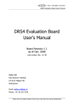
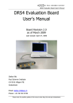
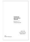
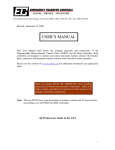
Digitizer Module SR-TR-ATCA User Manual V1.1 Rita Costa Pereira Document Configuration Company IPFN/IST- instituto de Plasmas e Fusão Nuclear Instituto Superior Técnico Av. Rovisco Pais, 1 1049-001 Lisbon Portugal Authors R. C. Pereira ([email protected]) Version VERSION 1.1 Identifier ATCA DIGITIZER – SR-TR-ATCA last update 17-01-2012 Number of Pages 128 (Including Cover) 2 Historic Date 2009/09/26 2012/1/17 Version 1.0 1.1 Description Initial Version Revised Author RitaCP RitaCP 3 Contents Document Configuration ....................................................................................... 2 Historic ................................................................................................................... 3 Contents .................................................................................................................. 4 Table List ................................................................................................................ 6 Figures List ............................................................................................................ 7 Digitizer Technical Specifications ......................................................................... 9 1 Introduction ..................................................................................................... 9 2 System Specifications ...................................................................................... 9 3 2.1 Analog Input characteristics ............................................................................ 9 2.2 Acquisition Configuration .............................................................................. 10 2.3 Trigger Source ................................................................................................. 11 2.4 Time Stamping Specifications:....................................................................... 11 2.5 Storage Capabilities ........................................................................................ 11 2.6 Processing Capabilities: .................................................................................. 12 2.7 Interface Capabilities: .................................................................................... 12 System Description ........................................................................................ 12 3.1 Digitizer Module Architecture ....................................................................... 14 3.2 Analog-to-Digital Front-End .......................................................................... 17 3.2.1 Input Channel Performance ....................................................................................... 18 3.2.1.1 TRP-250 ............................................................................................................ 19 3.2.1.2 TRP-400 ............................................................................................................ 21 3.3 System ACE CF Controller ............................................................................ 24 3.3.1 3.3.2 3.3.3 CF to configuration JTAG (CFGJTAG) setup .......................................................... 25 Test JTAG (TSTJTAG) to configuration JTAG (CFGJTAG) setup ......................... 26 MPU setup ................................................................................................................ 26 3.4 PCIe Switch ..................................................................................................... 26 3.5 External Connectors ....................................................................................... 29 3.5.1 3.5.2 Front Panel ................................................................................................................ 29 Rear Panel ................................................................................................................. 30 3.6 Intelligent Platform Management Controller (IPMC) ................................ 31 3.7 LED Indicators ................................................................................................ 32 3.7.1 Front panel LED indicators ....................................................................................... 32 3.7.1.1 PCIe LINK LEDs .............................................................................................. 32 3.7.2 Debug LED indicators............................................................................................... 33 3.8 Jumpers settings .............................................................................................. 36 4 3.8.1 3.8.2 3.8.3 SW 1 - SYSACE failsafe MODE .............................................................................. 36 SW 2 - SYSACE configuration switch ..................................................................... 36 SW5 - PEX Configuration switch ............................................................................. 37 3.9 PUSHBUTTONS (PB) .................................................................................... 38 3.10 Clock Generation ............................................................................................ 38 3.10.1 Common part ........................................................................................................ 39 3.10.1.1 33MHz oscillator ............................................................................................. 39 3.10.1.2 Global Synchronization Synthesizer ............................................................... 39 3.10.1.3 PCIe Clock Synthesizer ................................................................................... 41 3.10.1.4 CTTS clock ..................................................................................................... 41 3.10.2 Equal Blocks ........................................................................................................ 42 3.11 FPGA Architecture ......................................................................................... 42 3.11.1 3.11.2 3.11.3 3.11.4 4 Raw Mode ............................................................................................................ 44 Burst Mode ........................................................................................................... 44 Processed Mode.................................................................................................... 45 Host Data Interface ............................................................................................... 46 Digitizer Module Operation........................................................................... 47 4.1 Operating mode ............................................................................................... 48 4.2 Start Acquisition ............................................................................................. 48 4.3 Data Transfer .................................................................................................. 49 4.4 Data Format..................................................................................................... 49 5 Special Handling and Operation Considerations......................................... 50 6 TRP-400 Module Insertion at the ATCA Crate ............................................ 51 Bibliography ......................................................................................................... 52 Acronyms .............................................................................................................. 53 ANNEX A ............................................................................................................. 55 User manual for setting an acquisition on a Linux terminal .................................. 55 ANNEX B ............................................................................................................. 58 Digitizer Module Design Guidelines ......................................................................... 58 ANNEX C ............................................................................................................. 76 Schematic of the digitizer module ............................................................................. 76 5 Table List Table 2-1: Programmable acquisition rate for TRP-400 and TRP-250 digitizers. ......... 10 Table 3-1: TRP-250 module - Idle channel noise in FWHM, LSB and expected resolution of ADS5444 ADC. ........................................................................................ 21 Table 3-2: TRP-400 module - Idle channel noise in FWHM, LSB and expected resolution of ADS5474 ADC. ........................................................................................ 23 Table 3-3: System Ace Error and Status LED. ............................................................... 24 Table 3-4: Possible configurations for the digitizer PCIe switch. Defenition of the DS and US ports. .................................................................................................................. 28 Table 3-5: Front panel connectors. ................................................................................. 30 Table 3-6: Rear panel connectors. .................................................................................. 31 Table 3-7: Front panel LED indicators. .......................................................................... 32 Table 3-8: PCIE Link LEDs. The Link features are default (Hardware wired, refer to Table 3-2 ) ...................................................................................................................... 33 Table 3-9: Debug LED indicators. ................................................................................. 34 Table 3-10: SW2 - SYSACE configuration. .................................................................. 37 Table 3-11: SW5 - PEX Configuration. ......................................................................... 37 Table 3-12: Digitizer module Pushbuttons. .................................................................... 38 Table 3-13: Clock generation Integrated circuits. .......................................................... 39 Table 3-14: Currently Defined PCIe BAR Structure...................................................... 46 Table 4-1: Acquisition mode word format. .................................................................... 50 6 Figures List Figure 3-1:Block diagram of an ATCA System up to 5 digitizer modules. .................. 14 Figure 3-2: Module block diagram. ................................................................................ 15 Figure 3-3: Digitizer module Layout (TOP view). ......................................................... 16 Figure 3-4: TRP-400 Analog Block Input AC coupled. ................................................. 17 Figure 3-5: Noise histogram with inputs shorted from ADS5444 datasheet. Idle channel noise is 0.4 LSB. ............................................................................................................. 19 Figure 3-6: TRP-250 module - Noise histogram of the module channel 1 with inputs shorted to VCM. Idle channel noise is 0.4 LSB. .............................................................. 20 Figure 3-7: TRP-250 module - Noise histogram of the module channel 1 with no signal applied to the input channel, before the differential amplifier. ...................................... 20 Figure 3-8: Noise histogram with inputs shorted from ADS5474 datasheet. Idle channel noise is 1.8 LSB. ............................................................................................................. 21 Figure 3-9: TRP-400 module - Noise histogram of the module channel 1 with inputs shorted to VCM. Idle channel noise is 1.8 LSB. .............................................................. 22 Figure 3-10: TRP-400 module - Noise histogram of the module channel 1 with no signal applied to the input channel, before the differential amplifier. ...................................... 23 Figure 3-11: SYSACE CF controller Diagram Block. ................................................... 25 Figure 3-12: PCIe switching diagram block ................................................................... 27 Figure 3-13: Front Panel. ................................................................................................ 30 7 Figure 3-14: PCIe Link LED. ......................................................................................... 33 Figure 3-15: Location of the debug LED indicators at the module layout. .................... 35 Figure 3-16: SW1 – SYSACE failsafe mode jumper view. Default settings. ................ 36 Figure 3-17: SW2 - SYSACE configuration switch view. Default settings. .................. 36 Figure 3-18: SW5 - PEX Configuration switch view. Default status. US port is the ATCA CH1, PEX is hard-wired programmed. .............................................................. 37 Figure 3-19: Global clock synthesis and distribution of module references. ................. 40 Figure 3-20: Synthesis and distribution of PCIe related module clocks ........................ 41 Figure 3-21: TRP-400 acquisition and DDR2 clocks source example. .......................... 42 Figure 3-22: Block Diagram of FPGA architecture. ...................................................... 44 8 Digitizer Technical Specifications 1 Introduction The development of advanced acquisition Systems in ATCA (Advanced Telecommunications Computing Architecture) (PICMG, 2008) [1,2], has provide the means for building a new high-rate data acquisition system. Current Developer/User Manual presents the system architecture and details about acquisition capabilities. The purpose of this manual is to describe the functionality and operating modes of an 8 channel, 14(13)-bit @ 400(250) MHz, 4 GB DDR2 Memory, ATCA based Transient Recorder and Processing (TRP) module (digitizer) part of the data acquisition system. Two digitizer modules will be described: i) 14-bit @ 400 MHZ (TRP-400) and ii) 13-bit @ 150 MHZ (TRP-250). 2 System Specifications 2.1 Analog Input characteristics Eight analogue channels at: o 400 MSPS using AD5474 from TI™ (digitizer: TRP - 400); or, o 250 MSPS using AD5444 from TI™ (digitizer: TRP - 250); Resolution: o 14-bit (digitizer: TRP - 400); or, o or 13-bit (digitizer: TRP - 250); 9 AC coupled: Input Range - 0 V 1.1 V @ 50 Ω; DC coupled: Input Range 1.1V @ 50 Ω; Lemo (EPL.00.250.NTN); 2.2 Acquisition Configuration Two Blocks (block #1, block #2) of 4 channels each. Each block can be acquired simultaneously but data is retrieved from each block separately. With an acquisition rate of 400 MHz only two channels at each block can be acquired simultaneously without loosing data. 4 channels can be acquired simultaneously only at 200 MHZ; Programmable acquisition rate: VCXO / N, refer to Table 2-1. Table 2-1: Programmable acquisition rate for TRP-400 and TRP-250 digitizers. DIGITIZER TRP - 400 VCXO (MHz) 800 TRP - 250 1000 N 2 4 5 8 10 16 4 5 8 10 16 Acquisition Rate (MHz) 400 200 160 100 80 50 250 200 125 100 62.5 Free running ADCS acquisition mode (acquisition up to memory filling): o Raw data; o Segmented data (burst mode); or o Processed data; 10 XC4FX60 FPGA from XilinxTM for enhanced (and upgradeable) acquisition processing and/or control. 2.3 Trigger Source Trigger source can be given by: Software, or Hardware - Attaching a trigger signal to: o Front panel unipolar lemo (EPL.00.250.NTN): External LVTTL (3.3V) trigger. 5V tolerant; Polarity: any; o Rear panel differential Lemo (LEMO_EPL_0S_302_HLN): Compliant to RS485 standard interface (5V); 2.4 Time Stamping Specifications: Time resolution: depends on the frequency rate for example, F=400 MHz T = 2.5 ns; Over 8 days (248 x 2.5 ns) of time span; 2.5 Storage Capabilities Gbytes of data memory distributed in two blocks of four channels: 500 Mbytes per channel; 1GB of CompactFlash card memory - containing FPGA images – every time the system is powered-up the FPGA is programmed with these images; 11 2.6 Processing Capabilities: Two XC4VFX60-10FF1152C FPGAs for real time pulse processing: Pulse height analyzer (PHA); Pile-up rejection (PUR); 2.7 Interface Capabilities: ATCA based module; ATCA Fabric channel 1 (1 PCI Express – Although the board design is prepared to work with 4 PCIe links) - Compliant with PCIe rev1.1 [3]; General Purpose Input/Output (GPIO) links provided by ATCA Zone 2 connectors – ATCA Fabric channels 3 to 13 (x1 Aurora); Four GPIO - 4 Small-Form Pluggable (SFP) cages to allow gigabit links other than those provided by ATCA Zone 2 connectors; 3 System Description The data acquisition system, DAQ system, is based on the ATCATM PICMG 3.0 standar. The ATCATM base specifications define a board and architecture sharing a common backplane with interconnections based on a full mesh of serial gigabit communication links. Each slot is interconnected to all others through 1, 2 and 4 links with a maximum throughput capacity of 2 GByte/s1. Only 1 links are implemented. 1 Calculation of this bandwidth number: The transmission /reception rat is 2.5 Gbits/s per lane per direction. To support a greater degree of robustness during data transmission and reception, each byte of data transmitted is converted into a 10-bit code (via an 8b/10b encoder in the transmitter device). In other words, for every Byte of data to be transmitted, 10-bits of encoded data are actually transmitted. The result is 25% additional overhead to transmit a byte data (25% loss in transmission performance). 12 The ATCA system is composed by: ATCA shelf (sub-rack – 14 or 5 slots) ; Processor blade, a low-cost ATX motherboard mounted on an ATCA carrier module, connected to the ATCA backplane through an 16 PCIe link (3.2 GByte/s) [4]; Up to 5 digitizer modules [5]. An application programming interface (API) was developed based on the native functions (device driver) of Fedora 8 Linux-based operating system (OP) with real-time applications interface (RTAI), which supplies a layer of VxWorks® compatibility. This API can transfer data to/from the on board double data rate (DDR2) synchronous dynamic random access memory (SDRAM) or stream out processed data through the 1 PCIe link (the design is able of 4 PCIe link), as well as control all the board functionalities by using a set of specially developed commands and communication structure. The digitizer module is divided into 2 blocks (block #1, block #2) of 4 channels each. The module represents two PCIe endpoints, section 3.4. Each endpoint represents one block of the module. Where endpoint 1 is in charge of channel 1, 2, 3, 4 of the module and endpoint 2 is in charge of channel 5, 6, 7 and 8 of the module, section 3.1, Figure 3-1 and Figure 3-3. PCIe implements a dual-simplex link which implies that data is transmitted an d received simultaneously on a transmit and receive lane. The aggregate bandwidth assumes simultaneously traffic in both directions. To obtain the aggregate bandwidth numbers multiply 2.5Gbits/s by 2 (for each direction), then multiply by number of lanes, and finally divide by 10-bits per Byte (to account for the 8 to 10 bit encoding). For 1 lane 0.5GBytes/s, 2 lanes 1GBytes/s and 4 lane 2 GB/s. 13 Figure 3-1:Block diagram of an ATCA System up to 5 digitizer modules. 3.1 Digitizer Module Architecture This digitizer module has a form factor large enough to accommodate eight acquisition channels per module. The module has eight analog input channels divided in two symmetric blocks, Figure 3-1. At these speeds (400 and 250 MHZ), only fast programmable devices, especially Field Program Gate Arrays, FPGAs, can be used for data processing and transfer. The module contains two FPGAs, each controlling a memory bank of up to 2 GB and four acquisition channels and providing a gigabit communications interface, thereby reducing circuit complexity and cost by acting as a system-on-chip (SoC) device. The memory will be implemented with double data rate (DDR2) synchronous dynamic random access memory (SDRAM) providing up to 4 GB per module. Figure 3-2 represents a simplified block diagram of architecture of the digitizer module and Figure 3-3 the general view of the module. 14 Figure 3-2: Module block diagram. 15 DS8, DS7, DS10 CLK TRG CTTS Inputs DS15 DS14 J29 J30 DS2 DS6 ATCA Connectors J24 4 x SFP SW3 SW4 PCIe Switch FPGA 2GB DDR2 DC-DC 48 V -12V ATCA Power Connector FPGA 2GB DDR2 DC-DC 48 V -12V PLL Global PLL #BLK 1 ADCs #BLK 1 SW2 SW1 D1 PLL #BLK 2 ADCs #BLK 2 CF Card P1 J1 J2 J3 J4 CH3 DC CH4 DC J5 J6 J7 J8 D5D6D7D4J9J10J11 CF LED CH1 AC CH2 AC CH5 AC CH6 AC CH7 DC CH8 DC PCIe Link LEDs CLK TRG Inputs SYNC Figure 3-3: Digitizer module Layout (TOP view). 16 PB1 SW6 SW5 3.2 Analog-to-Digital Front-End Figure 3-4 shows a simplified architecture of one of the four analog AC coupled input channels. VCC5_CH Rpu2 NU Rpi_a2 CAC2 Rg2 340R 1/16W 1% Rf 2 348R 1/16W 1% Rc 49.9R 0.1uF Rpi_b2 56R2 Rpi_c2 NU 2 4 9 CM 11 THS4513RGTT VIN- VOUT+ CM_0 CM_1 VIN+ VOUT- 3 U1A VOUT_p 12 VIN_ADC_p Rf ilter2 100R Cf ilter1 2.7pF 10 VOUT_n Vin_ADC_n Rf ilter1 100R NC VCC5_CH PD 1 0R UTEST Rpu1 NU J2 5 4 3 2 EPL.00.250.NTN Rpi_a1 1 IN_p CAC1 340R 1/16W 1% Vp 0R Rpi_b1 56R2 Rpi_c1 NU Rf 1 348R 1/16W 1% 0.1uF Rg1 D1 BZX84C5V1/SOT D2 BZX84C5V1/SOT Figure 3-4: TRP-400 Analog Block Input AC coupled. This THS4513 amplifier circuit is designed for minimum gain of 0dB (THS 4513 provides up to 10dB of gain) with a low pass-filter (limiting the bandwidth to 150MHz for 400 MHz ADCs and 100 MHz for 250 MHZ ADCs). This circuit converts the single-ended AC coupled input to differential and sets the proper input common-mode voltage of the ADCs. Figure 3-4 presents the circuit for the ADS5454 (400 MHz), the 100 ohms resistors and 2.7 pF capacitor between the THS4513 outputs and ADS5474 inputs along with the input capacitance of the ADS5474 limit the bandwidth of the signal to 150 MHz (–3 dB). 17 The conditioning circuit also presents a attenuator (composed by Rpi_a, Rpi_b, Rpi_c) used to adjust signal level while controlling impedance mismatch and isolating circuit stages. Offset can be software programmable although not used (and not tested). The channels can also be DC coupled where the CAC capacitors are replaced by two 0 resistors and two RPU resistors were added to avoid violating the input common-mode voltage range (VICR) of the op amp, as the source and the input termination resistor are referenced to ground. There are two drawbacks for this configuration: (i) It requires additional current from the power supply; (ii) Increases the noise gain of the circuit. In order to minimize the noise of the DC coupling circuit, the power reference of 5 V ( VCC5_CH) next to the RPU resistor was filtered with a 0.1 uF capacitor and a ferrite bead. This circuit allowed filtering the high-frequency electronic noise. 3.2.1 Input Channel Performance From the ADC datasheets the noise histogram with inputs shorted (inputs tied to common-mode) gives a RMS idle channel noise. This figure of merit act as an ease way to understand the resolution of the described channel input architecture. The ADC output should be zero when at its input no signal is applied. The idle channel noise quantifies this leakage from zero. 18 3.2.1.1 TRP-250 Figure 3-5: Noise histogram with inputs shorted from ADS5444 datasheet. Idle channel noise is 0.4 LSB. Looking at Figure 3-5 , at Full Width Half Maximum (FWHM) there is 1 bin that it is equivalent of an idle channel of 0.4 LSB. This same study was performed for all module channels. Figure 3-6 presents TRP250 channel 1. In order to understand if the signal conditioning also introduces noise to the input channel, a similar test was performed, adding the differential amplifier to the test and connected the input to ground, this study is showed at Figure 3-7. 19 Inputs Shorted to VCM FWHM = 1 Bin 0.4 LSB Figure 3-6: TRP-250 module - Noise histogram of the module channel 1 with inputs shorted to VCM. Idle channel noise is 0.4 LSB. No input at differential amplifier FWHM = 3 Bin 1.2 LSB Figure 3-7: TRP-250 module - Noise histogram of the module channel 1 with no signal applied to the input channel, before the differential amplifier. 20 The idle channel noise in FWHM, LSB as well as the expected resolution of the module input channels are presented at Table 3-1. Table 3-1: TRP-250 module - Idle channel noise in FWHM, LSB and expected resolution of ADS5444 ADC. Idle channel noise FWHM LSB Resolution ADS5444 - Figure 3-5 1 0.4 12.6 -bit CH 1 – ADS5444 - Figure 3-6 1 0.4 12.6 -bit CH 1 – Diff Amplifier - Figure 3-7 3 1.2 11.8 -bit 3.2.1.2 TRP-400 FWHM = 4 Bin 1.8 LSB Figure 3-8: Noise histogram with inputs shorted from ADS5474 datasheet. Idle channel noise is 1.8 LSB. 21 Looking at Figure 3-8 at FWHM there are 4 bins this is equivalent of an idle channel of 1.8 LSB. This same study was performed for all module channels. Figure 3.9 presents TRP400 channel 1. In order to understand if the signal conditioning also introduces noise to the input channel, a similar test was performed, adding the differential amplifier to the test and connected the input to ground, this study is showed at Figure 3-10. Inputs Shorted to VCM FWHM = 4 Bin 1.8 LSB Figure 3-9: TRP-400 module - Noise histogram of the module channel 1 with inputs shorted to VCM. Idle channel noise is 1.8 LSB. 22 No input at differential amplifier FWHM = 7 Bin 2.8 LSB Figure 3-10: TRP-400 module - Noise histogram of the module channel 1 with no signal applied to the input channel, before the differential amplifier. The idle channel noise in FWHM, LSB as well as the expected resolution of the module input chanels are presented at Table 3-2. Table 3-2: TRP-400 module - Idle channel noise in FWHM, LSB and expected resolution of ADS5474 ADC. Idle channel noise FWHM LSB Resolution ADS5474 - Figure 3-5 4 1.8 12.2-bit CH 1 – ADS5474 - Figure 3-6 4 1.8 12.2 -bit CH 1 – Diff Amplifier - Figure 3-7 7 2.8 11.2 -bit 23 3.3 System ACE CF Controller The Xilinx System ACE (SYSACE) CompactFlash (CF) configuration controller allows a Type I CF card inserted on the CF socket, P1, present on the front panel, Figure 3-3 and Figure 3-13, to program the FPGA through the JTAG port. The System ACE controller supports up to eight configuration images on a single CF card. The configuration address switch allows the user to choose which of the eight configuration images to use, see section 3.8.2. SYSACE error and status double LED indicates the operational state of the SYSACE controller - refer to Table 3-3. Every time a CF card is inserted into the SYSACE socket, a configuration operation is initiated. Pressing the SYSACE reset button re-programs the FPGAs (because of the PCIe core, everytime the FPGA is reprogrammed the system must also restarted). Table 3-3: System Ace Error and Status LED. LED LED STATUS System ACE Status Blinking Red ERROR No Compact Flash card is present Solid Red ERROR Error condition during configuration Blinking Green OK Configuration operation is ongoing Solid Green OK Successful FPGA program download The board also features a SYSACE failsafe mode, see section 3.8.1. In this mode, if the SYSACE Controller detects a failed configuration attempt, it automatically reboots back to a redefined configuration image. This only occurs if the IPMC is onboard otherwise this feature is disabled. 24 3.3.1 CF to configuration JTAG (CFGJTAG) setup The SYSACE CF controller is the primary mean of configuring the two FPGAs (XC4VFX-11FF1152C) present on the digitizer module through the JTAG (Joint Test Action Group) interface, figure 3.5. During configuration, the SYSACE has full control of the JTAG signals. Virtex-4 FPGA is configured by loading application-specific configuration data (the bitstream file) into internal memory. Because Xilinx FPGA internal memory is volatile, it must be configured each time it is powered-up. The bitstream is loaded through special configuration pin and configuration mode. In the digitizer the bitstream is loaded through the JTAG interface (JTAG/Boundary-scan configuration mode). No system reset is needed. 3.3V SYSTEM ACE CONTROLLER FPGA1 TCK TMS TDI TDO CFG_TCK CFG_TMS CFG_TDI CFG_TDO TCK TMS TDI TDO CFG_PROG CFG_INIT PROG INIT CP INTERFACE (CFGJTAG INTERFACE) CONFIGURATION JTAG INTERFACE 2.5V MPU CFGJTAG INTERFACE PC4_TCK PC4_TMS PC4_TDI PC4_TDO MPU INTERFACE TSTJTAG INTERFACE TEST JTAG INTERFACE (TSTJTAG INTERFACE) PARALLEL CABLE IV (PC4) BUFFER 3.3V/2.5V SYSTEM ACE DIAGRAM BLOCK FPGA2 (CP) PROG INIT CFGJTAG INTERFACE 2.5V COMPACT FLASH TCK TMS TDI TDO DRW 02 13-12-2007:RCP Figure 3-11: SYSACE CF controller Diagram Block. 25 3.3.2 Test JTAG (TSTJTAG) to configuration JTAG (CFGJTAG) setup When no CF is inserted the test JTAG (TSTJTAG) to configuration JTAG (CFGJTAG) setup can be used. Using this setup the 2 FPGAs can be configured via JTAG from a JTAG compliant tool. After downloading the FPGAs programs the system must be resetted. 3.3.3 MPU setup SYSACE is connected to the FPGAs through the JTAG chain, for configuration, and through MPU port of SYSACE for allowing the FPGA of block #1 to control SYSACE and access the CF (not implemented). The ability to communicate with CF through MPU port allows the user to perform many operations, such as being able to switch the programming or in-system program new bitstreams or other files into the CF card. 3.4 PCIe Switch ExpressLaneTM PEX 8516 device [7] offers PCI Express switching capability, enabling users to add scalable, high-bandwidth, non-blocking interconnection to a wide variety of applications. This device has a flexible port width configuration and is used as a fan-out application. The upstream (US) and downstream (DS) ports are all configured as x1 although the board design is compliant with x4. There is the possibility of US port (connected to ATCA channels) be chosen from two different ATCA channels (this choice is settled by hardware strapping, dependent on were the controller is placed at the crate) and the two DS ports are connected to each block FPGA PCIe endpoint as illustrated in Figure 3-12. 26 x4 Dow x4 ATCA Zone 2 Connectors x4 nstre am p Upstream port x4 BLK1 FPGA PCIe endpoint o rt PEX8516 x4 Upstream port D tream owns p o rt x4 DRW 05 11-06-2008:RCP Blk2 FPGA PCIe endpoint Figure 3-12: PCIe switching diagram block This switch doesn’t allow an US port with spread spectrum clocking (SSC) and a downstream port with constant frequency clock (internal oscillator). Consequently the 100 MHz PCIe reference must be supplied by the root complex (controller module). Virtex-4 PCIe endpoint must be synchronously clocked to the root complex and the clock input must be 250 MHz. The 100 MHz PCIe reference must be multiplied to 250 MHZ while at the same time remaining compliant to the jitter specifications required by the Virtex-4 Multigigabit Transceivers (MGTs). To cope with this a jitter attenuator and clock distributor was used to distribute the 100 MHz PEX clock and generate and distribute the two 250 MHz PCIe endpoint clocks. The PCIe switch can be configured by hardware switches (or hardware wired) or by an EEPROM (Electrically Erasable Programmable Read Only Memory) memory. The following configurations showed at Table 2-1 are allowed by programming properly the EEPROM. The hardware wired configuration is the first option of the Table 3-4. 27 Table 3-4: Possible configurations for the digitizer PCIe switch. Defenition of the DS and US ports. Nº of PCIe US Port DS Port This configuration allows up to2 Ports 4 Notes: 4 4 4 4 3 digitizer modules (default – hardware wired) 3 8 4 4 5 digitizer modules (EEPROM) 4 8 4 2 2 3 digitizer modules (EEPROM) 4 8 2 4 2 3 digitizer modules (EEPROM) 4 8 2 2 4 3 digitizer modules (EEPROM) 2 This configuration plus the controller’s PEX configuration (de-select one of the PCIe switches of the controller) will allow up to 3 or 5 digitizer modules. If the Controller will remain with the 3 PCIe switches then only 2 digitizer modules will be possible. 28 3.5 External Connectors 3.5.1 Front Panel 29 Figure 3-13: Front Panel. All the front panel connectors are presented at Table 3-5, Figure 3-13. Table 3-5: Front panel connectors. Con. Label Mechanical Electrical specifications Polarity LEMO 00 type .1.1V @ 50 (DC ) -- EPL.00.250.NTN 0 – 1.1V @ 50 (AC ) EPL.00.250.NTN LVTTL (3.3 V – supports 5V) Specifications J1..J8 J9 CH1..CH8 CLOCK Any From 1 to 125MHz J10 START EPL.00.250.NTN LVTTL (3.3 V – supports 5V) Any J11 SYNC EPL.00.250.NTN LVTTL (3.3 V – supports 5V) Not used (NU) P1 Compact CF socket Type I CF card --- Flash 3.5.2 Rear Panel Control Trigger and Timing System compliant to JET (CTTS) is composed by two signals: CTTS Clock and CTTS trigger, Table 3-6. The small form factor (SFP) host connector and EMI cages can be used to implement a high-speed serial protocol over fibre. These connectors support data rates up to 2.5 Gbps and such as: PCIe, AURORA, Infiniband, Gigabit Ethernet or Fibre Channel (NU). These connectors are for General Purpose I/O (GPIO) use, Table 3-6. 30 Table 3-6: Rear panel connectors. Con. Label Mechanical Electrical specifications Notes NU Specifications J30 J29 CTTS LEMO 0S type Compliant with RS485 Clock EPL.0S.302.HLN standard interface TRG EPL.0S.302.HLN Compliant with RS485 NU standard interface J19,20 GPIO SFP & EMI high-speed serial protocol PCIe Cages over fibre can be used for interface Block #1 several gigabit interfaces up tested to 2.5 Gbps NU J21,22 GPIO SFP & EMI high-speed serial protocol PCIe Cages over fibre can be used for interface Block #2 several gigabit interfaces up tested to 2.5 Gbps NU 3.6 Intelligent Platform Management Controller (IPMC) The module has a vertical receptacle 38 way adaptor (J24) to connect an IPMC, Figure 3-1. This IPMC is a microcontroller module that should reside in the ATCA module aiming to control and monitor the operations of its host. This IPMC should be responsible for the communication between shelf manager3 and the several components in the shelf. IPMC plays the role of relaying data to and from shelf manager [8]. 3 Shelf manager: Is the command center of the shelf. It assures a proper operation of boards and rest of the shelf. It monitors the system’s health, retrieves inventory information and controls the performances of the Field Replaceable units (as setting fan level). 31 Up to now there is no IPMC on the acquisition module. As soon as this feature is implemented, the SYSACE failsafe mode will be enabled, see section 3.3. 3.7 LED Indicators 3.7.1 Front panel LED indicators Front panel LED indicators are presented at Table 3-7 and can be seen at Figure 3-13. These LEDs are divided into 3 different information groups: i) CF being inserted and the 2 FPGAs being properly programmed; ii) Indicates how the 3 PCIe links and respective lanes are working properly; and iii) ATCA mandatory LEDs that informs if the module is properly inserted and detected and provide basic feedback about failures and out-of-service states. Table 3-7: Front panel LED indicators. LED Label D1 CF Note SYSACE error and status LED, refer to Table 3-3 D4...D7 PCIe LINK Indicates all working lanes at each PCIe Link, refer to Table 3-8 D2 (Blue LED) H/P ATCA specification: Hot-Swap (mandatory) D3 (Amber) OOS ATCA specification: Out-Of-Service (mandatory) 3.7.1.1 PCIe LINK LEDs The D4, D5, D6 and D7 are composed by 4 LEDs each. The configuration is presented at Figure 3-14 (looking to the front panel). 32 Figure 3-14: PCIe Link LED. Looking at the front panel the LED order is from the left to the right (or from up to down if the module is in vertical position): D5, D6, D7, D4, Figure 3-13. Table 3-8: PCIE Link LEDs. The Link features are default (Hardware wired, refer to Table 3-4 ) LED PCIE Link D4 PEX to ATCA CH 1 (default link) D5 Block #2: FPGA to PEX (1 PCIe link) D6 D7 PEX to ATCA CH 12 (Not Used) Block #1: FPGA to PEX (1 PCIe link) LED order D4_1 : Lane3 (ON) D4_2 : Lane2 (ON) D4_3 : Lane1 (ON) D4_4 : Lane0 (ON) D5_1 : Lane3 (OFF) D5_2: Lane2 (OFF) D5_3: Lane1 (OFF) D5_4: Lane0 (ON) D6_1 : Lane3 (OFF) D6_2: Lane2 (OFF) D6_3: Lane1 (OFF) D6_4: Lane0 (OFF) D7_1 : Lane3 (OFF) D7_2: Lane2 (OFF) D7_3: Lane1 (OFF) D7_4: Lane0 (ON) 3.7.2 Debug LED indicators 33 Debug LED indicators are presented at Table 3-9 and its location at the module layout is presented at Figure 3-15. These LEDs are divided into 4 different information groups: i) FPGA Status; ii) DDR2 status; iii) PLL status; and iv) Not defined, can be used for future debugging functions for future applications of this ATCA system. Table 3-9: Debug LED indicators. LED DS8 DS7 Ds15 DS6 Ds14 DS2 Status Note Red: ERROR - FPGA programming; Block #1 FPGA DONE Off : FPGA programmed OK; Red: ERROR - FPGA programming; Block #2 FPGA DONE Off : FPGA programmed OK; Green: initialization OK; DDR2 Block #1 Red: ERROR (not initialized); Initialization Status Green: initialization OK; DDR2 Block #2 Red: ERROR (not initialized); Initialization Status Green: initialization OK; PLL Block #1 Red: ERROR (not initialized); Initialization Status Green: initialization OK; PLL Block #2 Red: ERROR (not initialized); Initialization Status DS1, DS3, DS4, DS5, DS11, DS10, DS9, DS12, Not Used DS13 34 Figure 3-15: Location of the debug LED indicators at the module layout. 35 3.8 Jumpers settings The jumper location is showed at Figure 3-3. 3.8.1 SW 1 - SYSACE failsafe MODE SW1 on 1 SYSACE ERRLED SYSACE RESET FPGA PROGRAM SYSACE ERRLED Figure 3-16: SW1 – SYSACE failsafe mode jumper view. Default settings. In order to System ACE failsafe mode detects a failed configuration attempt the SW1 must be on. Without IPMC this feature is disabled. Not usedf. 3.8.2 SW 2 - SYSACE configuration switch SW2 CFGMODE CFGADDR2 GND CFGADDR1 CFGADDR0 1 on Figure 3-17: SW2 - SYSACE configuration switch view. Default settings. 36 Table 3-10: SW2 - SYSACE configuration. SW2 Status Note: refer to Figure 3-17 ON – 0 (GND) Inhibits the SYSACE from configuring after reset or power up and can only be commanded by the MPU control. CFGMODE OFF - 1 Allows SYSACE to configure mode behavior after reset or power up, default. CFGADDR[2..0] 0000 This allows up to 8 different ace files at the CF, default. 3.8.3 SW5 - PEX Configuration switch SW5 1 on UP_PORT0 GND EEPRN Figure 3-18: SW5 - PEX Configuration switch view. Default status. US port is the ATCA CH1, PEX is hard-wired programmed. Table 3-11: SW5 - PEX Configuration. SW5 Status Note: refer to Figure 3-18 ON – 0 (GND) US port is CH1, default OFF - 1 US port is CH2 UP_PORT0 EEPRN ON – 0 (GND) PEX is programmed by the EEPROM, Serial EEPROM present OFF - 1 PEX is Hard-wired programmed, default, Serial EEPROM not present 37 3.9 PUSHBUTTONS (PB) Table 3-12: Digitizer module Pushbuttons. PB Function Notes: Once the pushbutton, PB, pressed: PB1 PEX_RST PEX is resetted without rebooting the system. SW4 SYSACE_RST SYSACE CF controller is resetted without rebooting system. SW3 PPC_RST PowerPC inside each FPGA is resetted without rebooting system. This feature isn’t used and this signal can be used for another operation to be defined (IPMC not implemented). SW6 IPMC_RST IPMC is resetted without rebooting system. SW7 HANDLE_SWITCH IPMC informs the shelf manager that a module has been inserted to the system (Not implemented). Table 3-12 shows all the PB present at the digitizer module, each name and function. 3.10 Clock Generation The clock generation section of the digitizer module can be divided into three parts, a common one and the two equal blocks #1 and #2 , Table 3-13. The common part is provided by several external clocks, oscillators and two phase locked loops, PLLs, (ICS874003-02 from IDT® and AD9510 from analog devices®). Each of the two equal blocks is provided by one PLL (AD9510) with external VCXO from Silicon Laboratories® (1GHz / 800 MHz, 3.3v LVDS, +-20ppm, 14 peak-to-peak jitter, 2ps rms jitter), followed by clock distribution system. The common AD9510 operate as the other two, but with 1 GHz external VCXO, also from Silicon Laboratories®. AD9510 is 38 partitioned into two parts, the PLL section (for synchronization purposes) and distribution section, this last section is in use. Table 3-13: Clock generation Integrated circuits. IC AD9510 Quant. 3 Supplier Analog Devices® ICS874003-002 1 IDT SG-636 1 Common 33 MHz (oscilattor) EG-2101CA 1 Common 125 MHz (oscilattor) Si550 (VCXO) 1 Epson Toyocom® Epson Toyocom® Silicon Lab. Common 1 GHz (VCXO) SI550 (VCXO) 2 Silicon Lab. Block 3.10.1 Common part 3.10.1.1 33MHz oscillator Distribuição Common, Block Common Frequency PLL PLL TRP-250: 1 GHz TRP-400: 800 MHz Provides a single-ended low-frequency clock necessary to the SYSACE and also distributed to both FPGAs to allow a low frequency to cope with serial peripheral interface (SPI) frequencies. The three AD9510 PLLs are programmed through SPI. This clock is generated by a local Oscillator SG-636 from Epson Toyocom®. 3.10.1.2 Global Synchronization Synthesizer The global synchronization Synthesizer is responsible for generating most important module clock references maintaining phase lock with source references. It 39 uses a clock distribution with integrated PLL chip, AD9510 from Analog Devices ® and a VCXO from Silicon Laboratories®, Figure 3-19. The PLL can use the following selectable clock reference sources (hardware coded): 1. Local 125 MHz LVPECL low jitter SAW oscillator (25 ps peak-to-peak jitter, +-100ppm), directly connected to the common PLL reference clock. Use EG2101 from Epson® (Default). 2. External unipolar LEMO (J30). Can have 1 to 10 MHz. It is compatible with JET CTTS_CLK. 3. Block #1 FPGA LVPECL 2.5V IO standard output. This is sourced by FPGA infrastructure. 1 GHz VCXO CLK FPGA_SR_CLK Local 125 MHz CLK EXT_REFCLK REFCLK ADS9510 Local 100 MHz CLK BLK1 REFCLK 125 MHz BLK2 REFCLK 125 MHz UNUSED BLK1 CLKMGT2 250 MHz BLK1 CLKMGT10 250 MHz BLK2 CLKMGT2 250 MHz BLK2 CLKMGT10 250 MHz (LVPECL) (LVDS) Figure 3-19: Global clock synthesis and distribution of module references. The Global Synchronization Synthesizer generates the following clock references: 1. BLKx REFCLK clock reference (125 MHz) for each acquisition block. 2. Local Reference for PCIe clocking (100 MHz). This is used when no System Controller is present. 3. Four 250 MHz clocks, divided into 2 clocks for each module block directly connected to the FPGA MGTs dedicated clocks. 40 3.10.1.3 PCIe Clock Synthesizer When the controller module is present it can supply a reference clock (through the root complex) on the ATCA Zone-2 (CLK3B, Annex C) for module PEX and PCIe endpoints (Virtex-4 firmware). The references are synthesized by ICS874003-02 from IDT, Figure 3-20. This is the default operation mode. When no ATCA controller is present the reference is supplied by the Global Synchronisation Synthesizer. (LVPECL) SSC 100 MHz CLK Local 100 MHz CLK REFCLK ICS874003 BLK1 PCIe 250 MHz CLK BLK2 PCIe 250 MHz CLK (LVDS) PEX 100 MHz CLK Figure 3-20: Synthesis and distribution of PCIe related module clocks 3.10.1.4 CTTS clock CTTS clock is supplied by differential LEMO through rs485 interface and is connected to each FPGA for synchronization purpose. The acquisition clock must be synchronized with the system clock (for example in JET, all acquisition channels must be synchronized with the JET’s clock - 1MHz). If the acquisition system has only one acquisition module, this signal is used as the internal clock (clk_int) to synchronize the system. If more than one acquisition module is used, than a master module must be settled. This settlement is hardware coded by means of a jumper (JMP1) or can be done by the host using the IPMC (not implemented). Once the master is settled, the block#1 FPGA knows that must send the CTTS clock through the DS91C176 M-LVDS transceiver to the crate backplane by setting the transmit enable of the transceiver and simultaneously receive it to the block#1 FPGA 41 (CTTS backplane clock - supplied by a zone 2 ATCA connector connected to each FPGA – Synchronization purpose). All the slave modules will only receive the clock from the backplane (the transmit enable is always off). All system modules will use the CTTS backplane clock as clk_int and all system acquisition channels will be synchronous with clk_int. 3.10.2 Equal Blocks BLOCK #1,#2 PLL (AD9510) is in charge of respectively 4 acquisition clocks and the 2 DDR2 controller clocks, Figure 3-21 presents an example of a TRP-400 digitizer module. The clock reference is given by the global Synchronization Synthesizer, section 3.10.1.2. The acquisition clock can be chosen from 8 different values, refer to Table 2-1. 800 MHz VCXO CLK 50 MHz to 400 MHz ADC A CLK 50MHz to 400 MHz ADC B CLK (LVPECL) 50MHz to 400 MHz ADC C CLK 50 MHz to 400 MHz ADC B CLK BLK # REFCLK 125 MHz REFCLK UNUSED 200 MHz DDR2 operating CLK ADS9510 REF CLK of 200 MHz for the IDELAY of DDR2 controller UNUSED (LVDS) Figure 3-21: TRP-400 acquisition and DDR2 clocks source example. 3.11 FPGA Architecture FPGA is directly connected to the free-running ADC channels acting as: Temporary data buffer; Real-time event manager; 42 Time stamping and Performing some high speed algorithms like digital level trigger detection, PHA with pile-up rejection (PUR). Each acquisition block of four input channels has its own control and resources. The firmware allows a continuous acquisition mode where data is continuously stored from an initial trigger until memory filling or acquisition disabled by software. The stored data can be raw, segmented (burst mode) or processed. Data retrieval is executed in post-shot (offline) either raw, segmented or processed data, Figure 3-22. 43 Figure 3-22: Block Diagram of FPGA architecture. 3.11.1 Raw Mode At raw data mode all acquired data is stored in the DDR2 memory. The module data transfer bandwidth is different for each version: TRP250 and TRP400: TRP-250 One sample 13-bit 2bytes; One channel 2 bytes @250 MHz = 500 MB/s; 1 digitizer module 8 channels = 4 GB/s Local memory: The module has 4 GB of local memory. At free-running mode the module memory will take 1s to fill it up. Real-time transfer: it isn’t supported to this acquisition mode. TRP-400 One sample 14-bit 2bytes; One channel 2 bytes @ 400 MHz = 800 MB/s; 1 digitizer module 8 channels =16 GB/s Local memory: 0.5 s of raw acquisiton. Real-time transfer: it isn’t supported to this acquisition mode. 3.11.2 Burst Mode During burst mode, for each event detection, any new incoming event is neglected, that is, the system does not present dead time. Every time an event occurs, a user defined number of samples (PWIDTH) are stored with an associated timestamp, 44 setting the beginning of each pulse event for time reconstruction, thus allowing timeresolved spectroscopy. After storing the triggered event on a temporary buffer, the system waits for another trigger. Meanwhile, if pile-up occurs, then it has to be resolved off-line. The system allows the selection of two trigger modes: by level and by edge. In the former, a voltage level comparison is performed between successive samples and a user defined threshold value; while on the latter, a linear regression is done to the rising edge of the event. If the difference between consecutive samples is higher than a slope value, an event has occurred. This type of triggering is more accurate in respect to the level one, since it is more insensitive to time jitter. For this acquisition mode the read bandwidth doesn’t depend on the sampling rate but instead on the event counting rate: TRP-250 & TRP-400 Segment width (PWIDTH) = 512 samples per event; 512 2 bytes (~2 us/1.28 us) = 1024 bytes (1KB) per channel; 4 GB /1kB = 4 Mevents/s. If the counting rate is of 1 Mevent/s the memory will be filled up within 4s. If the PWIDTH = 256 the filling time will increase to 8 s. 1 PCIe link 2.5 Gb/s for 4 channels for one direction the mdlue can attain 200 MB/s. If in the future the module will work with 4 PCIe link this value will increase to 800 MB/s. 3.11.3 Processed Mode At processed data mode, per each detected event, 48 bytes are stored, where 8 bytes have the timestamp and channel information and the lasting 40 bytes have the pulse energy information. For processing data, PHA and PUR were applied to each detected 45 event and the final data gathered in a word of 64-bits with the information of pulse energy, related channel and time of pulse occurrence. For this acquisition mode the read bandwidth doesn’t depend on the sampling rate but instead on the event counting rate: TRP-250 & TRP-400 Word length = 64 bytes per event per channel; 512 2 bytes (~2 us/1.28 us) = 1024 bytes (1KB) per channel; 4 GB /1kB = 4 Mevents/s. If the counting rate is of 1 Mevent/s the memory will be filled up within 4s. If the PWIDTH = 256 the filling time will increase to 8 s. 1 PCIe link 2.5 Gb/s for 4 channels for one direction the module can attain 200 MB/s. If in the future the module will work with 4 PCIe link this value will increase to 800 MB/s. 3.11.4 Host Data Interface The TRP-400 module is compliant with PCI-Express V1.0 (PCISIG, 2008) for communication protocol with the crate host controller. Table 3-14 presents the currently defined Base Address Registers (BAR) for PCIe. Table 3-14: Currently Defined PCIe BAR Structure. BAR BAR0 BAR1 BAR2 BAR3 BAR4 BAR5 Enabled Type YES4 Mem YES Mem NO --NO --NO --NO --- 4 Value 0xFFF00008 0xFFFFFF88 --------- Size(kB) 1000 0,128 --------- Add_64bit NO NO --------- While BAR0 is enabled and has 1Mbyte range it will NOT BE DECODED by V1.0 of Firmware. 46 There are a few important issues that developer must be aware for current firmware version: a) BAR0 although is defined it will not respond and no access to this zone should be made. b) No Long Addressing (64-bit) is supported. (IMPORTANT). c) Module supports only MSI (Message Signalling Interface). d) Data Retrieval from module local memory must be performed using direct memory access from module to Host and the use of MSI to manage the transfer. e) Access to outside specified register and memory zones may lead to unspecified behaviour. f) The accesses to the module by the host can be divided into three categories: 1. Commands; 2. Configuration and 3. Data Retrieval. The behavior of digitizer module as a sequence of the interaction between the board (firmware) and the host (driver) is presented at Annex B. 4 Digitizer Module Operation The user’s first action is to configure the right endpoint (module’s block), section 3. Where block #1 (first PCIe endpoint, section 3.4) is configured by addressing the logical slot number of the crate, correspondent to the place where it is inserted, slot n and block #2 (second PCIe endpoint) is configured by choosing slot n+12, Annex A. From the point of view of the Operating System (OS), each address points to a different device using the same Linux Device driver, section 3.1. If more than one module is to be used, for each module two different devices must be created at the OS. All system endpoints can be configured and acquired simultaneously. Using the Linux terminal all the endpoints will have a delay time between each configuration/starting acquisition. 47 All the configurations of the module are presented at the annex B. 4.1 Operating mode The module supports two distinct operation modes, which will be interfaced by either Linux or RTAI: Real time mode (not implemented) Is based on fast polling, without interruptions and only includes processing data otherwise it wouldn’t be possible to transfer raw data in real-time through PCIe without losing data. If the 4 channels were acquiring simultaneously at 250 MHz 13 bits (16 bits) it would be necessary a transfer rate of 2 GB/s, however, as the module is working with only one PCIe lane, only 800MB/s are available. Offline mode Is used to retrieve the acquired data from DDR2 memory, using interruption after DMA transfer. Data is ready to be retrieved of DDR2 memory when the 2 GBytes are written, or after a user request. 4.2 Start Acquisition The user can choose between: Software Trigger; Hardware trigger (external trigger); Programmable delay after start acquisition occurrence: Range →0 to 4294967295 (2^32). The delay time is calculated and written in µs. 48 4.3 Data Transfer Data is transferred to the host trough DMA transfers either by using the classic interrupt or by fast polling, without interrupts. Some parameters are the same for the two acquisition modes: The size of each DMA in bytes: range 4 to 4096 (each DMA packet followed by an MSI interrupt); The number of DMA buffer to be used (a maximum of 16 buffers – default value): range 1 to 65535(2^16) (Default value:16); Number of samples in bytes that host wants to receive (read) from memory: range 4 to 4294967296 (2^32) - Offline mode only; The size of each acquisition to DDR2 in bytes 4 to 2G (2^32) - Offline mode only. 4.4 Data Format Data format changes with the acquisition mode. The data format is equivalent of a number of words (depending on the memory filled length) which format is presented at table 4.1: Raw acquisition: The word length is always of 16 bits. The order is presented at table 4.1; Burst acquisition: The word length consists of a user defined number of samples (PWIDTH) for each detected event and related timestamp (TS), the order is presented at table 1. The word length changes with PWIDTH; 49 Processed acquisition: The word length consists of the detected event energy value of 32 bits and related TS of 32 bits. The word length is always 64 bits. Table 4-1: Acquisition mode word format. Acquisition Mode MSB Word n Word Format … |… Word 1 LSB Raw MSB ...............…….. LSB 15 .….. (16 bits,16b) ....... 0 MSB ……………..... .LSB 15 .…….. (16b) …....... 0 Burst MSB ……………...… LSB PWIDTH x16b…...TS(64b) MSB ………………... LSB PWIDTH x16b .....TS (64b) Processed MSB ……………...… LSB MSB ……………...… LSB Energy (32b) ….....TS (32b) Energy (32b) ….....TS (32b) 5 Special Handling and Operation Considerations Due to sensitive devices on the module some precautions must be taken when handling and operating the board. Failed to comply with these procedures may result in hardware damage and/or malfunction. Observe electrostatic precautions when handling the boards. Electronic components (especially analogue circuits) are sensible to ESD. Use the board on good ventilated computer cases. Temperature above 65ºC (die temperature) may cause permanent damage. 50 6 TRP-400 Module Insertion at the ATCA Crate The handles insertion detail is the critical step on the module insertion procedure. Both levers must be actuated synchronously. Guiding the module to the backplane ATCA socket is done automatically by a guiding block (near the ATCA plugs on the module, there is a metallic block of 2cm). A more detailed explanation of this insertion is presented at annec D. 51 Bibliography [1] ADVANCEDTCA®, PICMG® 3.0 REVISION 2.0, ADVANCEDTCA® BASE SPECIFICATION, MARCH 18, 2005; [2] PCISIG. (2008, SEPTEMBER 29). PERIPHERAL COMPONENT INTERCONNECT SPECIAL INTERES2 GROUP. RETRIEVED FROM PERIPHERAL COMPONENT INTERCONNECT SPECIAL INTEREST GROUP: http://www.pcisig.com; [3] ADVANCEDTCA®, PCI EXPRESS™/ADVANCED SWITCHING FOR ADVANCEDTCA® SYSTEMS, MAY 21, 2003; [4] A. J. N. BATISTA, J. SOUSA, AND C. A. F. VARANDAS, “ATCA DIGITAL [5] [6] CONTROLLER HARDWARE FOR VERTICAL STABILIZATION OF PLASMAS IN TOKAMAKS,”REVIEW OF SCIENTIF INSTRUMENTS, VOL. 77, NO. 10, OCT 2006; R.C.PEREIRA, J.SOUSA, A.M. FERNANDES, F. PATRÍCIO, B. CARVALHO, A.NETO, C.A.F. VARANDAS, G. GORINI, M. TARDOCCHI, D.GIN, A. SHEVELEV, “ATCA DATA ACQUISITION SYSTEM FOR GAMMA RAY SPECTROMETRY”, FUSION ENGINEERING AND DESIGN, VL 83, IS 2-3, PG:341-345, 2008; [A.NETO, J. SOUSA, B. CARVALHO, H. FERNANDES, R. C. PEREIRA, A. M. FERNANDES VARANDAS, G. GORINI, M.TARDOCCHI, D. GIN, A. SHEVELEV AND K. KNEUPNER, “THE CONTROL AND DATA ACQUISITION SOFTWARE FOR THE GAMMARAY SPECTROSCOPY ATCA SUB-SYSTEMS OF THE JET-EP2 ENHANCEMENTS” FUSION ENGINEERING AND DESIGN, VL 83, IS 2-3, PG:346-349, 2008; [7] www.plxtech.com; [8] MARK OVERGAARD, “REMOTE, RELIABLE FIRMWARE UPGRADE ON PICMG BOARD MANAGEMENT CONTROLLERS”, COMPACTPCI AND ADVANCEDTCA SYSTEMS, MAY 2005. 52 Acronyms Acronym Definition AC ACE ADC API ATCA ATX BAR CF CODAS CTTS DAQ DDR2 AC Coupled Advanced Configuration Environment Analogue to Digital Converter Application Programming Interface Advanced Telecommunications Computing Architecture Advanced Technology Extended Base Address Registers Compact Flash JET Control and Data Acquisition System Composite Timing and Triggering System Data Acquisition System Double-data-rate two synchronous dynamic random access memory Decibel Direct Memory Access DownStream Electrically Erasable Programmable Read-Only Memory Field Program Gate Arrays FireSignal Input/Output Intelligent Platform Management Controller Joint European Torus Joint Test Action Group Light-emitting diode Least significant bit Low-voltage differential signalling Low-voltage positive emitter-coupled logic Low Voltage Transistor–transistor logic Message Signalling Interface Mega-Samples/Second Operating System Peripheral Component Interconnect Express Peripheral Component Interconnect Special Interest Group Pulse Height Analyser PCI Industrial Computer Manufacturers Group Phase-locked loop Pile-Up Rejection Db DMA DS EEPROM FPGA FS IO IPMC JET JTAG LED LSB LVDS LVPECL LVTTL MSI MSPS OP PCIe PCISIG PHA PICMG PLL PUR 53 REFCLK RTAI SAW SDRAM SFP SoS SPI SYSACE SSC TI US TRP VCXO Reference Clock Real-Time Applications Interface Surface Acoustic Wave Synchronous Dynamic Random Access Memory Small Form-factor Pluggable transceiver System-on-chip Serial Peripheral Interface System ACE Spread Spectrum Clock Texas Instruments UpStream Transient Recorder and Processing Voltage-controlled oscillator 54 ANNEX A User manual for setting an acquisition on a Linux terminal 55 ANNEX B Digitizer Module Design Guidelines 58 ANNEX C Schematic of the digitizer module 76 77