1
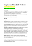
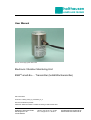
holthausen
elektronik GmbH
User Manual
Picture shows high-grade-steel-case
Electronic Vibration Monitoring Unit
ESW®-small-Ex-… Transmitter (hol660/Ex/transmitter)
date: 25/07/2013
document: hol660_small_ex_transmitter_hb_e
technical modification possible
holthausen elektronik GmbH is certified according to DIN EN ISO 9001
holthausen elektronik GmbH
Wevelinghoven 38
41334 Nettetal
phone: +49 (0) 21 53 - 40 08
fax: +49 (0) 21 53 - 89 99 4
[email protected]
www.holthausen-elektronik.de
holthausen
Electronic Vibration monitoring Unit
ESW®-small-Ex-…Transmitter
elektronik GmbH
Table of Contents
1. Generally basical safety-indications .............................. page 4
2. Packing and the transport ............................................. page 4
3. Application..................................................................... page 5
4. Measurement principle .................................................. page 6
5. Connection technology .................................................. page 6
6. Special conditions for safe use in Ex zones .................. page 8
7. Grounding concept ........................................................ page 9
8. Mounting of the vibration control unit ............................ page 10
9. Opening and closing of the vibration control unit........... page 11
10. Maintenance.................................................................. page 11
11. Display- and operation- elements.................................. page 11
12. Housing size.................................................................. page 12
13. Cable connection draft .................................................. page 13
14. Type registration ........................................................... page 14
Declaration of Conformity .............................................. appendix
Technical Data .............................................................. appendix
2
holthausen
Electronic Vibration monitoring Unit
ESW®-small-Ex-…Transmitter
elektronik GmbH
Important information
These operation instructions are to be read through completely and carefully heeded before
starting the device. Failure to heed or adhere can result in claims on manufacturer’s liability
becoming null and void for damages ensuing there from.
Manual action of any manner on the device – with the exception of proper procedures and
those described in these operation instructions – lead to forfeit of guarantee and exclusion
from liability.
The device is solely intended for the usage as described below. It is particularly not intended
for the direct or indirect protection of persons.
holthausen elektronik GmbH assumes no liability whatsoever as regards suitability for some
specific purpose.
If any question should remain open, please never hesitate to contact us.
holthausen elektronik GmbH
Wevelinghoven 38, 41334 Nettetal
Phone: +49 (0) 21 53 - 40 08
Fax: +49 (0) 21 53 - 8 99 94
Mail: [email protected]
3
holthausen
Electronic Vibration monitoring Unit
ESW®-small-Ex-…Transmitter
elektronik GmbH
1. Generally basical safety-indications
Don’t use this device as the only invigilator, if a malfunctioning of ESW ®-Compact/Ex could
lead to damages on goods or Persons.
To obtain the desired result be sure, that the device with its technical data fits to the bulk of
the object you want to supervise.
The sensor is sensitive to shock. A downfall out lower height to a hard substratum can
destroy the sensor.
The assembling place and the execution of the assembling of the sensor determine
decisively the quality of the sensor signal. The assembling may only happen through
qualified and instructed persons.
The electrical hook up is to be done by instructed persons. A mistake by the connection can
entail to faulty functions, outfall or ruination of the sensor and electronics.
The ESW ® should not be used on machines with a very energetic high-frequency solidborne. Through resonance apparitions in the sensor, the device can indicate a much too
great or too small value.
Powerful noise sources for instance inverters, in direct closeness of the sensor, electronics
or cabling, can result in faulty behaving of the apparatus.
Potential differences and balance currents in the mass guidance can result in faulty behaving
too.
The connection cable is resistant against many but not every type of chemical and
mechanical stress. Through a damaged cable chemicals could get inside the unit and
destroy the electronic. Then the unit would loose their function.
Therefore the conditions from the mounting surrounding must be checked. Then the cover
material from the cable have to be proofed if it resists these requirements. You can get an
overview from the chemical resistance of the cover material from us.
2. Packing and the transport
Note:
• The sensor is sensitive to shock. A downfall out lower height to an hard
substratum can destroy the sensor.
• Avoid to kink or tie a knot in the cable.
• Keep the electronic in a dry place.
• In case of a downfall or heckling or squeezing, could the casing or the operation
elements or the board get defects.
With adequate warning-labels and through a qualified packaging and storage, you can
protect the sensor and electronics at carriage against influences from outside.
4
holthausen
Electronic Vibration monitoring Unit
ESW®-small-Ex-…Transmitter
elektronik GmbH
3. Application
In many technical ranges there are vibrations, frequently are they to neglect or even
necessary, but sometimes also undesirable or even dangerous. Beside that, can
dangerously vibration-conditions start slinking or occur total unexpected.
The reason for it often lies in mechanical defectives or improper handling of the machine.
The sequences are maybe diminution of the product quality or even loss of production and
endangering of the security, at least a raised wear and tear.
Increasing automation as well as a high noise level, prevents often an acoustically or visual
surveillance. Thereby offers early detection, taking care of the material and limitation of
damage a considerable potential to the reduction in costs.
The ESW ®-small-Ex-Transmitter monitors the vibration level for continuous process and
outputs a current or voltage at the analog output, which is proportional to the vibration
acceleration.
The frequency range result from the characteristics of the measured object and the
environmental reference.
In order to tune the device optimally to the vibration problem, the measuring and frequency
range can be adapted ex-factory. Either the vibration speed or the vibration acceleration can
be selected as the quantity measured.
Depending on the measured object occurs the signal estimation according to the crest value
or the effective value of the measurement.
Particular attention should be donated to the assembling place of the sensor, decisively is
the source of the signal that shall be measured and its mean vibration direction.
The assembling place of the sensor and alignment of the measurement axis of the sensor
have to be selected so that the vibration possibly can be measured directly without
interferences, subdued crossings or defective couplings.
Attention: Pay attention on requirement by entrance in Ex-Zone
5
holthausen
Electronic Vibration monitoring Unit
ESW®-small-Ex-…Transmitter
elektronik GmbH
4. Measurement principle
The vibration-monitoring unit is generally mounted on the place, where inadmissible vibration
occurs or can be expected. The unit is permanently monitoring the real condition or situation
on the machine. The noticed mechanical vibration detected by
the sensor will be transformed to a corresponding electrical signal.
The sensor converts mechanical oscillations into an electrical alternating voltage. The
subsequent electronics converts the AC signal into a DC voltage, which is equivalent to the
measured oscillation speed. A current in the range 0 to 20mA or 4 to 20mA or a voltage in
the range 0 to 10V which is proportional to the measured value and corresponds to the
measuring range is delivered over the “analog output” cable terminals.
5. Connection technology
The ESW ®-small-Ex-Transmitter is available in two different basic versions.
Conventional technique
This version is designed in such a way that two conductors are used for power supply and
two conductors are used for the analog output.
Two-conductor technique
Although the term is defined, there are various interpretations of the same. In order to avoid
misunderstanding, a brief description of the use of the device is given below.
A) Voltage is measured across the load resistance, which is proportional to the current and thus
to the measured value:
(RL)
ESW
Load
resistance
+
Supply
Voltage
signal
B) The current is measured using an ammeter (e.g. SPS), which is proportional to the
Measured value:
+
ESW
4-20mA input
e.g. SPS
Supply
6
holthausen
Electronic Vibration monitoring Unit
ESW®-small-Ex-…Transmitter
elektronik GmbH
The voltage drop across the load resistance (sketch A) is directly proportional to the current
flowing through the resistor (Ohm's law: U = R x I) and thus corresponds to the acceleration.
An ammeter (sketch B) can, e.g., be the input (4 to 20mA) of an SPS.
The load resistance and the internal resistance of the current input may not exceed a certain
maximum value depending on the supply voltage.
The supply voltage must thus be selected in such a way that it is larger than the minimum
supply voltage (10V) and the voltage drop across the load and the internal resistance.
U b > U min + U R
The device operates linearly up to 22mA output current. However a maximum current of
27mA can occur when the measuring range is crossed.
Formula for calculation of the maximum load and internal resistance:
RL =
U b − U min
I max
Examples:
Supply: 12V DC
RL = (12V - 10V) / 27mA = 74 Ω max.
Supply: 24V DC
RL = (24V - 10V) / 27mA = 518,5 Ω max.
Supply: 30V DC
RL = (30V - 10V) ) / 27mA = 740,7 Ω max.
7
holthausen
Electronic Vibration monitoring Unit
ESW®-small-Ex-…Transmitter
elektronik GmbH
6. Special conditions for safe use in Ex zones
The ESW ®-small-Ex… is an operation resource for use in highly explosion-prone areas in
accordance with Directive 94/9/EC in the categories 2G (Zone 1) for gases and 2D (Zone 21)
for dusts. The exact range of application can be found on the label of the device.
Special conditions for application safety and instructions for using the device
The dimensions of the flameproof joints are in parts other than the relevant minimum or
maximum values of IEC 60079-1:2007. For information on the dimensions of the flameproof
joints contact the manufacturer.
The enclosure has to be integrated into the potential equalisation of the machine to be
monitored; this can be done either via the fastenings or via the connecting terminal. The
installer has to ensure that the equipotential bond is established by a qualified specialist in
accordance with the relevant VDE regulations.
Lead in and connection cable
The free cable end of the vibration monitor has to be connected either in an enclosure in one
the types of protection stated in sec. 1 of IEC60079-0:2007 or outside the explosive
atmosphere.
The open end of the supply cable must be connected in accordance with current wiring
regulations.
In applications in Zone 21 it must be ensured when installing the connection cable that
electrostatic charging cannot lead to ignitable discharges.
The lead in and the connection cable are supplied with the device and are certified for the
above mentioned application range for a minimum temperature resistance from - 60°C to
+90°C and comply with the requirements of the appli cable installation regulations.
Connection cable
Caution:
The device must never be transported suspended from the connecting cable. It is
not permitted to change the connection at the device or to change the cable.
Since the lead in does not have its own cable relief, the connecting cable must be fixed by
the user in the proximity of the lead in within a radius of approx. 20cm. The fixing must be
executed in such a manner that the cable has no kinks and it is not damaged.
General points to be observed
The operator, installer has to find out the Ex regulation applicable for his/her area of
application and comply with the same.
The temperature specifications refer to values without pouring. When pouring, the installation
conditions should be observed.
The supply voltage must be power limited components and executed according to the
applicable Ex provisions.
8
holthausen
Electronic Vibration monitoring Unit
ESW®-small-Ex-…Transmitter
elektronik GmbH
7. Grounding concept
main control box
with power supply
optional
connection box
vibration
control unit
shield
shield
+Ub
-Ub
signal ground
signal ground
vibration control unit ground
local
vibration control unit ground
connection box ground
local
connection box ground
main control
box ground
local
main control box ground
If an isolated installation is not specially requested, usually through the attachment with
screws each case is connected to the local machine ground.
In big facilities with considerable energy consumption and distances between the machines
could such big potential difference be build up, that substantial balancing current on the
ground network will occur. Dependent on intensity of such currents is arising of interference’s
or damaging of the unit the result!
Potential differences could also arise on machines, with small distances not clear crossing of
ground potential for example painted color or movable parts like suspension mounting.
Energetic high frequency interference energy could be added to the measurement signalwire by inductivity or trough capacity that could change the real existing measurement value!
In this way, for example parallel going elements could act as coupling-capacitor and winded
up grounding cable could act like a cut off choke.
Memorize: Ground is not equal everywhere!
Check the situation
Plan the grounding concept
Select the facility / realization
9
holthausen
Electronic Vibration monitoring Unit
ESW®-small-Ex-…Transmitter
elektronik GmbH
8. Mounting of the vibration control unit
- Whole mounting-, connecting- and adjustment-work should be done from
qualified personal only!
- Protect the ESW®-small-Ex-Transmiter definitely against drop, stroke and other
mechanical shock!
- The case of the unit must be connected over the attachment or the ground-on-earthTerminal with the potential compensation of the monitored machine. The connection
must be extremely low resistive as well as for long time stable. Doing this, take
urgent notice to the valid VDE-regulations.
SW22
Surface
A
>18,0
10,0
max. top hole
screw locked M10x25
with LOCTITE protection
M10
0,03 A
>ø55
The ESW ®-small-Ex-Transmiter will be mounted via one threaded pin AM10*25 per DIN 913
on the machine to be monitored.
Important
1. Measuring axis has to be coinciding with vibration excitation axis
(see case drawing page 12).
2. Take note of the label with instruction notes.
3. The surface has to be plain, clean and free of paint and rust.
4. The tap hole has to be perpendicular to the surface and free of metal-cuttings or other
foreign material. Further more the tap hole and the screw have to be free of paint, rust,
grease or other isolating components.
5. The grub screw has to be locked with liquid thread protection against unintended
loosening.
6. The unit has to be fixed, tight on the surface.
7. The advises to „connection cable“ (page 8), as well as „Opening and closing of the
vibration control unit “ (page 11) are absolutely to note.
10
holthausen
Electronic Vibration monitoring Unit
ESW®-small-Ex-…Transmitter
elektronik GmbH
9. Opening and closing of the vibration control unit
The user must switch off the power supply, before opening the measurement unit. To open
the unit the user needs a 0,9mm type of wrench “inbus - key“ and a forehead key with twobore nut, with size of 4mm. The case cover is ensured with a M2 screw. These must be
loosened before opening of the case cover, with an “inbus - key”. After adjustment of the unit,
please control the position of the DIP-switches
Before closing the unit the O-Ring must be examine. You have to insert a new O-Ring
(43 x 2mm, Si 970 FL – original spare part) if the old one is brittle, deformed, damaged or
already a few month in use.
Please pay attention that the thread and the interior room is oil- and dirt- free. Cleaning
around and inside the unit should be done only with clean and dry cloth. The closing and the
sealing of the unit is done after app. seven pitches of cover-nut thread, and ensured via the
M2 screw.
Advises for dismantling
Before dismantling the measurement unit, the power supply must be switched off. The
connection cable has to be loosened from the supporting surface to avoid damaging of the
cable. The vibration control unit should be set free via a 22mm wrench key.
10. Maintenance
The ESW ®-small-Ex-Transmitter is maintenance free.
Tools for case cover opening:
0,9mm type of wrench (Inbus-key)
Adjustable forehead key for two bore nut size 4mm
Factory: H. Sartorius Nachf. GmbH & Co
phone +49 (0) 21 02 / 44 00 - 0
fax
+49 (0) 21 02 / 44 00 - 24
11. Display- and operation- elements
The display elements will be accessible after unscrewing the cover of the ESW ®-small-ExTransmitter.
Display elements
LED
green on
LED
Operating voltage “on“
11
holthausen
Electronic Vibration monitoring Unit
ESW®-small-Ex-…Transmitter
elektronik GmbH
12. Housing size (in mm), with optional ground on earth terminal
Case material: Aluminium-, V2A- or V4A
55 mm
max. 10mm top hole
(M10)
ground on earth
terminal 4mm²
(optional)
15 mm
76 mm
108,0 mm
measuring axis
picture 1
SW22
30 mm
The unit will be mounted via one threaded pin AM10*25 per DIN 913.
Height differs (for example shown above: ESW-small-Ex-2241)
Authorization N.B.:
Material:
Weight:
Protection:
Cable insertion:
BVS 08 ATEX E 088 X
Aluminium, high grade steel V2A or V4A
approx. 1500g
IP 68
CAPRI Type ADE 1F-4F, IP68, with Neopren-airtight ring
12
holthausen
Electronic Vibration monitoring Unit
ESW®-small-Ex-…Transmitter
elektronik GmbH
13. Cable connection draft
ESW ®-small-Ex-…Transmitter
Version in conventional technology:
+24V supply volt.
ground
white +24V supply voltage
brown : ground
yellow : analog output (+)
green : analog output (ground)
analog output
analog ground
shield : see page 9 - Grounding Concept
case
Regulary the cable shield ends here in the housing
and is isolated to the case
Version in two wire technology:
Current loop
Reference
potential
white : supply (+)
brown : supply (-)
Load or current
measuring input
case
shield : see page 9 - Grounding Concept
Regulary the cable shield ends here in the housing
and is isolated to the case
13
holthausen
Electronic Vibration monitoring Unit
ESW®-small-Ex-…Transmitter
elektronik GmbH
14. Type registration
The unit with the type registration ESW ®-small-Ex….. is certified by the ATEX guideline
94/9/EC for the use in gas-air-mixture under atmospheric conditions or burnable dust.
Labeling / Registration
holthausen
elektronik GmbH
wevelinghoven 38
D-41334 nettetal
www.esw.eu
®
TYPE : ESW -small-Ex ...
: -..°C ≤ Tamb ≤ +..°C
: II2G Ex d IIC T4 - T6 Gb
: II2D Ex tb IIIC T80°C - T115°C Db
: IP68
Ser. Nr.: Monat Jahr - Ser.Nr.
ATEX Zul. Nr.: BVS 08 ATEX E 088 X
0035
IECEx Zul. Nr.: IECEx BVS 13.0006 X
®
ESW is a registered trademark of holthausen elektronik GmbH, Wevelinghoven 38, 41334 Nettetal
14