1
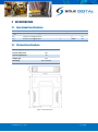
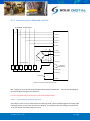
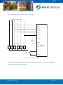
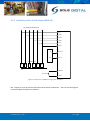
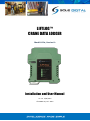
LIFTLOG™ CRANE DATA LOGGER Model LL10x, Version 6+ Installation and User Manual V1.7.3: 5/03/2015 © CASWA Pty Ltd – 2015 CONTENTS 1 OVERVIEW............................................................................................................................ 4 2 SPECIFICATIONS .................................................................................................................... 5 2.1 Operational Specifications ...................................................................................................... 5 2.2 Physical Specifications ............................................................................................................ 5 2.3 Electrical Specifications........................................................................................................... 6 2.4 Communication Specifications................................................................................................ 6 3 INSTALLATION DETAILS ......................................................................................................... 7 3.1 Prior to Installation ................................................................................................................. 7 3.2 Wiring Diagrams...................................................................................................................... 7 4 3.2.1 Installation with an existing load display ................................................................. 7 3.2.2 Installation with a Dedicated Load Cell .................................................................... 8 3.2.3 Installation with a 4-20mA Load Output .................................................................. 9 3.2.4 Installation with a 0-10V Load Output ................................................................... 10 3.2.5 Installation with a Q-Link Output (ABUS LIS) ......................................................... 11 3.2.6 Installation with a F-Link Output (ABUS LIS) .......................................................... 12 COMMISSIONING DETAILS .................................................................................................. 13 4.1 Installing and Launching the FSU Application ....................................................................... 13 4.1.1 FSU Program Installation........................................................................................ 13 4.1.2 Installing the FSU application ................................................................................. 13 4.1.3 Launching the application ...................................................................................... 13 4.2 Connecting to the Device ...................................................................................................... 14 4.3 Managing Firmware .............................................................................................................. 15 4.4 Checking the Date and Time ................................................................................................. 17 4.5 Liftlog™ Configuration Screen ............................................................................................... 17 4.5.1 Setting the Crane/Hoist Classifications .................................................................. 18 4.6 Calibrating the Liftlog™ ......................................................................................................... 19 4.6.1 Setting the Input Type ............................................................................................ 19 4.6.2 Using/Removing a HoistNet Input ......................................................................... 19 4.6.3 Using the Liftlog™ with a ControlPro ..................................................................... 20 © CASWA Pty Ltd – 2015 2 | Page 4.6.4 Checking the Gain .................................................................................................. 21 4.6.5 Setting the Zero Value............................................................................................ 22 4.6.6 Calibrating the Logger ............................................................................................ 22 4.7 Erasing the Calibration .......................................................................................................... 23 4.8 Checking the Inputs .............................................................................................................. 23 4.9 Setting the Crane ID .............................................................................................................. 24 4.10 Configuring the Overload ...................................................................................................... 25 4.10.1 Set Overload ........................................................................................................... 25 4.10.2 Overload Sensitivity ............................................................................................... 25 4.10.3 Invert Output.......................................................................................................... 25 4.11 Uploading Data ..................................................................................................................... 26 4.12 Erase Logger .......................................................................................................................... 26 4.13 AutoTare Setting ................................................................................................................... 27 4.13.1 Enter the tare load ................................................................................................. 27 4.13.2 Enable Auto-tare .................................................................................................... 27 4.14 Changing the Gain ................................................................................................................. 27 4.15 Running CheckIt Diagnostics ................................................................................................. 29 5 ROUTINE MAINTENANCE .................................................................................................... 30 5.1 Battery Maintenance ............................................................................................................ 30 6 TROUBLESHOOTING ............................................................................................................ 31 APPENDIX A: COMMUNICATION PROTOCOL ............................................................................... 32 APPENDIX B: FSU SYSTEM REQUIREMENTS ................................................................................. 34 APPENDIX C: DATA FILE FORMAT................................................................................................ 35 APPENDIX D: SIGNAL STRENGTH INDICATION FOR GOOD CALIBRATION ...................................... 36 © CASWA Pty Ltd – 2015 3 | Page 1 OVERVIEW Liftlog™ is a remaining life and load limiting data-logger for cranes that logs all hoisting motions as well as longitudinal and transverse travel. Accompanying software takes the wirelessly downloaded data and applies AS2550.1-2011 to calculate the remaining life of the crane. © CASWA Pty Ltd – 2015 4 | Page 2 SPECIFICATIONS 2.1 Operational Specifications Parameter Description Min Lcount Maximum number of logged events 10,000,000 Flog Frequency of logged events 4 Hz Tlog Duration of a logged event 30000 Sec 1 Typ Max Units 2.2 Physical Specifications Overall length (mm): 115 Overall width (mm): 100 Overall height (mm): 23 Weight (kg): Mounting: 0.12 30mm DIN Rail Figure 1: Case Dimensions © CASWA Pty Ltd – 2015 5 | Page 2.3 Electrical Specifications Parameter Description Min Vin Supply voltage 32 Iin Supply current 7 Vbatt Backup battery voltage 2 Ibatt Backup battery current Lmax Maximum voltage on a load sensing pin with respect to device gnd Lfs Load pin differential input for full scale reading 20 Iinput Input current draw (up, down, north, south, east, west pins) 0.05 Vmotion Max Units 250 VAC 8 12 mA 3 3.5 V 300 500 nA 7 V 23 25 mV 0.1 0.2 mA Max voltage for motion inputs 110 V AC Vfault Max voltage for fault output 250 V AC Ifault Max current sink by fault output 4 A Pfault Max contactor inrush rating at 48V 200 W Allowable operating temperature -40 Typ 85 Note1 °C Note1: Extended operation at maximum temperature will reduce the life the device. 2.4 Communication Specifications Communications between the device and a host is usually via a Bluetooth radio link. The Bluetooth device name will be set to the Crane ID, the PIN is 0000. For more details on the communication protocol used to communicate with the Liftlog™, see Appendix A. © CASWA Pty Ltd – 2015 6 | Page 3 INSTALLATION DETAILS 3.1 Prior to Installation Before installing your Liftlog™ device visually inspect the device and check that: (a) (b) (c) (d) the type of input marked on the front of the device is appropriate for your application; the case is not damaged and fits together securely; terminals are secure; terminal numbering is as per the following diagram. Figure 2: Terminal Positions NB: As each block of 4 terminals can be removed (for installation) it is important that they be reinstalled in the positions shown. 3.2 Wiring Diagrams 3.2.1 Installation with an existing load display The recommended method for connecting a Liftlog™ to an existing load display is to use a 4-20mA output from the display to a 4-20mA configured Liftlog™ or to insert a 4-20mA Liftlog™ into an existing current loop. Where this is not an option, it may be possible to piggyback the Liftlog™ onto the strain gauge inputs of the load display. © CASWA Pty Ltd – 2015 7 | Page 3.2.2 Installation with a Dedicated Load Cell To existing control circuit 3: Up 4: Down 5: North 6: South 7: East 8: West Red 9: +XCite 10:+Sense Green 11: -Sense White Black Contactor coils 12: -XCite 13: U D N S E W 14: Load limit 250VAC 4A 15,16: COM 0V 2: 240VAC 32-240V AC 1: 0VAC Figure 3: Connecting a dedicated load cell NB: Output pins (13-14) are Normally Closed and rated for 250V AC 4A. They can be reconfigured to Normally Open using the FSU software. It is very important not to connect pin 15,16 to the chassis earth! 3.2.2.1 Connecting the negative reference The Liftlog™ input circuit is connected to the chassis ground. When installing against an existing load Indicating system, ensure that its inputs are floating. It is important that the voltage on pins 10 and 11 do not exceed 3.3V with respect to pin 12. © CASWA Pty Ltd – 2015 8 | Page 3.2.3 Installation with a 4-20mA Load Output To existing control circuit 3: Up 4: Down 5: North 6: South 7: East 8: West 10: mA IN 4-20mA Signal 12: GND Contactor coils U D N S 13: E 14: W 0V Load limit 250VAC 4A 2: 240VAC 32-240V AC 1: 0VAC Figure 4: Connecting a 4-20mA load signal NB: Output pins (13-14) are Normally Closed and rated for 250V AC 4A. They can be reconfigured to Normally Open using the FSU software. © CASWA Pty Ltd – 2015 9 | Page 3.2.4 Installation with a 0-10V Load Output To existing control circuit 3: Up 4: Down 5: North 6: South 7: East 8: West 10: V IN 0-10V Signal 12: GND Contactor coils U D N S 13: E 14: W 0V Load limit 250VAC 4A 2: 240VAC 32-240V AC 1: 0VAC Figure 5: Connecting to a 0-10V Load Signal NB: Output pins (13-14) are Normally Closed and rated for 250V AC 4A. They can be reconfigured to Normally Open using the FSU software. © CASWA Pty Ltd – 2015 10 | Page 3.2.5 Installation with a Q-Link Output (ABUS LIS) To existing control circuit 3: Up 4: Down 5: North 6: South 7: East 8: West LIS Q Gnd 10: Q-Link 12: Gnd Contactor coils U D N S E W 0V 2: 240VAC 32-240V AC 1: 0VAC Figure 6: Connection to an ABUS LIS using a Q-Link ‘Q’ Output NB: Output pins (13-14) are Normally Closed and rated for 250V AC 4A. They can be reconfigured to Normally Open using the FSU software. © CASWA Pty Ltd – 2015 11 | Page 3.2.6 Installation with a F-Link Output (ABUS LIS) To existing control circuit 3: Up 4: Down 5: North 6: South 7: East 8: West LIS F1/F2 10: Q-Link Gnd 12: Gnd Contactor coils U D N S E W 0V 2: 240VAC 32-240V AC 1: 0VAC Figure 7: Connecting to an ABUS LIS using the Q-Link Frequency (F1/F2) Output NB: Output pins (13-14) are Normally Closed and rated for 250V AC 4A. They can be reconfigured to Normally Open using the FSU software. © CASWA Pty Ltd – 2015 12 | Page 4 COMMISSIONING DETAILS Liftlog™ is designed to be commissioned using a laptop computer. You will need a CASWA LINK-2 Bluetooth Modem and the Field Service Utility (FSU) software application loaded on a laptop. 4.1 Installing and Launching the FSU Application 4.1.1 FSU Program Installation Ensure that your computer is switched on, connected to the internet and that the minimum required software versions are installed (see Appendix B for minimum system requirements). Ensure that the LINK-2 modem is installed and that the drivers have loaded. 4.1.2 Installing the FSU application The latest LINK-2 FSU software (Link-2_FSU) can be downloaded from http://www.soledigital.com.au/Link2.html. You should check this location periodically for updates. 4.1.3 Launching the application Double click on the FSU program icon: © CASWA Pty Ltd – 2015 . 13 | Page 4.2 Connecting to the Device The FSU will scan for Bluetooth enabled devices. This process takes approximately 10 seconds, when complete a list of all CASWA devices within range will be displayed. Liftlog™ Units are depicted by a icon. If a particular Liftlog™ unit is not found, ensure it is powered up and press search. to repeat the NB: The Bluetooth link between the Laptop using a Link-2 and a Liftlog™ has a range of approximately 100m. To get help on Sole Digital products, go to our website or open a remote support session, press the icon. Otherwise, select the Liftlog™ you wish to configure by double clicking on the desired icon. © CASWA Pty Ltd – 2015 14 | Page 4.3 Managing Firmware If you running an older version of the FSU application on your laptop then you should update this before continuing. The process for updating the firmware on your Sole Digital device has changed. Firmware should only be updated if you: a) specifically want a new feature that is only available in later versions; b) are experiencing a problem that has been rectified by a later version; c) are experiencing a problem and need to roll back to an earlier firmware version that didn't cause the problem you are experiencing; or d) have been specifically instructed to do so by your Liftlog™ supplier. To check for new firmware versions or to access old firmware versions, return to the Device Display screen and right click the desired equipment icon. Select 'Manage Firmware'. A new window will popup and show the FSU software connecting to the device. When this is complete, the window will show the name of the device, its current firmware version and a list of newer firmware that is available for the device. © CASWA Pty Ltd – 2015 15 | Page If you need to roll back to an earlier version, check the 'Show old versions' box in the lower left corner of the window. Select a firmware version and then press the <Apply firmware> button that appears in the lower right corner of the window: The display will change to the following: As the message states, DO NOT switch off the Liftlog™ or the computer running the FSU software, or remove the Link2 modem until you are told to do so. If either device loses power then the Liftlog™ may become unusable and the device will need to be returned to your supplier for repair. When the firmware has finished updating successfully you will see a popup window and also be told to power cycle the device before reconnecting: message in the Close this window, wait for the manage firmware window to close (this may take 20 seconds) and power cycle the device as instructed. You will be returned to the first FSU screen, Manage Connections. Wait a few seconds after power cycling the device and then select the device you wish to connect to by double clicking the device. © CASWA Pty Ltd – 2015 16 | Page 4.4 Checking the Date and Time After checking for firmware the FSU application verifies whether the Liftlog™ has the same date/time as your computer. If the times are not the same, the following pop up window will display on the screen: When you press the <OK> button, the Liftlog™ time will be set to be the same as the laptop/PC. So before doing this, you should ensure the laptop is set up with the correct time and date. 4.5 Liftlog™ Configuration Screen Once firmware versions and date/time has been verified, the following screen will appear. This screen shows the: Crane ID (see section 4.9 for configuring this) Current Date/time on the device Total number of moves (contact closures) undertaken by the crane since the logger was installed (or card last formatted) Rated structure, hoist classifications and SWL fields Available battery voltage (only visible on old hardware versions) Current firmware version operating on the device © CASWA Pty Ltd – 2015 17 | Page It also contains a button (checkbox in lower left corner) to initiate CheckIt diagnostics. This is described in Section 0. 4.5.1 Setting the Crane/Hoist Classifications To facilitate more meaningful reporting and calculation of remaining life, the rated SWL and crane/hoist classifications are required. To set the classification of the crane/hoist, select the desired rating from the drop down menus. Enter the Safe Working Limit (SWL) of the crane in tonnes. Note: The Liftlog™ will still operate correctly without this information (i.e. all logging and load limiting functions will not be affected). However, this data will be required in order to produce automated or manual reports on remaining design life. © CASWA Pty Ltd – 2015 18 | Page 4.6 Calibrating the Liftlog™ If your Liftlog™ device has been preconfigured (only available with Q-Link inputs) or you are using a HoistNet load signal (which is calibrated) then you will not need to calibrate the Liftlog™. All other types of Liftlog™ must be calibrated. Unless you are connecting the device to a Konecranes ControlPro (and elect to use the already calibrated ControlPro settings), this process will require test weights. Click on the Load tab to bring up the load settings screen. 4.6.1 Setting the Input Type Make sure that the Input is set to the type of Liftlog™ input. By default, the mV/mA/V input will be selected. This is applicable for Liftlog™ devices that have a strain gauge, 4-20mA and 0-10V DC input. If you have a Q-Link or Frequency Liftlog™ (i.e. connected to an ABUS LIS unit) then you will need to change this selection. If you intend to use the Liftlog™ with a Konecranes ControlPRO make sure that you have selected the <mV,mA,V> input. 4.6.2 Using/Removing a HoistNet Input Liftlog™ devices are now compatible with CASWA HoistNet. This means that they can obtain their load signal wirelessly from any other HoistNet enabled device, eliminating the need for long cable runs between the load cell and data logger. To receive a load signal via HoistNet, select the HoistNet input and then press the <Bind> button: © CASWA Pty Ltd – 2015 19 | Page Note: HoistNet was first enabled in FSU version 10.7. If you do not see the HoistNet option, then you are running an old FSU version. Download and reinstall the lastest version of CASWA FSU. You may also need to update the firmware on your Liftlog™. A box will appear asking you which HoistNet enabled device you want to connect to: Select the device that has the load signal to be used and press <OK>. The popup box will close. The name of the bound HoistNet device will be shown on the Load screen. The connection status will also be shown: NB: You will need to ensure that the originating HoistNet load signal has been calibrated correctly. To unbind a Liftlog™ from a HoistNet device, or to change the bound device, press the <Bind> button on the Load screen and then select <Unbind> on the popup box. 4.6.3 Using the Liftlog™ with a ControlPro If your Liftlog™ device is connected to a Konecranes ControlPro and you want to use the calibration settings stored on the ControlPro (rather than calibrating with test weights) press the <Control Pro> button. A dialog box will appear asking you to confirm this action: © CASWA Pty Ltd – 2015 20 | Page Press <OK> to confirm. Another dialog box will appear. Enter the capacity of the hoist in tonnes and press <OK>. Your device is now calibrated and you will not need to zero or calibrate this hoist in order to use this Liftlog. NB: You need to have selected the <mV,mA,V> input type. 4.6.4 Checking the Gain A bar underneath the load display indicates the signal strength. It is important that the highlighted section of the bar moves to the right as load is increased and moves to the left as load is decreased. If the bar does not change at all, check your wiring from the load cell. A small change in the bar across a wide range of loads (e.g. zero to full load) indicates that the load signal requires more gain. © CASWA Pty Ltd – 2015 21 | Page Conversely, if the bar moves past the end of the scale then you have too much gain. The signal from the load cell is being clipped and load readings will be incorrect. The red box around the bar alerts you to this clipping. If this occurs, you need to reduce the gain in the Liftlog™. See section 4.14 for instructions on changing the gain. (NB: You will need to recalibrate the Liftlog™ after changing the gain.) For a summary table of what constitutes a good/bad calibration, see Appendix D. 4.6.5 Setting the Zero Value With no load on the hook (or the crane load display reading 0.00t), click on the <Zero> button. Within a few seconds the display will change to 0.0t: 4.6.6 Calibrating the Logger Lift a load (minimum 80% of rated capacity) and click the <Cal> button. Enter the mass shown on the load display when prompted and press <OK>. NB: If the fault output of the logger is used as an overload, you may need to go to the Overload screen and set a large overload limit (e.g. 3000) to allow the load to be lifted. See section 4.10 for details. © CASWA Pty Ltd – 2015 22 | Page Tap the <OK> button and the main screen will now display the load on the hook. NB: An overload will probably be shown (box becomes red) as the maximum load has not yet been set. 4.7 Erasing the Calibration Under some circumstances, it may be necessary to erase the calibration of a hoist. Warning: IF YOU ERASE THE CALIBRATION THEN YOU WILL NEED A TEST WEIGHT TO SET IT AGAIN (unless you are connected to an LIS via Q-Link or ControlPro)! To reset the calibration for a hoist, tap the <!> button. NB: Resetting the calibration of one hoist (main or aux) does not affect the calibration of the other. 4.8 Checking the Inputs To check the inputs, press the <Inputs> tab to bring up the following screen: The 'Active Inputs' boxes show the status of each of the Liftlog™’s input signals. They are intended to be used to confirm the correct wiring of the unit. The dropdown box can be used to adjust the duration an input must be activated in order to trigger an input. When a signal is detected, the respective box will be checked. © CASWA Pty Ltd – 2015 23 | Page This screen can also be used to disable inputs that are not connected. Disabling these will minimise the effects of spurious noise ingress on unused channels. Uncheck the box associated with any input that is not going to be connected on this Liftlog™. 4.9 Setting the Crane ID Setting the crane ID and overloads should be the last steps in configuring the device. Whilst the craneID is “unconfigured” and the overload is not set, the device will display lifts but not log them. This prevents data from lifts prior to calibration affecting later analysis. To set the crane ID click on the <General> button to return to the first screen. Type in the desired Crane identification in the ‘ID’ field. This must be 18 characters or less. If the logger will be used with the Liftlog™- AccessPack system, set the crane ID as directed by your AccessPack vendor or administrator of the AccessPack manager software at your location. Tip: Whilst you can set the Crane ID to anything you want, setting it to the crane’s serial number or other external marking will help you distinguish it from other logger equipped cranes. If you also include the crane classification such as C4M5 in the ID then the analysis software will use this in its calculations (if you haven't entered it separately on this screen). © CASWA Pty Ltd – 2015 24 | Page 4.10 Configuring the Overload This option is not available for loggers using an ABUS ‘Frequency’ or ‘Q-Link’ input (settings will be ignored). To set the overloads and/or to invert the output signal, press the ‘Overload’ tab to bring up the following screen: 4.10.1 Set Overload Enter the desired overload. This can be in 0.1t increments (E.g. 9.4). 4.10.2 Overload Sensitivity The overload sensitivity is controlled by a slider that changes how sensitive the overload is to short overloads caused by signal noise. Moving the slider to the right will make it less sensitive, so that it will effectively take longer to respond to a real overload event. Moving it to the left will make the logger respond quicker to real overloads, but also make it more susceptible spurious trips. You should set this slider as far to the left as possible without the overload tripping during normal operation. A text warning will display if this is set too high. 4.10.3 Invert Output The fault output on the Liftlog™ is a pair of normally closed contacts. Checking the <Output N/O> box will change the normally closed fault output to normally open. You may need to do this: If there is an interposing relay between the Liftlog™ and the up contactor; You want the Liftlog™ to operate in a “fail functional” rather than a “fail safe” mode; You are using the Liftlog™ for slack rope detection © CASWA Pty Ltd – 2015 25 | Page 4.11 Uploading Data To upload the logged data from the device to your computer, return to the General screen and click on the <Upload> button. This will bring up a dialog box asking where to save the data. The program defaults to your Documents folder. Enter the required file name (usually the crane name or serial number). The resulting data file is a .csv file and the format of its contents is described in Appendix C. 4.12 Erase Logger To erase all data from the logger, select the Reset tab to bring up the following screen: Press the <Reformat Card> button. You will be asked to confirm this action. NB: It is recommended that you upload data to your computer (see section 4.11) prior to erasing the logger. © CASWA Pty Ltd – 2015 26 | Page 4.13 AutoTare Setting When the Liftlog™ or load sensor may be exposed to large temperature swings or significant shock loads, it may be desirable to have the Liftlog™ retare periodically. To enable this, or to change the tare reset settings, press the ‘Auto tare’ tab. The default setting is for the auto-tare function to be disabled. 4.13.1 Enter the tare load The tare load is the presumed load on the unloaded crane. It includes lifting jigs, spreader bars etc. Enter the desired tare load in the <Tare Load> field. 4.13.2 Enable Auto-tare To enable the auto-tare function, click on the dropdown box and select the method you want to use to initiate the auto-tare function. Auto at power on will apply the tare load each time the Liftlog™ is powered on. Up 10 seconds will apply the tare load if the first move after powering up the Liftlog™ is ‘Up’ and this move has a duration of at least 10 seconds. Down 10 seconds will apply the tare load if the first move after powering up the Liftlog™ is ‘Down’ and this move has a duration of at least 10 seconds. 4.14 Changing the Gain When using a strain gauge load cell, Liftlog™ can be configured to one of 3 gain settings by moving an internal jumper. To change the gain, remove the internal board from the case. To do this, gently press the tabs on each side of the Liftlog™ and separate the end with the terminals from the main body. (The board will be attached to the terminals.) If you have already wired in the Liftlog™, remove the four terminal blocks first. © CASWA Pty Ltd – 2015 27 | Page Place the jumper into one of the following 3 positions. (A) Position 1 – No jumper or jumper off to one side. In this position, gain is set to the lowest setting, suitable for a 3mV/V load cell at full span. (B) Position 2 – Jumper bridges lower two terminals. In this position, gain is set to the medium setting, suitable for a 2mV/V load cell at full span. (C) Position 3 – Jumper bridges upper two terminals. In this position, gain is set to the maximum setting, suitable for a 1mV/V load cell at full span. © CASWA Pty Ltd – 2015 Lowest gain: Remove jumper or move to one side. Medium gain: Bridge lower two pins with jumper. Max gain: Bridge upper two pins with jumper. 28 | Page Reinsert the board into the case. If you removed the terminals, replace these too. See section 3.1 for their correct positions. You will need to recalibrate the Liftlog™ device after changing the gain. 4.15 Running CheckIt Diagnostics To confirm whether critical settings and parameters have been set sensibly, after completing the setup and commissioning of the Liftlog™ device, it is strongly recommended that you run CheckIt diagnostics (first introduced in version 11.9 of the FSU application). To initiate CheckIt Diagnostics, go to the General Tab and click on the check box in the lower left corner of the tab: A new window will appear and CheckIt Diagnostics will be initiated. During this process you may be asked to enter parameters (e.g. rated capacity of the hoist) to verify that critical settings have been entered and have saved correctly. Any potential issues or irregularities will be described in the CheckIt Diagnostics window. Press <Close> to return to the main FSU screen. © CASWA Pty Ltd – 2015 29 | Page 5 ROUTINE MAINTENANCE It is recommended that the Liftlog™ unit be inspected annually during which time: (a) logged data is downloaded from the device and saved to disk, and (b) the internal battery is checked and replaced if necessary. 5.1 Battery Maintenance The Button cell battery inside of the Liftlog™ device keeps the internal clock/calendar running when the logger has no external power. It should be checked by removing it from the logger and measuring its open circuit voltage. If this measurement is <2V then the battery should be replaced. © CASWA Pty Ltd – 2015 30 | Page 6 TROUBLESHOOTING Fault Cause Fix LED flashes RED on power up Unable to initialise memory card Cycle power. Load display indicates a fault Logger is affecting load pin voltages Check power to the logger. Disconnect pins 10 and 11 to verify that the logger is causing the fault. Replace /unit memory card. Check logger LED is operational (solid red or green). Check that the voltage from pins 11 and 12 is between 4 and 6 volts. If these voltages are out, check the connection between logger GND and load pin GND. Unable to connect to logger from FSU Logger or FSU are busy Power cycle the crane. Incorrect wiring Check that wiring is as per section 3.2. Check that removable terminals have been reinserted into their correct positions as shown in Figure 2. Pluggable terminals not seating correctly. Replace pluggable terminal and rewire the associated terminals. LED solid red on start-up Corrupt Memory Card Replace memory card. Multiple inputs trigger at the same time Cross talk on cabling Separate cables or fit 1W 1kOhm terminating resistors between the input terminal on the Liftlog™ and a GND terminal. Input(s) constantly on or flickering Active and neutral reversed Check and swap as necessary. Limit cuts out prematurely on hoisting and adjusting sensitivity has no effect Magnetic interference causing Liftlog™ to reset Check that Liftlog™ is at least 15mm from any large contactor. Adding Liftlog™ to a 420mA current loop causes a fault Liftlog™ is pulling the loop to GND Ensure the Liftlog™ is the lowest potential device in the loop or contact CASWA to order a 4-20mA isolator. © CASWA Pty Ltd – 2015 31 | Page APPENDIX A: COMMUNICATION PROTOCOL The host sends single character commands to the device to write or query parameters. Each command must be followed by a carriage return <CR>(ASCII 13). Where the command is a query command, no arguments are sent and the device will respond with a single line (except for the “u” and “E” commands) the requested value in ASCI text followed by a <CR>. Where the command is a set command, an argument may be included between the command and the <CR> . Where numbers are sent or received, they are sent as clear text; eg “1234” Where a number represents a load (eg the “o” and “O” commands, and the logged data returned by the “u” command), it is expressed in 100Kg units. Eg 3.5mt would be sent and received as 35. Where a number represents an elapsed time (eg in the logged data returned by the “u” command) it is expressed in 0.1second units. Eg. 35.4 seconds would be sent as 354. Where dates-time values are sent or received, they are sent in the format dd/mm/yy hh:mm . Hours are in 24 hour clock format. Leading zeros must be used. Eg 3/8/07 13:30 is an invalid datetime and should be sent as 03/08/07 13:30 © CASWA Pty Ltd – 2015 32 | Page Communication commands: Command v R/W Read Description Query the firmware version number. ? h Read Read H r Write Read i Read Display a summary of all settings Query the input mode: 0=Analog 1=Q-Link 2=Frequency Set the input mode Query the raw loadpin reading. The lifted load may be computed from this value as (Raw-Zero)/Cal. See the ”C” command. Query the device ID. I Write z Read Z c Write Read C Write on Read On Write wn Read Wn Write * Write © CASWA Pty Ltd – 2015 Set the device ID. Device ID’s are limited to 18 characters Query the zero parameter The zero value is used to calculate the actual load. See the “C”, and “r” commands/ Set the zero parameter. Query the cal parameter. The cal parameter is used to calculate the actual load. See the “C” and “r” commands Set the cal parameter. In normal operation, the cal parameter would be set as follows: Send the “r” command to get the raw reading from the load pin in it’s unloaded state. Send the “Z” command to set the zero parameter Apply a known load to the pin. Send the “r” command to get the raw reading from the load pin. Sent the “C” command to set the calibration value to (Rawunloaded-zero)*Known_Load (in 100Kg units) Query the overload (setpoint) parameter. This parameter is stored in 100Kg units, eg 3.5mt is expressed as 35. It is used by the device to determine when an overload occurs. Set the overload parameter. Example Send:v<CR> Rcv:1.02b<CR> Send:h<CR> Rcv:2<CR> Send:H0<CR> Send:r<CR> Rcv: 354<CR> Send: i<CR> Rcv: crane34<CR> Send: Icrane45<CR> Send: z<CR> Rcv: 34<CR> Send: Z23<CR> Send: c<CR> Rcv: 11<CR> Send: C9<CR> Send: o1<CR> Rcv: 35<CR> Send: O140<CR> Query the inverted status of a setpoint output. A return value of 1 means the output is normally open. Set the inverted status of a setpoint output. Send: w2<CR> Rcv: 1<CR> Send: W20<CR> Reboot the device. This command is usually only used to load new firmware onto the device Send: *<CR> 33 | Page APPENDIX B: FSU SYSTEM REQUIREMENTS The minimum requirements for operating CASWA’s Field Service Utility (FSU) and Link-2 Bluetooth modem are: Laptop computer running Windows XP SP3 or later; One Spare USB port; Microsoft .NET framework 3.5. © CASWA Pty Ltd – 2015 34 | Page APPENDIX C: DATA FILE FORMAT Data is recorded each time a motion is detected (a contactor closes). Each datum set contains: 1. Date/Time (based on the logger’s internal clock – when a user connects to the logger via Bluetooth using the FSU software, the time is compared to the time on the laptop and can be reset) 2. Operator (only used if a logger is bound to an AccessPack) 3. Hook (For Liftlog this will should always be 1.) 4. Load from load cell/other input in tenths of a tonne 5. Duration of motion in tenths of a second 6. Motion code – type of motion as shown in the following table. Motion Code Motion 0 No move 1 Move Up 2 Move Down 4 Move Fast 8 Move East 16 Move West 32 Move North 64 Move South 128 Move Up Fast 256 Move Aux1 / Aux 512 Move Aux2 / Magnet 1024 Move Aux3/Override 2048 Move Aux1 Off 4096 Move Aux2/Magnet Off 8192 Move Aux3/Override Off Note: If a combined motion is detected, then the sum of the individual motions is recorded (e.g. Move Up and Move Fast = 1+4=5). © CASWA Pty Ltd – 2015 35 | Page APPENDIX D: SIGNAL STRENGTH INDICATION FOR GOOD CALIBRATION During commissioning, or after adjusting gain by changing jumper settings, the Liftlog™ load circuitry needs to be calibrated. This calibration needs to ensure that all loads the crane is likely to measure will be within the allowable limits of the circuit, whilst maintaining enough sensitivity to detect any changes in load. Calibration involves setting a zero level and another value, typically between 80% and 100% of SWL. The signal strength bar, which is typically shown below the load output on the FSU screen provides a good indication of whether the calibration will have enough gain and sensitivity for the desired operation. Good and Bad calibration results are shown in the following tables. With no load on the hook: Reading Good/Bad Action BAD GOOD BAD Check wiring, increase gain Clear calibration, reduce gain With test weight lifted: % of SWL lifted Reading 80% 80% 80% 100% 100% 100% © CASWA Pty Ltd – 2015 Good/Bad Action BAD GOOD BAD Increase gain, check load cell BAD GOOD BAD Increase Gain Decrease gain Decrease Gain, check load cell wiring 36 | Page