1
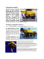
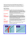
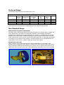
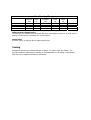
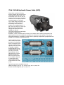
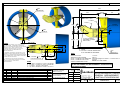
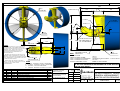
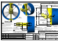
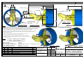
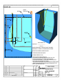
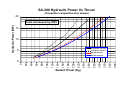
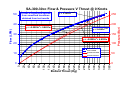
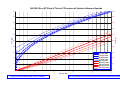
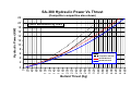
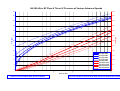
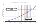
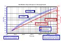
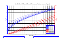
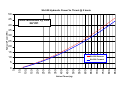
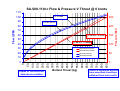
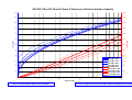
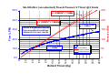
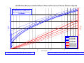
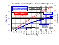
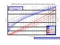
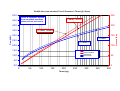
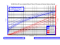
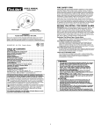
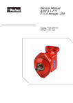
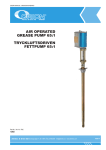
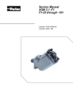
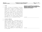
Performance
Hydraulic Propulsion Selection
Manual for Engineers
Revision 3 APR. 2003
Revision Record
Rev
1
2
3
Description
Original
SA300-20 and SA380-40 data added
Sa420-40 data added
By
cmi
cmi
cmi
Date
Dec 02
11/04/03
Propulsion Products
Since their launch in 1998, SubAtlantic's 'SA' range of hydraulic
thrusters have been selected for
approximately 90% of new build
cable burial/maintenance vehicles.
Working in this highly aggressive
environment, they have become
renown
for
their
reliability,
efficiency
and
exceptional
performance. The ROV sector is
now
also
recognising
the
considerable benefits to be gained,
having been selected for the
majority of 'new design' systems
such as Stolt Offshore’s, ’SOLO Mk
II’, Thales Geosolutions’s ‘G3’ or Deep Ocean’s ‘Installer’.
'SA' Range of Hydraulic Thrusters
We offer a 'Preferred Range' and a 'Non-Standard Range' of hydraulic thrusters.
Our 'Preferred Range' is available in
four sizes, SA300-30, SA380-40, SA42060 & SA500-110, where the first number
represents the diameter of the propeller
in millimetres and the second, the motor
displacement in cubic centimetres. The
SA300 and SA380 units are usually used
on work ROVs, the SA420 and SA500 for
cable ROVs.
Our 'Non-Standard Range' is available
in a number of different options of motor
displacement, propeller size, motor
manufacturer and mounting style. In certain cases, we can also produce specials to customer’s
requirements. Details of the SA-300-20cc and SA-380-30cc are shown in this manual.
When selecting hydraulic propulsion thrusters for an
underwater vehicle design, many highly important
considerations such as efficiency, pressure and flow, weight,
size and forward/reverse characteristics must be taken into
account. Failure to correctly interpret these or to use inaccurate
data will result in a system with inferior performance and
incapable of meeting your expectations.
During the development phases of the 'SA' range, Sub-Atlantic
evaluated various competitor's thruster products. We found
that the actual test results and weights proved to be vastly
different from the data claimed in their technical publications.
Infact, some of the data proved to be theoretically impossible to achieve. Sub-Atlantic therefore
introduced a policy to ensure that all our own test performance data was witnessed by a
reputable third party certification organisation (DNV). It is this commitment and confidence in our
product that will give you peace-of-mind. Remember and ask for independently witnessed test
data before you purchase your system or better still, test it yourself. If they can't provide it, ask
the question "why not"!
Main Features
In addition to peace-of-mind, our hydraulic thrusters will provide you with the following benefits:
Proven Reliability
Originating from the design of the shaft sealing system which
utilises hard, non-wearing ceramic and PTFE materials. Secondly, a
rugged VOAC bent axis piston motor is used, capable of clocking up
tens of thousands of trouble-free hours. We know SA thrusters are
reliable because we sell very little spare parts!
More Efficient
Our thrusters convert more thrust from the available hydraulic
power supply.
Superb
Forward/Reverse
Characteristics
Comparing input power to the output thrust, our forward and
reverse thrust curves fall within a 5% band. This is important in a
typical vectored configuration, as the overall system performance
will only be as good as the average forward/reverse thrust. For the
same power input, SA performance far exceeds other thrusters on
the market. Check out the comparison graph.
Lighter
This means less ROV buoyancy required, less in-water drag leading
to more usable thrust which means you will still be working when
the increasing current puts the other back on deck.
DNV Witnessed
Performance
Unlike some others, our thusters will perform just like we say they
will.
Retro-Fittable
SA thrusters use common mounting configurations so ROV
performance upgrades are easy.
Preferred Range
The standard Range consists of the following four units: -
Preferred Range
Model
SA-300-30
SA-380-40
SA-420-60
SA-500-110
Propeller
Diameter
mm
300
385
420
500
Motor
Displacement
cc
28.1
37.7
58.2
110.1
Bollard Thrust
@ 250bar
kgf
370
460
590
850
Weight in
Air
kg
18
27
34
59
Weight in
Water
kg
10
14
17
31
Mount
Flange
Flange
Flange
Flange
These are the most common types available and should be selected where possible.
Non-Standard Range
Different Motor/Propeller Combinations
The VOAC motors used all have identical mounting interfaces to the thruster body, no matter the
motor displacement. This makes them particularly suitable for interchanging with different
propeller sizes to obtain higher running efficiencies. For example, in an application where limited
hydraulic power and oil flow is available but maximum thrust is required, an SA-380-40 thruster
(which normally uses a 37.7 cc motor) can be simply fitted with a 28.1 cc motor and used instead
of an SA300-30. By using the larger propeller, increased efficiency can be achieved without the
requirement for more oil flow. Details of these are shown in this manual.
SA-300/1002-(20 or 30)
This is a version of the SA-300 with special mounting configuration to fit Innerspace 1002
brackets. This is a particularly useful option for carrying out a quick retrofit on ROVs with frames
with permanently welded thruster brackets such as 'Cobra'. Four to eight mounting studs can be
positioned to suit. The motor can be 20 or 30cc displacement depending on the oil flow available.
Non-Standard Range
Model
SA-300-20
SA-380-30
SA-300-1002-20
SA-300-1002-30
Propeller
Diameter
mm
300
385
300
300
Motor
Displ.
cc
19.0
28.1
19.0
28.1
Bollard Thrust
@ 250bar
kgf
230
330
230
370
Weight
In Air
kg
17
26
17
18
Weight in
Water
kg
9
13
9
10
Mount
Flange
Flange
Innerspace
Innerspace
Different Motor Manufacturers
Thrusters are also available with conversion kits which allow different motors to be used, such as
Rexroth. Contact and we will advise you of these options.
Special Sizes
In certain cases, we may be able to supply special sizes.
Testing
Sub-Atlantic thrusters are tested at a depth of approx. 2.7 metres below the surface. The
general procedure is illustrated on Drawing No. 0438-GA attached. All testing is witnessed by
DNV who issue a certified certificate of authenticity.
Installation Drawings
The following General Arrangement drawings are attached: Model
SA-300
SA-380
SA-420
SA-500
SA-300-1002
Thuster Test Rig
Drawing No.
0283-GA
0313-GA
0301-GA
0431-GA
1412-GA
0438-GA
Performance Graphs
Comprehensive graphs are attached which allow an engineer to fully quantify performance at
bollard condition through to 6 knots advance speed.
SA-300 Thrust versus Hydraulic Power
SA-300-30 cc Thrust versus Pressure & Flow @ 0 Knots
SA-380-30 cc Pressure versus Thrust & Flow @ 0, 1.5, 3.0, 4.5 & 6.0 Knots
SA-380 Thrust versus Hydraulic Power
SA-380-40 cc Thrust versus Pressure & Flow @ 0 Knots
SA-380-40 cc Pressure versus Thrust & Flow @ 0, 1.5, 3.0, 4.5 & 6.0 Knots
SA-420 Thrust versus Hydraulic Power
SA-420-60 cc Thrust versus Pressure & Flow @ 0 Knots
SA-420-60 cc Pressure versus Thrust & Flow @ 0, 1.5, 3.0, 4.5 & 6.0 Knots
SA-500 Thrust versus Hydraulic Power
SA-500-110 cc Thrust versus Pressure & Flow @ 0 Knots
SA-500-110 cc Pressure versus Thrust & Flow @ 0, 1.5, 3.0, 4.5 & 6.0 Knots
SA-300-20 cc (non-standard) Thrust versus Pressure & Flow @ 0 Knots
SA-380-20 cc (non-standard) Pressure versus Thrust & Flow @ 0, 1.5, 3.0, 4.5 & 6.0 Knots
SA-380-30 cc (non-standard) Thrust versus Pressure & Flow @ 0 Knots
SA-380-30 cc (non-standard) Pressure versus Thrust & Flow @ 0, 1.5, 3.0, 4.5 & 6.0 Knots
Other Equipment Available
Servo-Valve Pack
This extremely compact servo valve pack
weighs only 32 kg in air, 15 kg in sea
water and measures 775 x 198 x 213 mm.
This valve pack is generally used to provide
precise control of the propulsion thrusters on
underwater vehicles. The pack utilises 77 LPM
rated servovalves which provide low pressure
drop on most standard ROV applications. The
use of this pack in conjunction with SubAtlantic's efficient thrusters and hydraulic power
units, will produce an unbeatable propulsion
solution with regard to reliability, efficiency and
cost.
The valves can also be used to control any tool requiring a vazriable
speed or reversible function.The unit can use Star or Moog (Ultra)
valves. Unless specified, Sub-Atlantic supply the Star valve as standard
as this is half the weight of the Moog. Both types of valve are
functionally identical and interchangeable.
Features: ·
·
·
·
·
·
·
·
·
·
·
·
Compact and Lightweight
280 Bar maximum input pressure, 350 LPM maximum input flow rate
Pressure Relief Valve provides pump protection
Integral Soft Start Valve or Pump Remote Control Valve options
'STAR' lightweight Servo Valves rated 77 lpm full flow @ 70 bar pressure drop
Water Ingress Sensors located to suit all mounting orientations.
Temperature Sensor fitted to the return oil galley.
Various Control System Options
Integral Cover Relief Valve
Fully Captive Screw Assemblies. No more lost screws!
Lightweight Plastic Cover shaped to provide easy air bleeding and draining.
Options available
For full installation details, schematics, drawings, etc, request User Manual Doc. No. 1218-UM
75 & 110 kW Hydraulic Power Units (HPU)
These HPUs are ideal for driving
thruster systems and hydraulic tools
requiring higher power inputs. The
submersible motor unit can also be
used to drive other types of rotating
machinery such as water pumps for
trenching machines. The motor
uses a Zeihl-Abegg rotor/stator unit
which has for many years been
successfully used in the ROV
industry. The standard motor is 4
pole, 3000 vac running at 1700 rpm
full load speed @ 60Hz. Other
voltage and speed options are
available on request.
The motor body and end cap design
provides for efficient heat
dissipation, which is essential when working in hot climates. Motor winding temperature and
water ingress sensors are included for connection to customers control system. The motor is
filled with transformer or hydraulic oil which must be positively compensated (compensators are
available, see Hydraulic Products Brochure).
Various hydraulic pumps
can be fitted to the motor
by means of an Interface
Plate. A secondary pump
can also be fitted to the
opposite end of the motor
to provide a separate
isolated hydraulic circuit.
Compensated pumps are
generally used which
automatically 'unload'
when there is no power
demand. Pumps from
different manufacturers
such a VOAC or Rexroth
in various sizes and
control options can be
supplied fitted and ready
to run.
Typical Pump Options Available Sizes (cc)
VOAC PV Range 16, 20, 23, 32, 40, 46, 63, 80, 92, 140, 180, 270
Rexroth A10VSO Range 28, 45, 71, 100, 140
THIRD ANGLE PROJECTION
THE INFORMATION CONTAINED IN THIS DRAWING IS THE SOLE PROPERTY OF SUB-ATLANTIC LTD. ANY REPRODUCTION IN PART OR WHOLE WITHOUT THE WRITTEN PERMISSION OF SUB-ATLANTIC IS PROHIBITED
465
300
PROPELLER
205
80
165
PORTS A & B
PORT D
PORT C
CENTRE
OF MASS
189
40°
368
NOZZLE
183.5
18
SEE NOTE 1
NOTES
3. ENSURE THAT THE MOTOR CASE DRAIN
PORT 'C' IS FILLED WITH HYDRAULIC OIL PROIR
TO INITIAL START-UP AND SYSTEM
COMMISSIONING.
50
48
21
4 HOLES 13
FOR M12 BOLTS
82
DATA
80
CGM
6/09/02
30/09/98
REV
BY
DATE
EBR
NOTES UPDATED
CMI
APPROVED FOR CONSTRUCTION
DESCRIPTION
RECORD OF REVISIONS
35
FINISH
HARD ANODISING & POWER
PAINT COATINGS
USO, TOLERANCES TO BE
APP
NOTE:
MOTOR CAN BE ORIENTATED
IN 90 DEGREE INCREMENTS
12
SEE NOTE 1
17.4 kG
9.8 kG
250 BAR (Higher Possible - Consult Tech. Dept.)
56 LPM
REFER TO DATA SHEET
OTHER THRUSTERS AVAILABLE : SA-380, SA-420 & SA-500,
SA-300-1002 INNERSPACE REPLACEMENTS & OTHER SPECIALS.
ASK FOR DATA SHEETS
1/2" BSPP - HYDRAULIC SUPPLY OR RETURN
3/4" BSPP - HYDRAULIC SUPPLY OR RETURN
1/2" BSPP - MOTOR CASE DRAIN
1/8" BSPP - BEARING HOUSING OIL SUPPLY
MATERIAL
ALUMINIUM, STAINLESS
STEEL & PLASTICS
2
1
5 OFF HOUSING
AIR BLEED POINTS
SEE NOTE 2
WEIGHT IN AIR:
WEIGHT IN SEA WATER:
MAX. CONTINUOUS PRESSURE:
MAX. CONTINUOUS FLOW:
THRUST, PRESSURE, FLOW:
122
PORTS
'A'
'B'
'C'
'D'
169
75
1. THRUSTER IS FIXED BY 4 OFF M12 BOLTS TO
HOST STRUCTURE. IF REQUIRED ADDITIONAL
M10 BOLT CAN BE FITTED THROUGH THE TORQUE
RESTRAINT HOLE. USING THIS HOLE WILL
ELIMINATE TORQUE EFFECTS TO THE HOST
STRUCTURE BUT IS NOT REQUIRED FOR
THRUSTER STRENGTH.
2. BEARING HOUSING IS SUPPIED WITH 5 OFF
AIR BLEED POINTS POSITIONED TO ALLOW THE
REMOVAL OF AIR WITH THE THRUSTER MOUNTED
IN ANY ORIENTATION. TWIST SCREW ONE TURN
TO BLEED AIR THEN TIGHTEN.
10
78
WT AIR
-
WT WATER
kg (E) kg (E)
DRAWN
DATE
CHECK
APPRV.
ENGR.
CGM
30/09/98
SSM
CMI
CGM
PROJECT
HYDRAULIC THRUSTERS
TITLE
Unit 12, Airways Industrial Estate
Pitmedden Road, Dyce.
Aberdeen. U.K.
AB21 0DT
Tel: ++44 (0) 1224 723623
Fax: ++44 (0) 1224 723822
SA-300 HYDRAULIC THRUSTER
GENERAL ARRANGEMENT
& INSTALLATION DRAWING
SCALE (USO) ORIG. SIZE DOC.
No.
1 : 3.5
A3
0283-GA
SHEET
1 of 1
REV
2
THIRD ANGLE PROJECTION
THE INFORMATION CONTAINED IN THIS DRAWING IS THE SOLE PROPERTY OF SUB-ATLANTIC LTD. ANY REPRODUCTION IN PART OR WHOLE WITHOUT THE WRITTEN PERMISSION OF SUB-ATLANTIC IS PROHIBITED
515
385
PROPELLER
210
80
207
PORTS A & B
CENTRE
OF MASS
PORT D
PORT C
240
12
40°
79
472
NOZZLE
NOTES
235
18
SEE NOTE 1
82
2. BEARING HOUSING IS SUPPIED WITH 5 OFF
AIR BLEED POINTS POSITIONED TO ALLOW THE
REMOVAL OF AIR WITH THE THRUSTER MOUNTED
IN ANY ORIENTATION. TWIST SCREW ONE TURN
TO BLEED AIR THEN TIGHTEN.
3. ENDURE THAT THE MOTOR CASE DRAIN
PORT 'C' IS FILLED WITH HYDRAULIC OIL PROIR
TO INITIAL START-UP AND SYSTEM
COMMISSIONING.
5 OFF HOUSING
AIR BLEED POINTS
SEE NOTE 2
50
1. THRUSTER IS FIXED BY 4 OFF M12 BOLTS TO
HOST STRUCTURE. IF REQUIRED ADDITIONAL
M10 BOLT CAN BE FITTED THROUGH THE TORQUE
RESTRAINT HOLE. USING THIS HOLE WILL
60
ELIMINATE TORQUE EFFECTS TO THE HOST
STRUCTURE BUT IS NOT REQUIRED FOR
THRUSTER STRENGTH.
4 HOLES 13
FOR M12 BOLTS
21
DATA
80
1" BSPP - HYDRAULIC SUPPLY OR RETURN
3/4" BSPP - HYDRAULIC SUPPLY OR RETURN
1/2" BSPP - MOTOR CASE DRAIN
1/8" BSPP - BEARING HOUSING OIL SUPPLY
SSM
CGM
11/01/99
REV
BY
DATE
05/09/2002 EXTRA NOTES ADDED
APPROVED FOR CONSTRUCTION
DESCRIPTION
RECORD OF REVISIONS
CMI
FINISH
HARD ANODISING & POWER
PAINT COATINGS
CMI
USO, TOLERANCES TO BE
APP
NOTE:
MOTOR CAN BE ORIENTATED
IN 90 DEGREE INCREMENTS
12
SEE NOTE 1
27 kG
WEIGHT IN AIR:
14 kG
WEIGHT IN SEA WATER:
MAX. CONTINUOUS PRESSURE: 250 BAR (Higher Possible - Consult Tech. Dept.)
70 LPM
MAX. CONTINUOUS FLOW:
REFER TO DATA SHEET
THRUST, PRESSURE, FLOW:
OTHER THRUSTERS AVAILABLE: SA-300, SA-420, SA-500,
SA-300-1002 INNERSPACE REPLACEMENTS & OTHER SPECIALS.
ASK FOR DATA SHEETS
122
MATERIAL
ALUMINIUM, STAINLESS
STEEL & PLASTICS
2
1
77
PORTS
'A'
'B'
'C'
'D'
55
220
WT AIR
-
WT WATER
kg (E) kg (E)
DRAWN
DATE
CHECK
APPRV.
ENGR.
CGM
11/01/99
MBI
RWR
CGM
PROJECT
HYDRAULIC THRUSTERS
TITLE
Unit 12, Airways Industrial Estate
Pitmedden Road, Dyce.
Aberdeen. U.K.
AB21 0DT
Tel: ++44 (0) 1224 723623
Fax: ++44 (0) 1224 723822
SA-380 HYDRAULIC THRUSTER
GENERAL ARRANGEMENT
& INSTALLATION DRAWING
SCALE (USO) ORIG. SIZE DOC.
No.
1:4
A3
0313-GA
SHEET
1 of 1
REV
2
THE INFORMATION CONTAINED IN THIS DRAWING IS THE SOLE PROPERTY OF SUB-ATLANTIC LTD. ANY REPRODUCTION IN PART OR WHOLE WITHOUT THE WRITTEN PERMISSION OF SUB-ATLANTIC IS PROHIBITED
DUE TO OUR POLICY OF CONTINUAL PRODUCT DEVELOPMENT, SUB-ATLANTIC RESERVE THE RIGHT TO CHANGE THE INFORMATION CONTAINED IN THIS DRAWING WITHOUT PRIOR NOTICE.
THIRD ANGLE PROJECTION
548
420
PROPELLER
PORTS A & B
163
144
225
PORT D
CENTRE
OF MASS
PORT C
262
127
19
40°
79
515
NOZZLE
183
256
24
SEE NOTE 1
NOTES
19
144
76
108
DATA
60
4 HOLES 13
FOR M12 BOLTS
MATERIAL
ALUMINIUM, STAINLESS
STEEL & PLASTICS
6/09/02
2
1
26/01/99
30/09/98
REV
BY
DATE
INFORMATION UPDATED
MOUNTING DETAILS ALTERED
CMI
CMI
APPROVED FOR CONSTRUCTION
CMI
DESCRIPTION
RECORD OF REVISIONS
14
SEE NOTE 1
APP
FINISH
HARD ANODISING & POWER
PAINT CAOTINGS
USO, TOLERANCES TO BE
34 kG
17 kG
250 BAR (Higher Possible - Consult Tech. Dept.)
99 LPM
REFER TO DATA SHEET
OTHER SIZES AVAILABLE: SA-300, SA-380 & SA-500,
SA-300-1002 INNERSPACE REPLACEMENTS & OTHER SPECIALS
ASK FOR DATA SHEETS
- HYDRAULIC SUPPLY OR RETURN
'B' 3/4" BSPP - HYDRAULIC SUPPLY OR RETURN
'C' 1/2" BSPP - MOTOR CASE DRAIN
'D' 1/8" BSPP - BEARING HOUSING OIL SUPPLY
EBR
CGM
CGM
5 OFF HOUSING
AIR BLEED POINTS
SEE NOTE 2
WEIGHT IN AIR:
WEIGHT IN SEA WATER:
MAX. CONTINUOUS PRESSURE:
MAX. CONTINUOUS FLOW:
THRUST, PRESSURE, FLOW:
3. ENSURE THAT THE MOTOR CASE DRAIN
PORT 'C' IS FILLED WITH HYDRAULIC OIL PROIR PORTS
TO INITIAL START-UP AND SYSTEM
'A' 1" BSPP
COMMISSIONING.
3
NOTE MOTOR CAN
BE ORIENTATED IN
90 INCREMENTS
137
1. THRUSTER IS FIXED BY 4 OFF M12 BOLTS TO
HOST STRUCTURE. IF REQUIRED ADDITIONAL
M12 BOLT CAN BE FITTED THROUGH THE TORQUE
RESTRAINT HOLE. USING THIS HOLE WILL
ELIMINATE TORQUE EFFECTS TO THE HOST
STRUCTURE BUT IS NOT REQUIRED FOR
THRUSTER STRENGTH.
2. BEARING HOUSING IS SUPPIED WITH 5 OFF
AIR BLEED POINTS POSITIONED TO ALLOW THE
REMOVAL OF AIR WITH THE THRUSTER MOUNTED
IN ANY ORIENTATION. TWIST SCREW ONE TURN
TO BLEED AIR THEN TIGHTEN.
238
WT AIR
-
WT WATER
kg (E) kg (E)
DRAWN
DATE
CHECK
APPRV.
ENGR.
CGM
30/09/98
MBI
RWR
CGM
PROJECT
HYDRAULIC THRUSTERS
TITLE
Unit 12, Airways Industrial Estate
Pitmedden Road, Dyce.
Aberdeen. U.K.
AB21 0DT
Tel: ++44 (0) 1224 723623
Fax: ++44 (0) 1224 723822
SA-420 HYDRAULIC THRUSTER
GENERAL ARRANGEMENT
& INSTALLATION DRAWING
SCALE (USO) ORIG. SIZE DOC.
No.
1:4
A3
0301-GA
SHEET
1 of 1
REV
3
THE INFORMATION CONTAINED IN THIS DRAWING IS THE SOLE PROPERTY OF SUB-ATLANTIC LTD. ANY REPRODUCTION IN PART OR WHOLE WITHOUT THE WRITTEN PERMISSION OF SUB-ATLANTIC IS PROHIBITED
DUE TO OUR POLICY OF CONTINUAL PRODUCT DEVELOPMENT, SUB-ATLANTIC RESERVE THE RIGHT TO CHANGE THE INFORMATION CONTAINED IN THIS DRAWING WITHOUT PRIOR NOTICE.
THIRD ANGLE PROJECTION
634
500
PROPELLER
200
PORTS A & B
144
PORT D
CENTRE
OF MASS
PORT C
315
265
40°
23
108
613
NOZZLE
305
29
SEE NOTE 1
280
NOTE MOTOR CAN
BE ORIENTATED IN
90 INCREMENTS
18
SEE NOTE 1
NOTES
1. THRUSTER IS FIXED BY 4 OFF M12 BOLTS TO
HOST STRUCTURE. IF REQUIRED ADDITIONAL
M16 BOLT CAN BE FITTED THROUGH THE TORQUE
RESTRAINT HOLE. USING THIS HOLE WILL
ELIMINATE TORQUE EFFECTS TO THE HOST
STRUCTURE BUT IS NOT REQUIRED FOR
THRUSTER STRENGTH.
2. BEARING HOUSING IS SUPPIED WITH 5 OFF
AIR BLEED POINTS POSITIONED TO ALLOW THE
REMOVAL OF AIR WITH THE THRUSTER MOUNTED
IN ANY ORIENTATION. TWIST SCREW ONE TURN
TO BLEED AIR THEN TIGHTEN.
3. ENSURE THAT THE MOTOR CASE DRAIN
PORT 'C' IS FILLED WITH HYDRAULIC OIL PROIR
TO INITIAL START-UP AND SYSTEM
COMMISSIONING.
72
76
108
2
1
CGM
13/09/02
08/10/99
REV
BY
DATE
127
DATA
4 HOLES 13
FOR M12 BOLTS
(HIGH STRENGTH)
19
183
PORTS
'A'
'B'
'C'
'D'
OTHER THRUSTERS AVAILABLE: SA-300, SA-380 & SA-420.
SA-300-1002 INNERSPACE REPLACEMENTS & OTHER SPECIALS.
ASK FOR DATA SHEETS
1-1/4" BSPP - HYDRAULIC SUPPLY OR RETURN
1" BSPP - HYDRAULIC SUPPLY OR RETURN
1/2" BSPP - MOTOR CASE DRAIN
1/8" BSPP - BEARING HOUSING OIL SUPPLY
FINISH
HARD ANODISING & POWER
PAINT CAOTINGS
NOTES UPDATED ECN-029-02
PRELIMINARY FOR INFORMATION
DESCRIPTION
RECORD OF REVISIONS
CMI
APP
USO, TOLERANCES TO BE
5 OFF HOUSING
AIR BLEED POINTS
SEE NOTE 2
WEIGHT IN AIR:
59 kG
WEIGHT IN SEA WATER:
31 kG
MAX. CONTINUOUS PRESSURE: 250 BAR (Higher Possible - Consult Tech. Dept.)
MAX. CONTINUOUS FLOW:
154 LPM
THRUST, PRESSURE, FLOW:
REFER TO DATA SHEET
144
MATERIAL
ALUMINIUM, STAINLESS
STEEL & PLASTICS
EBR
127
WT AIR
-
WT WATER
kg (E) kg (E)
DRAWN
DATE
CHECK
APPRV.
ENGR.
CGM
08/10/99
MBI
RWR
CGM
PROJECT
HYDRAULIC THRUSTERS
TITLE
Unit 12, Airways Industrial Estate
Pitmedden Road, Dyce.
Aberdeen. U.K.
AB21 0DT
Tel: ++44 (0) 1224 723623
Fax: ++44 (0) 1224 723822
SA-500 HYDRAULIC THRUSTER
GENERAL ARRANGEMENT
& INSTALLATION DRAWING
SCALE (USO) ORIG. SIZE DOC.
No.
1:5
A3
0431-GA
SHEET
1 of 1
REV
2
THIRD ANGLE PROJECTION
THE INFORMATION CONTAINED IN THIS DRAWING IS THE SOLE PROPERTY OF SUB-ATLANTIC LTD. ANY REPRODUCTION IN PART OR WHOLE WITHOUT THE WRITTEN PERMISSION OF SUB-ATLANTIC IS PROHIBITED
470
3.0
= 76.2 =
13.0
330.2 PCD
12 TYP. MOUNT THICKNESS
PORTS A & B
M12 MOUNTING STUDS
38.1 TYP
78
273
197
150
PORT D
PORT C
CENTRE
OF MASS
M12 MOUNTING STUDS
40°
345
5 OFF HOUSING
300
AIR BLEED POINTS
PROPELLER SEE NOTE 2
STANDARD VERSION
NOTES
368
6
'TUNNEL' VERSION
214
STANDARD VERSION
MOTOR CAN BE ORIENTATED
IN 90 DEGREE INCREMENTS
1. THE THRUSTER IS AVAILABLE IN A STANDARD VERSION AND A 'TUNNEL VERSION. THE TUNNEL VERSION IS USED
WHEN AVAILABLE SPACE IS LIMITED SUCH AS INSIDE SOME EXISTING BUOYANCY DESIGNS. THE ONLY DIFFERENCE
BETWEEN THE TWO IS THE SYLE OF THE NOZZLE WHICH ARE INTERCHANGEABLE. THE THRUSTERS ARE FIXED BY
4 OR 8 OFF M12 STUDS WHICH PICK UP EXISTING INNERSPACE 1002 MOUNTING BRACKETS. STUDS CAN BE
SUPPLIED IN DIFFERENT LENGTHS TO REPOSITION THE RELATIVE POSITION OF THE THRUSTER.
2. BEARING HOUSING IS SUPPIED WITH 5 OFF AIR BLEED POINTS POSITIONED TO QUICKLY ALLOW THE
REMOVAL OF AIR WITH THE THRUSTER MOUNTED IN ANY ORIENTATION. TWIST SCREW ONE TURN
TO BLEED AIR THEN TIGHTEN.
3. ENSURE THAT THE MOTOR CASE DRAIN PORT 'C' IS FILLED WITH HYDRAULIC
OIL PROIR TO INITIAL START-UP AND SYSTEM COMMISSIONING.
4. THRUSTER CAN BE SUPPLIED WITH EITHER 20cc OR 30cc MOTOR DEPENDING
ON HYDRAULIC SYSTEM CAPABILITY (CONSULT SUB-ATLANTIC FOR SYSTEM ANALYSIS).
30 cc MOTOR SHOWN.
PORTS
'A'
'B'
'C'
'D'
1/2" BSPP - HYDRAULIC SUPPLY OR RETURN
3/4" BSPP - HYDRAULIC SUPPLY OR RETURN
1/2" BSPP - MOTOR CASE DRAIN
1/8" BSPP - BEARING HOUSING OIL SUPPLY
WEIGHT IN AIR:
WEIGHT IN SEA WATER:
MAX. CONTINUOUS PRESSURE:
MAX. CONTINUOUS FLOW:
THRUST, PRESSURE, FLOW:
18.4 kG
10.9 kG
250 BAR (Higher Possible - Consult Tech. Dept.)
56 LPM
REFER TO DATA SHEET
MATERIAL
ALUMINIUM, STAINLESS
STEEL & PLASTICS
1
A
EBR
CMI
4/09/02
22/11/01
REV
BY
DATE
ISSUED FOR CONSTRUCTION
CMI
FINISH
HARD ANODISING & POWER
PAINT COATINGS
ISSUED FOR APPROVAL
CMI
USO, TOLERANCES TO BE
DESCRIPTION
RECORD OF REVISIONS
APP
STANDARD VERSION
'TUNNEL' VERSION
WT AIR
-
WT WATER
kg (E) kg (E)
DRAWN
DATE
CHECK
APPRV.
ENGR.
CMI
22/11/01
MBI
CMI
CMI
PROJECT
HYDRAULIC THRUSTERS
TITLE
Unit 12, Airways Industrial Estate
Pitmedden Road, Dyce.
Aberdeen. U.K.
AB21 0DT
Tel: ++44 (0) 1224 723623
Fax: ++44 (0) 1224 723822
SA-300-1002 HYD. THRUSTER
GENERAL ARRANGEMENT
& INSTALLATION DRAWING
SCALE (USO) ORIG. SIZE DOC.
No.
1:4
A3
1412-GA
SHEET
1 of 1
REV
1
THIRD ANGLE PROJECTION
THE INFORMATION CONTAINED IN THIS DRAWING IS THE SOLE PROPERTY OF SUB-ATLANTIC LTD. ANY REPRODUCTION IN PART OR WHOLE WITHOUT THE WRITTEN PERMISSION OF SUB-ATLANTIC IS PROHIBITED
IF IN DOUBT - ASK!
CALIBRATED
TENSILE LOAD CELL
MOUNTING
FLANGE
2710 APPROXIMATE TEST DEPTH
PIVOT POINT
2692 PIVOT TO LOAD WIRE
2748 PIVOT TO MOUNTING FLANGE
WATERLINE
PULLEY FIXED
TO TANK WALL
THRUST
'A'
6 mm LOAD WIRE
BOLLARD THRUST =
LOAD CELL READING x 2692
________________________
3811 APPROXIMATE
( 2748 + 'A' )
PRESSURE IS RECORDED DIRECTLY AT MOTOR INLET AND OUTLET ON CALIBRATED
PRESSURE GAUGES. TEST PRESSURE = INLET PRESSURE MINUS OUTLET PRESSURE.
THRUSTER SHOWN IN
FORWARD TEST SET-UP
MOTOR INLET FLOW IS RECORDED ON CALIBRATED FLOW METER.
OIL TEMPERATURE IS RECORDED FROM FLOWMETER.
CASE DRAINAGE IS RECORDED AT 200 BAR.
OUTLINE TEST PROCEDURE (FORWARD & REVERSE TESTS)
1. SET FLOW RATE AT 5 LPM, SWITCH OFF FLOW AND ALLOW WATER IN TANK TO SETTLE,
SWITCH ON FLOW, RECORD INLET & OUTLET PRESSURES, LOAD CELL & FLOW RATE.
2. SET FLOW RATE AT NEXT INCREMENT (e.g. 7.5 LPM), SWITCH OFF FLOW AND ALLOW WATER
TO SETTLE, SWITCH ON FLOW AND TAKE NEXT SET OF READINGS.
3. REPEAT AS ABOVE FOR FLOW INCREMENT STEPS UNTIL THE MAXIMUM MOTOR PRESSURE IS REACHED.
4. REMOVE TEST FRAME, REVERSE THRUSTER ON FRAME, RELACE IN TANK AND CARRY OUT TESTS
AS ABOVE TO CHECK REVERSE BOLLARD THRUST.
MATERIAL
-
FINISH
-
-
-
-
1
CMI
REV
BY
28/01/99
DATE
USO, TOLERANCES TO BE
APPROVED FOR CONSTRUCTION
DESCRIPTION
RECORD OF REVISIONS
APP
-
WT WATER
WT AIR
-
kg (E)
-
DRAWN
CMI
DATE
PROJECT
CHECK
28/01/99
MBI
APPRV.
RWR
ENGR.
RWR
HYDRAULIC THRUSTERS
TITLE
kg (E)
Unit 12, Airways Industrial Estate
Pitmedden Road, Dyce.
Aberdeen. U.K.
AB21 0DT
Tel: ++44 (0) 1224 723623
Fax: ++44 (0) 1224 723822
SCALE (USO)
ORIG. SIZE
1 : 30
A3
THRUSTER TEST RIG
GENERAL ARRANGEMENT
Sheet 1 of 1
DOC.
No.
0438-GA
REV
1
SA-300 Hydraulic Power Vs Thrust
(Competitor comparitive also shown)
20
15
10
Competitor 300 Fwd.
5
Competitor 300 Rev.
SA-300 Reverse
SA-300 Forward
Bollard Thrust (Kg)
360
340
320
300
280
260
240
220
200
180
160
140
120
100
80
60
40
20
0
0
Hydraulic Power (KW)
Tests witnessed by DNV
SA-300-30cc Flow & Pressure V Thrust @ 0 Knots
Curves & equations derived
from smoothed trendlines
obtained from test results
50
y = 2.3638x0.5261
250
200
y = 2.4563x0.517
30
150
y = -0.0005x2 + 0.8593x
20
100
Flow Reverse
Flow Forward
10
50
Pressure Forward
Pressure Reverse
Bollard Thrust (Kg)
360
340
320
300
280
260
240
220
200
180
160
140
120
100
80
60
40
0
20
0
0
Flow (LPM)
y = -0.0003x2 + 0.8621x
Pressure (Bar)
40
50
500
45
450
40
400
35
350
30
300
25
250
20
200
15
150
Flow @ 0 kts
Flow @ 1.5 kts
Flow @ 3.0 kts
Flow @ 4.5 kts
Flow @ 6.0 kts
Thrust @ 0 kts
Thrust @ 1.5 kts
Thrust @ 3.0 kts
Thrust @ 4.5 kts
Thrust @ 6.0 kts
10
5
Thrust (kgf)
Flow (lpm)
SA-300-30cc-SF Flow & Thrust V Pressure at Various Advance Speeds
100
50
Copies of Certified DNV data sheets available
250
200
Pressure (bar)
150
100
50
0
0
0
Curves & equations derived from DNV witnessed bollard test results
SA-380 Hydraulic Power Vs Thrust
22
18
Tests witnessed by DNV
16
14
12
10
8
6
Competitor 380 Fwd.
4
SA-380 Reverse
Competitor 380 Rev.
SA-380 Forward
2
0
0
20
40
60
80
100
120
140
160
180
200
220
240
260
280
300
320
340
360
380
400
420
440
460
Hydraulic Power (KW)
20
(Competitor comparitive also shown)
Bollard Thrust (Kg)
SA-380-40cc Flow & Pressure V Thrust @ 0 Knots
50
Curves & equations derived
from smoothed trendlines
obtained from test results
250
y = 2.6565x0.4956
200
y = 2.9057x0.4705
40
150
y = -8E-05x2 + 0.5788x
30
100
Flow Reverse
Flow Forward
20
Pressure Forward
50
Pressure Reverse
10
0
0
20
40
60
80
100
120
140
160
180
200
220
240
260
280
300
320
340
360
380
400
420
440
460
Flow (LPM)
y = -0.0002x2 + 0.6524x
Bollard Thrust (Kg)
Pressure (Bar)
60
60
600
55
550
50
500
45
450
40
400
35
350
30
300
25
250
20
200
Flow @ 0 kts
Flow @ 1.5 kts
Flow @ 3.0 kts
Flow @ 4.5 kts
Flow @ 6.0 kts
Thrust @ 0 kts
Thrust @ 1.5 kts
Thrust @ 3.0 kts
Thrust @ 4.5 kts
Thrust @ 6.0 kts
15
10
5
Thrust (kgf)
Flow (lpm)
SA-380-40cc-SF Flow & Thrust V Pressure at Various Advance Speeds
150
100
50
Copies of Certified DNV data sheets available
250
200
Pressure (bar)
150
100
50
0
0
0
Curves & equations derived from DNV witnessed bollard test results
SA-420 SF Hydraulic Power Vs Thrust @ 0 knots
35.0
30.0
Tests witnessed by DNV
24/1/01
Hydraulic Power (kW)
25.0
20.0
15.0
10.0
SA-420 SF Reverse
SA-420 SF Forward
5.0
0.0
0.0
100.0
200.0
300.0
Thrust (kg)
400.0
500.0
600.0
SA-420-60cc Flow & Pressure V Thrust @ 0 knots
75
300
70
65
250
y = 2.3088x0.5429
60
200
y = 1.8398x0.5749
50
y = -9E-07x2 + 0.4596x
45
150
40
y = -6E-05x2 + 0.4699x
35
30
100
SA-420 SF Pressure Reverse
SA-420 SF Pressure Forward
25
SA-420 SF Flow Reverse
50
SA-420 SF Flow Forward
20
15
0.0
100.0
Copies of Certified DNV
data sheets available
200.0
300.0
Thrust (kg)
400.0
0
500.0
600.0
Curves & equations derived
from smoothed trendlines
obtained from test results
Pressure (Bar)
Flow (LPM)
55
80
800
70
700
60
600
50
500
40
400
30
300
Flow @ 0 kts
Flow @ 1.5 kts
Flow @ 3.0 kts
Flow @ 4.5 kts
Flow @ 6.0 kts
Thrust @ 0 kts
Thrust @ 1.5 kts
Thrust @ 3.0 kts
Thrust @ 4.5 kts
Thrust @ 6.0 kts
20
10
Thrust (kgf)
Flow (lpm)
SA-420-60cc-SF Flow & Thrust V Pressure at Various Advance Speeds
200
100
Copies of Certified DNV data sheets available
250
200
Pressure (bar)
150
100
50
0
0
0
Curves & equations derived from DNV witnessed bollard test results
SA-500 Hydraulic Power Vs Thrust @ 0 knots
50
45
Tests witnessed by DNV
24/1/01
40
30
25
20
15
SA-500 Reverse
10
SA-500 Forward
5
Bollard Thrust (kg)
850
800
750
700
650
600
550
500
450
400
350
300
250
200
150
100
50
0
0
Hydraulic Power (KW)
35
SA-500-110cc Flow & Pressure V Thrust @ 0 knots
110
100
y = 3.7159x
90
y = 3.0771x
0.4989
250
0.5236
70
60
150
y = 6E-06x2 + 0.3039x
50
y = 8E-07x2 + 0.2934x
40
30
100
Pressure (Bar)
200
SA-500 Pressure Reverse
SA-500 Pressure Forward
20
50
SA-500 Flow Reverse
SA-500 Flow Forward
10
Copies of Certified DNV
data sheets available
Bollard Thrust (kg)
850
800
750
700
650
600
550
500
450
400
350
300
250
200
150
100
0
50
0
0
Flow (LPM)
80
Curves & equations derived
from smoothed trendlines
obtained from test results
120
1200
110
1100
100
1000
90
900
80
800
70
700
60
600
50
500
40
400
Flow @ 0 kts
Flow @ 1.5 kts
Flow @ 3.0 kts
Flow @ 4.5 kts
Flow @ 6.0 kts
Thrust @ 0 kts
Thrust @ 1.5 kts
Thrust @ 3.0 kts
Thrust @ 4.5 kts
Thrust @ 6.0 kts
30
20
10
Thrust (kgf)
Flow (lpm)
SA-500-110cc-SF Flow & Thrust V Pressure at Various Advance Speeds
300
200
100
Copies of Certified DNV data sheets available
250
200
Pressure (bar)
150
100
50
0
0
0
Curves & equations derived from DNV witnessed bollard test results
SA-300-20cc (non-standard) Flow & Pressure V Thrust @ 0 Knots
50.0
250
2
y = -0.0004x + 1.2485x
40.0
200
2
150
20.0
100
Flow Reverse
0.517
y = 1.6609x
10.0
Flow Forward
50
Pressure Forward
Pressure Reverse
Bollard Thrust (Kg)
240
220
200
180
160
140
120
100
80
60
40
0
20
0.0
Pressure (Bar)
y = 1.5983x0.5261
Curves & equations derived
from smoothed trendlines
obtained from test results
30.0
0
Flow (LPM)
y = -0.0007x + 1.2445x
SA-300-20cc-SF (non-standard) Flow & Thrust V Pressure at Various Advance Speeds
30
300
25
250
20
200
15
150
10
100
Flow @ 0 kts
Flow @ 1.5 kts
Flow @ 3.0 kts
Flow @ 4.5 kts
Flow @ 6.0 kts
Thrust @ 0 kts
Thrust @ 1.5 kts
Thrust @ 3.0 kts
Thrust @ 4.5 kts
Thrust @ 6.0 kts
5
Thrust (kgf)
Flow (lpm)
THIS SA-300 UNIT IS NONSTANDARD AS IT USES A 20 cc
MOTOR INSTEAD OF THE 30 cc
STANDARD
50
Copies of Certified DNV data sheets available
250
200
Pressure (bar)
150
100
50
0
0
0
Curves & equations derived from DNV witnessed bollard test results
SA-380-30cc (non-standard) Flow & Pressure V Thrust @ 0 Knots
Curves & equations derived
from smoothed trendlines
obtained from test results
y = -0.0001x2 + 0.7993x
200
y = 1.9289x0.4956
y = -0.0003x2 + 0.9009x
150
30.0
100
20.0
Flow Reverse
50
Flow Forward
Pressure Forward
Pressure Reverse
0.4705
y = 2.1098x
Bollard Thrust (Kg)
320
300
280
260
240
220
200
180
160
140
120
100
80
60
40
0
20
10.0
0
Flow (LPM)
40.0
250
Pressure (Bar)
50.0
SA-380-30cc-SF (non-standard) Flow & Thrust V Pressure at Various Advance Speeds
35
350
THIS SA-380 UNIT IS NONSTANDARD AS IT USES A 30 cc
MOTOR INSTEAD OF THE 40 cc
STANDARD
30
300
250
20
200
15
150
Flow (lpm)
Thrust (kgf)
25
Flow @ 0 kts
Flow @ 1.5 kts
Flow @ 3.0 kts
Flow @ 4.5 kts
Flow @ 6.0 kts
Thrust @ 0 kts
Thrust @ 1.5 kts
Thrust @ 3.0 kts
Thrust @ 4.5 kts
Thrust @ 6.0 kts
10
5
100
50
250
200
Pressure (bar)
150
100
50
0
0
0
Curves & equations derived from DNV witnessed bollard test results
SA-420-40cc (non-standard) Flow & Pressure V Thrust @ 0 Knots
250
50.0
Curves & equations derived
from smoothed trendlines
obtained from test results
45.0
y = -9E-05x2 + 0.7211x
200
40.0
y = -0.0001x2 + 0.7806x
30.0
150
y = 1.5352x0.5429
25.0
y = 1.2234x0.5749
20.0
100
15.0
Pressure Reverse
Pressure Forward
Flow Reverse
10.0
50
Flow Forward
5.0
0.0
0
50
100
150
200
Thrust (kg)
250
300
350
0
400
Pressure (Bar)
Flow (LPM)
35.0
SA-420-40cc-SF (non-standard) Flow & Thrust V Pressure at Various Advance Speeds
50
500
THIS SA-420 UNIT IS NONSTANDARD AS IT USES A 40 cc
MOTOR INSTEAD OF THE 60 cc
STANDARD
400
30
300
20
200
Flow (lpm)
Thrust (kgf)
40
Flow @ 0 kts
Flow @ 1.5 kts
Flow @ 3.0 kts
Flow @ 4.5 kts
Flow @ 6.0 kts
Thrust @ 0 kts
Thrust @ 1.5 kts
Thrust @ 3.0 kts
Thrust @ 4.5 kts
Thrust @ 6.0 kts
10
100
Copies of Certified DNV data sheets available
250
200
Pressure (bar)
150
100
50
0
0
0
Curves & equations derived from DNV witnessed bollard test results