1
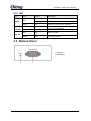
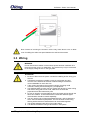
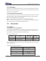
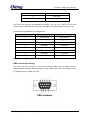
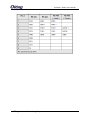
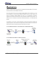
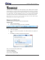
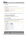
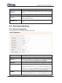
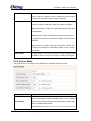
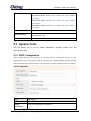
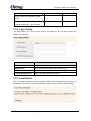
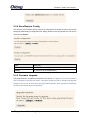
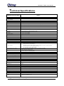
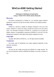
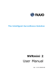
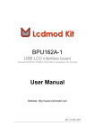
IDS-M311 Industrial Modbus Gateway User Manual Version 1.0 JUN, 2014 www.oring-networking.com IDS-M311 Series User Manual COPYRIGHT NOTICE Copyright © 2014 ORing Industrial Networking Corp. All rights reserved. No part of this publication may be reproduced in any form without the prior written consent of ORing Industrial Networking Corp. TRADEMARKS is a registered trademark of ORing Industrial Networking Corp. All other trademarks belong to their respective owners. REGULATORY COMPLIANCE STATEMENT Product(s) associated with this publication complies/comply with all applicable regulations. Please refer to the Technical Specifications section for more details. WARRANTY ORing warrants that all ORing products are free from defects in material and workmanship for a specified warranty period from the invoice date (5 years for most products). ORing will repair or replace products found by ORing to be defective within this warranty period, with shipment expenses apportioned by ORing and the distributor. This warranty does not cover product modifications or repairs done by persons other than ORing-approved personnel, and this warranty does not apply to ORing products that are misused, abused, improperly installed, or damaged by accidents. Please refer to the Technical Specifications section for the actual warranty period(s) of the product(s) associated with this publication. DISCLAIMER Information in this publication is intended to be accurate. ORing shall not be responsible for its use or infringements on third-parties as a result of its use. There may occasionally be unintentional errors on this publication. ORing reserves the right to revise the contents of this publication without notice. CONTACT INFORMATION ORing Industrial Networking Corp. 3F., NO.542-2, Jhongjheng Rd., Sindian District, New Taipei City 231, Taiwan, R.O.C. Tel: + 886 2 2218 1066 // Fax: + 886 2 2218 1014 Website: www.oring-networking.com Technical Support E-mail: [email protected] Sales Contact E-mail: [email protected] (Headquarters) [email protected] (China) ORing Industrial Networking Corp 1 IDS-M311 Series User Manual Table of Content Getting Started ............................................................................................... 3 1.1 About IDS-M311 ................................................................................................... 3 1.2 Software Features ................................................................................................ 3 1.3 Hardware Specifications ....................................................................................... 3 Hardware Overview ........................................................................................ 4 2.1 Top Panel ............................................................................................................. 4 2.1.1 2.2 Ports and Connectors ....................................................................................... 4 Front Panel ........................................................................................................... 4 2.2.1 2.3 LED .................................................................................................................. 5 Bottom Panel ........................................................................................................ 5 Hardware Installation ..................................................................................... 6 2.4 DIN-rail Installation ............................................................................................... 6 3.2 Wall Mounting ....................................................................................................... 7 3.3 Wiring ................................................................................................................... 8 3.3.1 Grounding ............................................................................................................ 9 3.3.2 Redundant Power Inputs....................................................................................... 9 3.4 Connection ........................................................................................................... 9 3.4.1 Cables .................................................................................................................. 9 Applications ................................................................................................. 12 Management ................................................................................................. 13 5.1 Network Configuration .................................................................................... 14 5.1.1 IP Configuration.............................................................................................. 14 5.2 Port Serial Setting........................................................................................... 15 5.2.1 Serial Configuration ........................................................................................ 15 5.2.2 Service Mode ............................................................................................. 16 5.3 System Tools .................................................................................................. 17 5.3.1 SNTP Configuration ........................................................................................ 17 5.3.2 Login Setting .................................................................................................. 19 5.3.3 Load Default ............................................................................................... 19 5.3.4 Save/Restore Config .................................................................................. 20 5.3.5 Firmware Upgrade...................................................................................... 20 5.3.6 Restart Device............................................................................................ 21 ORing Industrial Networking Corp 2 IDS-M311 Series User Manual Getting Started 1.1 About IDS-M311 IDS-M311 is a 1-port Modbus gateway which converts signals between Modbus TCP and Modbus RTU/ASCII devices. The device is able to support up to 31 RTU/ASCII devices with its serial port, thus can effectively connect a high density of Modbus nodes to the same network. You can use the Web configuration interface to configure multiple devices and set up IDS-M311 operation modes for different application requirements. IDS-M311 supports RS-232/422/485 and provides dual redundant power inputs guarantee a non-stop operation. 1.2 Software Features Operation modes includes RTU Master, RTU Slave, ASCII Master, ASCII Slave Supports up to 16 TCP connections and 32 requests simultaneously Convert between Modbus TCP and Modbus RTU/ASCII Internet communication: PPPoE Update DNS hostname: DDNS Event warning by Syslog, Email, SNMP trap, and beeper Configurable by Web Interface Various Windows O.S. supported: Windows NT/2000/ XP/ 2003/VISTA(32/64bit)/ Windows 7(32/64bit) 1.3 Hardware Specifications Dual DC power inputs 1xRS-232/422/485 software selectable serial port DIN-rail and Wall mount enabled Redundant DC power inputs Operating Temperature: -10 to 60oC Storage Temperature: -40 to 85oC Operating Humidity: 5% to 95%, non-condensing Casing: IP-30 Dimensions: 72(W) x 29.4(D) x 123.4(H) mm (2.83x1.16x4.86 inch.) ORing Industrial Networking Corp 3 IDS-M311 Series User Manual Hardware Overview 2.1 Top Panel 2.1.1 Ports and Connectors The device provides the following ports on the top panel. The Ethernet port on the device use RJ-45 connectors Port Copper port Description 1 x 10/100Base-T(X) port Power connector 1 three-pin dual power connector 1. Terminal block: PWR1 (12 ~ 48V DC) 2. Power jack: PWR2 (12 ~ 48V DC) 3. RJ45 Ethernet Connector 2.2 Front Panel 1. LED for PWR1. 2. LED for PWR2 3. LED for 10/100Base-T(X) Ethernet port 4. LED for serial port ORing Industrial Networking Corp 4 IDS-M311 Series User Manual 2.2.1 LED LED Color Status Description On Power module activated Blinking DHCP servers do not respond properly Green On ETH Green On Power is on and function normally Port running at 100Mbps LNK/ACT Amber On Port running at 10Mbps. Red On Receiving data Green On Transmitting data Red PW1/2 TX / RX 2.3 Bottom Panel 1. Serial port 2. Reset button ORing Industrial Networking Corp 5 IDS-M311 Series User Manual Hardware Installation 2.4 DIN-rail Installation The device comes with a DIN-rail kit to allow you to fasten the device to a DIN-rail in any environments. DIN-rail Kit Measurement (unit = mm) Installing the device on the DIN-rail is easy. First, screw the Din-rail kit onto the back of the device, right in the middle of the back panel. Then slide the device onto a DIN-rail from the Din-rail kit and make sure the device clicks into the rail firmly. ORing Industrial Networking Corp 6 IDS-M311 Series User Manual 3.2 Wall Mounting Besides Din-rail, the device can be fixed to the wall via a wall mount panel, which can be found in the package. Wall-Mount Kit Measurement (unit = mm) To mount the device onto the wall, follow the steps: 1. Attach the wall-mount kit to the back of the device using the three DIN-rail screw holes. 2. Use the device, with wall mount plates attached, as a guide to mark the correct locations of the four screws. 3. Insert screws through the round screw holes (the red arrow as below) on the sides or through the key hole-shaped aperture (the green arrow as below) in the middle of the plate and fasten the screw to the wall with a screwdriver. 4. If the screw goes through the key hole-shaped aperture, slide the device down before tightening the screw. ORing Industrial Networking Corp 7 IDS-M311 Series User Manual Note: Instead of screwing the screws in all the way, leave about 2 mm to allow room for sliding the wall mount panel between the wall and the screws. 3.3 Wiring WARNING Do not disconnect modules or wires unless power has been switched off or the area is known to be non-hazardous. The devices may only be connected to the supply voltage shown on the type plate. ATTENTION 1. Be sure to disconnect the power cord before installing and/or wiring your devices. 2. Calculate the maximum possible current in each power wire and common wire. Observe all electrical codes dictating the maximum current allowable for each wire size. 3. If the current goes above the maximum ratings, the wiring could overheat, causing serious damage to your equipment. 4. Use separate paths to route wiring for power and devices. If power wiring and device wiring paths must cross, make sure the wires are perpendicular at the intersection point. 5. Do not run signal or communications wiring and power wiring through the same wire conduit. To avoid interference, wires with different signal characteristics should be routed separately. 6. You can use the type of signal transmitted through a wire to determine which wires should be kept separate. The rule of thumb is that wiring sharing similar electrical characteristics can be bundled together 7. You should separate input wiring from output wiring 8. It is advised to label the wiring to all devices in the system ORing Industrial Networking Corp 8 IDS-M311 Series User Manual 3.3.1 Grounding Grounding and wire routing help limit the effects of noise due to electromagnetic interference (EMI). Run the ground connection from the ground pin on the power module to the grounding surface prior to connecting devices. 3.3.2 Redundant Power Inputs The device has two sets of power inputs in the form of DC power jack and terminal. The power input connectors are located on the top panel alongside the Ethernet port. Follow the steps below to wire the power input on the terminal block. Step 1: insert the negative/positive wires into the V-/V+ terminals, respectively. Step 2: to keep the wires from pulling loose, use a small flat-blade screwdriver to tighten the wire-clamp screws on the front of the terminal block connector. 3.4 Connection 3.4.1 Cables 10/100BASE-T(X) Pin Assignments The device has a standard Ethernet port. According to the link type, the device uses CAT 3, 4, 5,5e UTP cables to connect to any other network devices (PCs, servers, switches, routers, or hubs). Please refer to the following table for cable specifications. Cable Types and Specifications: Cable Type Max. Length Connector 10BASE-T Cat. 3, 4, 5 100-ohm UTP 100 m (328 ft) RJ-45 100BASE-TX Cat. 5 100-ohm UTP UTP 100 m (328 ft) RJ-45 With 10/100Base-T(X) cables, pins 1 and 2 are used for transmitting data, and pins 3 and 6 are used for receiving data. 10/100 Base-T(X) RJ-45 Pin Assignments : Pin Number Assignment 1 TD+ 2 TD- 3 RD+ 4 Not used 5 Not used ORing Industrial Networking Corp 9 IDS-M311 Series User Manual 6 RD- 7 Not used 8 Not used The device also supports auto MDI/MDI-X operation. You can use a cable to connect the device to a PC. The table below shows the 10/100Base-T(X) MDI and MDI-X port pin outs. 10/100 Base-T(X) MDI/MDI-X Pin Assignments: Pin Number MDI port MDI-X port 1 TD+(transmit) RD+(receive) 2 TD-(transmit) RD-(receive) 3 RD+(receive) TD+(transmit) 4 Not used Not used 5 Not used Not used 6 RD-(receive) TD-(transmit) 7 Not used Not used 8 Not used Not used Note: “+” and “-” signs represent the polarity of the wires that make up each wire pair. DB9 console port wiring The device can be connected to a serial device using a DB9 cable. The DB9 connector supports RS232 / RS422 / RS485 operation modes. Please refer to the following table for the pin assignments of the DB9 connector. ORing Industrial Networking Corp 10 IDS-M311 Series User Manual ORing Industrial Networking Corp 11 IDS-M311 Series User Manual Applications IDS-M311 enables Modbus serial slaves to be integrated with existing Modbus TCP networks and serial masters to access Modbus TCP slaves. Since most modern PLCs and host computers support Modbus TCP over Ethernet, you can use the IDS-M311 to access discrete Modbus RTU/ASCII devices for data collection and control. The IDS-M311 supports Modbus TCP with up to 16 simultaneous connections. Supported serial interfaces include RS-232 and RS-422/485, selectable through software. The serial port can be connected to one RS-232 or RS-422 serial device, or to 32 RS-485 serial devices. The IDS-M311 can be used in several applications, including linking Ethernet masters with multiple serial slaves, serial masters with multiple Ethernet slaves, Modbus TCP masters with ASCII and RTU slaves, and serial master with serial slaves over Internet. Connect Modbus/TCP Master to Serial Modbus/RTU or Modbus/ASCII Slaves Connect Modbus Serial Masters to Modbus/TCP Slaves ORing Industrial Networking Corp 12 IDS-M311 Series User Manual Management The device can be managed via a built-in web server which supports Internet Explorer (Internet Explorer 5.0 or above versions) and other Web browsers such as Chrome. Therefore, you can manage and configure the device easily and remotely. You can also upgrade firmware via a Web browser. The Web management function not only reduces network bandwidth consumption, but also enhances access speed and provides a user-friendly viewing screen. Note: By default, IE5.0 or later version do not allow Java applets to open sockets. You need to modify the browser setting separately in order to enable Java applets for network ports. Management via Web Browser Follow the steps below to manage your device via a Web browser System Login 1. Launch an Internet Explorer. 2. Type http:// and the IP address of the device. Press Enter. 3. A login screen appears. 4. Type in the username and password. The default username and password is admin. 5. Press Enter or click OK, the management page appears. Note: you can use the following default values: IP Address: 192.168.10.1 Subnet Mask: 255.255.255.0 Default Gateway: 192.168.10.254 ORing Industrial Networking Corp 13 IDS-M311 Series User Manual User Name: admin Password: admin After logging in, you will see the information of the device as below. On the left hand side of the management interface shows links to various settings. Clicking on the links will bring you to individual configuration pages. 5.1 Network Configuration This page allows you to configure the network functions of the device. 5.1.1 IP Configuration This page shows the general information of the device. You can assign an IP for the device manually or have the DHCP server assign the IP automatically. Select “Static IP” if you are using a fixed IP address. Click Apply after you complete configuration. Label Description IP Configuration Choose to use a static or DHCP-assigned IP. If you choose ORing Industrial Networking Corp 14 IDS-M311 Series User Manual DHCP, the following fields will gray out. IP Address Netmask Gateway DNS Server 1/2 Enter the IP address that identifies the server on the TCP/IP network Enter a subnet mask for the device. Enter the IP address of the router that provides network access outside the server’s LAN Enter the IP address of the primary and secondary domain name server 5.2 Port Serial Setting 5.2.1 Serial Configuration This page allows you to configure serial port parameters. Label Description Port Alias Enter the COM port number that modem is connected to Interface Choose an interface for your serial device. Available interfaces include RS-232, RS-422, RS-485-2W, and RS-485-4W. Baud Rate Choose a baud rate in the range between 110 bps and 11520 bps Data Bits Choose the number of data bits to transmit. You can configure data bits to be 5, 6, 7, or 8. Data is transmitted as a series of five, six, seven, or eight bits (five and six bit data formats are used rarely for specialized communications equipment). Stop Bits Choose the number of bits used to indicate the end of a byte. You can configure stop bits to be 1 or 1.5(2). If Stop Bits is 1.5, the ORing Industrial Networking Corp 15 IDS-M311 Series User Manual stop bit is transferred for 150% of the normal time used to transfer one bit. Both the computer and the peripheral device must be configured to transmit the same number of stop bits. Parity Chose the method of detecting errors in transmission. Parity control bit modes include None, Odd, Even, Mark, and Space. None means parity checking is not performed and the parity bit is not transmitted. Odd means the number of mark bits in the data is counted, and the parity bit is asserted or unasserted to obtain an odd number of mark bits. Even means the number of mark bits in the data is counted, and the parity bit is asserted or unasserted to obtain an even number of mark bits. Flow Control Choose XOFF to tell the computer to stop sending data or XON to tell the computer to begin sending data again 5.2.2 Service Mode This page allows you to configure the parameters for individual operation modes. Label Description Choose an operation mode for the serial port. You can configure a serial port as Modbus Master or Modbus Slave mode. Available Service Mode options include RTU Slave Mode, RTU Master Mode, ASCII Slave Mode, and ASCII Master Mode. RTU Slave Mode: Modbus TCP masters will control Modbus RTU ORing Industrial Networking Corp 16 IDS-M311 Series User Manual Slaves RTU Master Mode: Modbus RTU masters will control Modbus TCP slaves ASCII Slave Mode: Modbus TCP master will control Modbus ASCII Slaves ASCII Master Mode: Modbus RTU masters will control Modbus TCP slaves TCP Server Port Enter the TCP server port number The maximum number of simultaneous connections supported. Max Connection The maximum is 32. Connection Timeout Set a value for connection timeout. The unit is in seconds. 5.3 System Tools This link allows you to set up system parameters, including system time and authentication data. 5.3.1 SNTP Configuration SNTP (Simple Network Time Protocol) is a protocol able to synchronize the time on your system to the clock on the Internet. It will synchronize your computer system time with a server that has already been synchronized by a source such as a radio, satellite receiver or modem. Label Description Device Name Enter the model name of the device Device Enter the description for the device Description ORing Industrial Networking Corp 17 IDS-M311 Series User Manual SNTP Enable or disable SNTP function Time Zone Choose the time zone according to the location of the device Local Time Set up the local time Time Server Enter the address of the time server The following table lists different location time zones for your reference. Local Time Zone Conversion from UTC Time at 12:00 UTC November Time Zone - 1 hour 11 am Oscar Time Zone -2 hours 10 am ADT - Atlantic Daylight -3 hours 9 am AST - Atlantic Standard EDT - Eastern -4 hours 8 am -5 hours 7 am -6 hours 6 am -7 hours 5 am -8 hours 4 am ALA - Alaskan Standard -9 hours 3 am HAW - Hawaiian Standard -10 hours 2 am Nome, Alaska -11 hours 1 am CET - Central European FWT - French +1 hour 1 pm EET - Eastern European, USSR Zone 1 +2 hours 2 pm BT - Baghdad, USSR Zone 2 +3 hours 3 pm ZP4 - USSR Zone 3 +4 hours 4 pm ZP5 - USSR Zone 4 +5 hours 5 pm ZP6 - USSR Zone 5 +6 hours 6 pm WAST - West Australian Standard +7 hours 7 pm CCT - China Coast, USSR Zone 7 +8 hours 8 pm JST - Japan Standard, USSR Zone 8 +9 hours 9 pm Daylight EST - Eastern Standard CDT - Central Daylight CST - Central Standard MDT - Mountain Daylight MST - Mountain Standard PDT - Pacific Daylight PST - Pacific Standard ADT - Alaskan Daylight Winter MET - Middle European MEWT Middle European Winter SWT - Swedish Winter ORing Industrial Networking Corp 18 IDS-M311 Series User Manual EAST - East Australian +10 hours 10 pm +12 hours Midnight Standard GST Guam Standard, USSR Zone 9 IDLE - International Date Line NZST - New Zealand Standard NZT - New Zealand 5.3.2 Login Setting This page allows you to set up login account and password. You can also change your password in this page. Label Description Login Name Enter a user name for login Old Password Enter the existing password that is used to log in New Password Enter a new password that will be used to log in Confirm New Password Retype the new password to confirm 5.3.3 Load Default You can reset the system to its factory settings. Simply click on Reset which will bring you to the Reboot button. Once the device is restarted, it will be restore to factory default settings. ORing Industrial Networking Corp 19 IDS-M311 Series User Manual 5.3.4 Save/Restore Config You can save current values from the device as a backup file or restore the device to previous settings by downloading a configuration file. Simply browse to the configuration file you want to use and click Restore. Label Description Restore Click to restore the configurations. Backup Click to back up the configurations. 5.3.5 Firmware Upgrade This page allows you to update the firmware of the device. To upgrade, you need a firmware files correspond to this Device model. It will take several minutes to upload and upgrade firmware. Do not turn of the power during firmware upgrade. After upgrade is completed, the device will reboot and be revalidated. ORing Industrial Networking Corp 20 IDS-M311 Series User Manual 5.3.6 Restart Device You can reboot the device by click Reboot button. ORing Industrial Networking Corp 21 IDS-M311 Series User Manual Technical Specifications ORing Device Server Model IDS-M311 Physical Ports 10/100 Base-T(X) Ports in RJ45 1 Auto MDI/MDIX Serial Ports Connector DB9(male) x 1 Operation Mode RS232 / RS422 / 4(2)-Wire RS485. Serial Baud Rate 110 bps to 460.8 Kbps Data Bits 5, 6, 7, 8 Parity odd, even, none, mark, space Stop Bits 1, 1.5, 2 RS-232 TxD, RxD, RTS, CTS, DTR, DSR, DCD, RI, GND RS-422 Tx+,Tx-, Rx+, Rx-,GND RS-485 (4-wire) Tx+,Tx-, Rx+, Rx-,GND RS-485 (2-wire) Data+, Data-,GND Flow Control XON/XOFF, RTS/CTS, DTR/DSR Which can be configured by Web interface Network Protocol Protocol ICMP, IP, TCP, UDP, DHCP, BOOTP, DNS, SNMP V1/V2c, HTTPS, SMTP, DDNS, PPPoE, Modbus TCP LED indicators PWR 1(2) / Ready: Red On: Power is on and booting up. Power indicator Red Blinking: Indicates an IP conflict, or DHCP or BOOTP server did not respond properly. Green On: Power is on and functioning Normally. Green Blinking: Located by Administrator. 10/100TX RJ45 port indicator Serial TX / RX LEDs: Green for port Link/Act at 100Mbps. Amber for port Link/Act at 10Mbps. Red: Serial port is receiving data Green: Serial port is transmitting data Power Redundant Input power Dual DC inputs. 12-48VDC on 3-pin terminal block and power jack Power consumption (Typ.) 4 Watts Overload current protection Present Reverse polarity protection Present on terminal block Physical Characteristic Enclosure IP-30 Dimension (W x D x H) 72(W)x29.4(D)x123.4(H) mm (2.83x1.16x4.86 inch.) Weight (g) 294 Environmental Storage Temperature -40 to 85oC (-40 to 185oF) Operating Temperature -10 to 60oC (14 to 140oF) Operating Humidity 5% to 95% Non-condensing Regulatory approvals EMI EMS FCC Part 15, CISPR (EN55022) class A EN61000-4-2 (ESD), EN61000-4-3 (RS), EN61000-4-4 (EFT), EN61000-4-5 (Surge), EN61000-4-6 (CS), EN61000-4-8, EN61000-4-11 ORing Industrial Networking Corp 22 IDS-M311 Series User Manual Shock IEC60068-2-27 Free Fall IEC60068-2-32 Vibration IEC60068-2-6 Safety EN60950-1 Warranty 5 years ORing Industrial Networking Corp 23