1
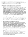
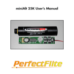
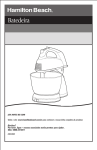
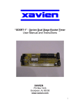
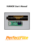
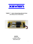
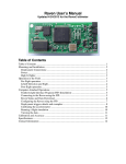
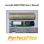
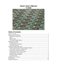
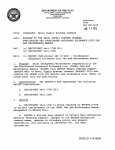
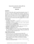
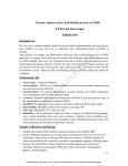
microTimer2 / miniTimer3
User’s Manual
Miniature digital timers for auxillary
motor ignition or recovery deployment.
microTimer2
15 Pray Street
Amherst, MA 01002
Voice (413) 549-3444
FAX (413) 549-1548
miniTimer3
URL: www.perfectflite.com
Sales: [email protected]
Support: [email protected]
Congratulations on the purchase of your new staging/ejection
timer. Please read these instructions carefully before attempting to
use the timer to insure safe and successful operation.
These timers can be used in a number of applications:
o Ignition of upper stages in multi-stage rockets.
The first stage (booster) motor is ignited conventionally on the
pad. The timer is triggered as the rocket rises, beginning its
timing cycle. After the user-programmed interval (coincident
with booster motor burnout), power is applied to the next
stage’s ignition system. Electronic ignition of the upper stage
allows for staging of composite propellant motors and the use
of longer booster sections which are not generally suitable for
conventional “burn-through” (gap) staging techniques.
o
Airstart ignition of auxillary motors in clustered rockets.
The main motor is ignited conventionally on the pad, and the
timer is triggered as the rocket lifts off. After the programmed
time interval additional motors in the cluster are ignited by the
timer, providing an extended burn time for greater altitude.
o
Electronic deployment of recovery devices.
The timer is activated at liftoff. After the programmed time
interval power is provided to an ejection charge to deploy the
parachute. The timer provides a wider range of precise,
repeatable delay times than that which is available with the
motor’s built-in delay. Keeping an assortment of motors with
different delay times is no longer necessary. Since the motor
ejection charge is not used, the problem of delay “blow-by”
causing premature ejection is eliminated.
o
Redundant deployment of recovery devices.
An altimeter or accelerometer provides the primary recovery
system deployment, and the timer ignites an additional
ejection charge several seconds “late” as a backup in case of
altimeter/accelerometer failure.
Features
o
o
o
o
o
o
o
o
Easy to set delay time
The delay time can be quickly set in the field and is reported
numerically for confirmation after setup.
Audible or visual continuity indication
The continuity of the igniter circuit is checked and reported
while awaiting launch. The miniTimer uses a built-in beeper,
and the microTimer uses a space-saving LED. An external
beeper can be added to the microTimer.
Post flight locater siren
The miniTimer’s beeper produces a warbling “hi-low” siren
tone after timeout to aid in locating your rocket. The optional
external beeper for the microTimer also performs this function.
Automatic trigger sense configuration
The timer determines whether a normally-closed trigger switch
(e.g. breakwire) or normally-open trigger (e.g. G switch) is
connected and configures itself accordingly.
False trigger filtering
The trigger condition must be met for 0.5 second for the timing
cycle to initiate. This eliminates false activations due to trigger
switch glitches or momentary activation of a G switch.
High current capability
The timers can switch very high current levels (refer to the
specifications section at the end of this manual for exact
numbers). This allows the use of multiple parallel-connected
igniters for clustered airstarts.
High accuracy, nonvolatile setting
The user-programmed time delay is derived digitally for
repeatable, drift-free performance. The delay setting is stored
in nonvolatile EEPROM and is retained even with power off.
Small size, light weight
Allows for easy installation in virtually any application.
Mounting hardware is supplied with the miniTimer.
Operation
When power is applied to the timer it will enter one of two modes
depending on the state of the “program” button. If the button is
held down when the timer is powered up, it will enter “program”
mode to enable the setting of the delay time. If the button is not
held down on powerup, normal timer mode will commence. The
program button is only sampled at powerup, so pushing the button
at any other time will have no effect on the operation of the timer.
Program Button
Program Mode (setting the delay)
If the timer is powered up while the program button is depressed, a
confirmation tone will be heard from the beeper (the microTimer’s
LED glows instead). Releasing the program button will stop the
tone and prepare the timer for programming. The time delay is
then set by holding the button down for a time equal to the desired
delay. The beeper will produce a tone while the button is held
down to assist in setting the delay. When the button is released, the
beeper will sound a long confirmation tone followed by a sequence
of beeps representing the saved time delay in tenths of a second. If
the delay is set to 1.6 seconds, the beeper will beep out a single
beep (1), followed by six beeps (6), or 16 tenths of a second (1.6
seconds). The digit zero is represented by ten beeps, and leading
(non-significant) zeroes are suppressed. If the programming button
is held down for less than 0.6 seconds (the minimum time delay)
then the actual saved delay will default to 0.6 seconds. Note: The
delay setting is from first trigger sense to output activation. You do not
have to adjust for the 0.5 second trigger safety threshold.
Normal Operation Mode
If the program button is not depressed when the timer is powered
up, normal operation mode will be selected. A long tone will
sound, followed by a sequence of beeps reporting the preset time
delay as described earlier. The beeper then emits a high/low/
high/low tone sequence as it looks at the trigger input to detect the
“normal” (untriggered) state. If the trigger switch is open during
this period (as in a G-switch trigger), the continuity check will
report using a high pitched tone. If the trigger switch is closed (as
in a breakwire), the continuity check will report using a low pitched
tone. This feature allows the user to confirm that the trigger circuit
is configured as expected prior to flight. Note: The microTimer’s
LED glows but will not differentiate normally closed vs. normally open.
The continuity check tone will then be emitted until the timer is
triggered. In order to generate a valid launch detect, the trigger
condition must be met for a period of 0.5 second without interruption. This prevents wind or vibration induced glitches from
prematurely initiating the timing cycle. When a valid launch
condition is detected, the timer will wait out the remainder of the
time delay before applying power to the igniter circuit. The igniter
circuit is powered on for a period of approximately one second, and
then the beeper sounds the post-flight siren.
Triggering Options
The timer can be triggered by
a normally closed (shorted) or
normally open (unshorted)
circuit connecting the two
“Trigger” connection pads. An
example of a normally closed
circuit is the “breakwire”,
which is simply a thin wire
connecting these terminals
together, with a stronger piece
of wire looped around the
Internal wiring to
timer "T" terminals
Connection
screws
Thin (32-36 guage)
break-wire
Thick anchor wire
(secure bottom
end to ground)
breakwire and fixed to the ground. When the rocket leaves the pad,
tension from the heavier wire snaps the breakwire, opening the
normally closed circuit and triggering the timer.
A similar triggering method involves the use of a pull-pin on a cord
staked to the ground, which is then inserted into a switching
mechanism such as the normally open contacts of a miniature 1/8”
phone jack. When the pin is inserted into the jack, it closes the
switch contacts, creating a normally closed condition. When the
rocket leaves the pad, the pin is pulled, opening the contacts and
triggering the timer.
The triggering circuit can be made completely self-contained (no
external connections) with the addition of a “G switch”. This
device senses acceleration along its longitudinal axis and closes its
contacts when the acceleration exceeds a specific threshold (a 2G
threshold is common in this application). When the rocket experiences 0.5 second of acceleration in excess of this rating, the timer
will be triggered. Make sure that G switches are oriented in the
proper direction–one end (as specified by the manufacturer) will
have to point in the direction of travel. The miniTimer is available
with or without a pre-installed G switch. The G switch equipped
model (MT3G) has “UP” and “AFT END” designations printed on
the board to specify mounting orientation.
miniTimer with G switch
installed on trigger pads
trigger connection pads
Installation and Connections
The miniTimer should be mounted using the supplied 4-40 hex
standoffs and hardware. The smaller microTimer can be glued in
place or restrained inside a piece of foam rubber. Make sure that
your mounting scheme does not preclude access to the programming switch. If you are using a G switch trigger, make sure that the
G switch is facing in the proper orientaion.
The microTimer has solder pads for battery, igniter, and trigger
connections. A smaller set of pads adjacent to the “program”
button is provided for the connection of an optional piezoelectric
speaker. Use care when soldering to the board to prevent solder
bridges or damage to the surface mount components.
The miniTimer uses screw-down terminal blocks for battery and
igniter connections. Loosen the screw, insert the wire, and tighten
the screw down. If you are using stranded wire, make sure that the
individual strands are twisted tightly together so that they don’t
“peel back” and short to adjacent conductors. It’s a good idea to
pull on the wires after they are clamped to insure that they are
captured properly. The miniTimer without G switch (MT3T) has
solder pads for connecting an external trigger source. Use care
when soldering to the board to prevent solder bridges or damage to
the surface mount components.
*** Important ***
Observe proper polarity (+/-) when connecting the battery!
If reverse voltage is applied, the switching FET’s body diode will
conduct, resulting in immediate firing of any attached igniters.
If power is applied before attaching igniters (as is recommended in
the operational checklist), proper polarity will be confirmed by the
power-up beep (or LED) sequence. Improper polarity will result in
silence or no LED glow.
An external power switch can be inserted in the battery “+” wire.
Make sure that it is capable of carrying the expected peak current of
your igniter circuit. Since the timer actually switches the igniter
current on and off, the power switch does not need to be rated for
switching full load, just carrying it.
Igniter
Power switch
Trigger switch
(MT3T only)
Trigger switch
Igniter
Battery
Try to keep the wiring lengths to a minimum to reduce voltage
drops due to wiring resistance. The battery should be mounted as
far forward as possible to improve the CP/CG relationship for best
stability. Make sure that the timer, battery, and wiring do not
interfere with the proper deployment of the recovery devices, and
keep the timer out of the path of corrosive ejection gasses.
Always test a new installation before launching. Set up the timer
normally, substituting a dummy load such as a light bulb for the
igniter. Run through the checklist and confirm that the delay is as
desired and that the bulb comes on at the end of the time interval.
Using an igniter of the type that will be used in the real application
(but not installed in an engine or ejection charge) will confirm that
the battery has enough power to fire the igniter. G switch equipped
timers can be activated by swinging the rocket in a circle with the
nosecone facing straight inward to simulate acceleration.
Igniter Selection
Recovery Deployment Applications
When using the timer for recovery system deployment, the best
choices for ejection charge igniters are DaveyFire N28B or Oxral
ematches or Christmas tree bulb based charges (PerfectFlite ECK6).
These are low current devices that provide a short burst of heat to
ignite the easily combustible black powder ejection charge.
Auxillary Motor Ignition
When using the timer to ignite sustainer or airstart motors, longer
burning, hotter igniters should be employed. Normal Estes igniters
can be used in the smaller black powder motors. Composite
motors work well with the DaveyFire N28F ematch (dip the head in
pyrogen for extra reliability) or igniters made by dipping leadwires
in conductive primer and auxillary pyrogen. The DaveyFire match
heads are too large to fit in the nozzle throat of smaller composite
motors, and therefore are generally used only in 38mm or larger
motor sizes. Aerotech FirstFire igniters can also be used, but will
require a more powerful (and therefore larger) battery.
Battery Guidelines
Igniters are basically small electric heaters that consume a relatively
large amount of power (compared to the timer itself). The battery
must be able to supply enough power to fire the igniter reliably and
consistently. The timers incorporate brown-out protection so that
the battery voltage can drop to zero during firing without affecting
operation of the timer. In general, if the battery you use can fire the
igniter when connected directly, it will work with the timer as well.
Make sure that the battery’s voltage and expected current do not
exceed the specifications listed at the end of this manual.
Calculating Igniter Current Requirements
The current demand of a particular igniter/battery combination can
be determined relatively easily using Ohm’s Law, which states that
current (I) is equal to voltage (V) divided by resistance (R). Igniter
resistance is frequently specified by the igniter manufacturer, and
can also be measured with a multimeter set to a low resistance
range. Some representative igniter resistances are listed below.
The nominal open-circuit voltage of the battery is easily determined, but we must remember that the voltage will drop under
load due to the battery’s internal resistance. If you try to draw 20
amps from a 9V battery, the battery’s voltage will drop to next to
nothing. NiCad batteries tend to have the lowest internal resistance
and keep their voltage up well under load. Nickel Metal Hydride
(NiMH) batteries have high internal resistance and should not be
used in this application.
Use Ohm’s Law (I=E/R) to determine the current demand of the
chosen igniter. If you are using multiple igniters in parallel (for
clustered applications) the current demand of each igniter must be
multiplied by the number of igniters used. Once the total current
draw is determined (not to exceed the current rating of the timer),
an appropriate battery can be specified. Choose a battery that will
be able to supply the required current while maintaining the
necessary voltage. Note that even the “low current” ematches
draw a lot of current at higher voltages due to their low resistance.
Common 9 volt batteries are not well suited for this application!
Igniter Type
Resistance
Firing Current*
DaveyFire..............................1.6Ω ............................1.0A (N28F)
Oxral......................................2.0Ω ............................0.5A
Estes.......................................0.6Ω ............................2.0A
FirstFire .................................0.8 Ω ............................4.0A
Dipped...................................5Ω - 15Ω .....................varies (~0.5A to 2A)
* Higher applied current will result in faster ignition and shorter duration of current flow.
Battery Type
Nom. V
V@2A
V@5A
V@10A V@20A
9V alkaline .....................9.3V ........3.1V ........–––– ........–––– ........––––
“9V” 7 cell NiCad .........9.1V ........4.5V ........0.6V ........–––– ........––––
“9V” N6PT NiCad ........7.7V ........6.9V ........5.6V ........2.9V ........0.8V
4 cell 2/3AA NiCad......5.4V ........5.1V ........4.4V ........3.3V ........1.6V
4 cell 2/3A NiCad.........5.4V ........5.1V ........4.7V ........4.0V ........2.8V
6 cell sub-C NiCad........8.1V ........7.9V ........7.6V ........7.1V ........6.2V
Igniter Fabrication
Dipped igniters can be created easily in the following manner. The
resulting igniters will fire on a standard 9V NiCad battery, drawing
less than 2 amps of current. You should test-fire a number of
igniters in a fireproof, well-ventilated area to perfect your fabrication technique before relying on them for use in flight.
A.
B.
Prepare the leadwires. For larger nozzle motors, standard 24
gauge solid conductor twinlead is inexpensive and durable.
For smaller throat motors (E11, E15, and even smaller) the
best choice is 30 gauge Kynar insulated wire-wrap wire. The
wire-wrap wire needs to be twisted into a two-conductor
cable before proceeding. This is easily done by chucking two
lengths of the wire in an electric drill and twisting until a
reasonably tight twist is created. Make up 10 or 20 feet at a
time, and cut it into ~12” long sections for igniters.
Strip approximately 1/32”-1/16” insulation from the active
end of the leadwire (the end that will be dipped) and 1/2”
insulation from the other end (for connection to the timer).
Dip the active end of the leadwire in conductive primer
(FireFox ELV Conductive Primer or similar). The primer
should be stirred thoroughly before each dipping session,
and thinned with acetone to achieve a thick syrup-like
consistency. You don’t need much primer, a small bead
covering the stripped ends is fine. If you use too much
primer, it will ignite with a “pop” when fired, which can
blow the second dip of pyrogen off without igniting it.
After dipping the leads in primer, allow the primer coat to
dry for several hours before proceeding. When dry, the
igniter resistance (measured between the 1/2” stripped lead
ends) should be in the range of 5Ω to 20Ω. If the resistance is
out of range, cut off the dipped end and try again. This
shouldn’t happen often, achieving a good primer dip isn’t
hard.
C.
Dip the primed end in pyrogen (FireFox PyroMag Pyrogen
or similar). The pyrogen should be stirred and thinned as
with the primer (if it becomes lumpy, try adding a bit of
Methyl Ethyl Ketone to dissolve the lumps). You will want to
adjust the consistency of the pyrogen to match the desired
application -- narrow igniters for smaller motors should be
dipped using thinner pyrogen, and bigger igniters will be
created with a thicker consistency. Dip the leads to a depth
of approximately 1”, wiggling the lead as you withdraw it
from the pyrogen to keep a large lump from forming on the
end. Set the dipped igniters aside to dry overnight.
Making dipped igniters
Cautions
• Do not connect or install any igniters into rocket engines until
rocket is out of the prep area and on the pad.
• When retrieving a rocket that did not fire all of its motors, remove
the igniters from any live motors before handling or transporting
the rocket.
• Do not touch circuit board traces or components or allow metallic
objects to touch them when the timer is powered on. This could
cause damage to your timer or lead to premature ejection charge
deployment or motor ignition.
• Exercise caution when handling live ejection charges - they
should be considered to be explosive devices and can cause
injury or damage if handled improperly.
• Do not allow the timer to get wet. Only operate the timer within
the environmental limits listed in the specifications section.
• Check battery voltage and polarity before connecting to the timer.
• Always follow proper operational sequencing as listed in
preflight checklist.
Operational Checklist
❏ Insure that power is OFF or battery is disconnected.
❏ Connect external breakwire or install pull-pin as necessary, or
confirm that G switch or other internal trigger mechanism is
connected properly.
❏ Turn power switch ON. Observe proper powerup reporting of
time delay setting. This will also confirm proper battery connection and polarity. Turn power switch OFF.
❏ Connect igniter or ejection system to igniter leads from timer.
❏ Turn power switch ON. Wait for the powerup beep sequence to
finish and verify that the proper continuity is present.
❏ Launch!
Specifications
microTimer 2
dimensions: 0.9”L x 0.7”W x 0.35”T
weight: 3.5 grams
operating voltage: 4.8V to 10.5V
(3.0V to 4.8V at half current rating)
operating current: 1.0 ma no continuity, 3.0 ma w/cont.
1 second firing current: 9.4 amperes
10 ms firing current: 21.8 amperes
1 ms firing current: 39.5 amperes
continuity check current: 75µa/V
trigger: normally-open or normally-closed
timing range: 0.6 to 6553.5 seconds in 0.1 second steps
timing accuracy: +/- 3% typical
operating temperature: 0°C to 70°C
miniTimer 3
dimensions: 1.5”L x 0.9”W x 0.5”T
weight: 7 grams
operating voltage: 4.8V to 10.5V
(3.0V to 4.8V at half current rating)
operating current: 1.0 ma no continuity, 3.0 ma w/cont.
1 second firing current: 33.9 amperes
10 ms firing current: 64.5 amperes
1 ms firing current: 97.6 amperes
continuity check current: 75µa/V
trigger: normally-open or normally-closed
timing range: 0.6 to 6553.5 seconds in 0.1 second steps
timing accuracy: +/- 3% typical
operating temperature: 0°C to 70°C
Igniter Sources
Estes Industries. ............................................................ EST2301 Igniter
1295 H Street
Penrose, CO 81240
FireFox Enterprises................................................. ELV, Pyromag (kits)
P.O. Box 5366
11612 N. Nelson
Pocatello, ID 83202
(208) 237-1976
http://www.firefox-fx.com
Luna Tech ......................................................................................... Oxral
148 Moon Drive
Owens Cross Roads, AL 35763
(256) 725-4224
http://www.pyropak.com
Daveyfire.............................................................................. N28B, N28F
7311 Greenhaven Drive, Suite 100
Sacremento, CA 95831-3572
(916) 391-2674
http://www.daveyfire.com/html/electricinitiation.htm
Quickburst ............................................................................. Frog series
http://www.quickburst.net
Countdown Hobbies (dealer)
7 P.T.Barnum Sq.
Bethel, CT 06801-1838
(203)790-9010
http://www.countdownhobbies.com
Magnum Rockets (dealer)
P.O. Box 124
Mechanicsburg, OH 43044
(937) 834-3306
http://www.magnumrockets.com
Warranty
All assembled Perfectflite products include a full three year/36
month warranty against defects in parts and workmanship. All
Perfectflite kits include a full three year/36 month warranty against
defects in factory-supplied parts. Should your Perfectflite product
fail during this period, call or email our Customer Service department for an RMA number and information about returning your
product. The warranty applies to the timer only, and does not
cover the rocket, motor, or other equipment. This warranty does
not cover damage due to misuse, abuse, alteration, or operation
outside of the recommended operating conditions included with
your product.
Liability
Due care has been employed in the design and construction of this
product so as to minimize the dangers inherent in its use. As the
installation, setup, preparation, maintenance, and use of this
equipment is beyond the control of the manufacturer, the purchaser
and user accept sole responsibility for the safe and proper use of
this product. The principals, employees, and vendors of the
manufacturer shall not be held liable for any damage or claims
resulting from any application of this product. If the purchaser and
user are not confident in their ability to use the product in a safe
manner it should be returned to the point of purchase immediately.
Any use of this product signifies acceptance of the above terms by
the purchaser and user.