1
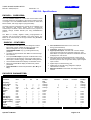
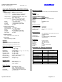
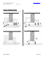
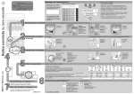
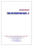
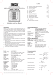
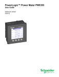
THREE PHASE POWER METER Ref No: m22/om/101 Issue No: 01 masibus User’s Manual PM-2130 THREE PHASE POWER METER Masibus Automation & Instrumentation Pvt. Ltd. B/30, GIDC Electronics Estate, Sector-25, Gandhinagar-382044, Gujarat, India Ph: 91-079-23287275 -- 79 Fax: 91-079-23287281/82 Email: [email protected] Web: www.masibus.com Operator’s Manual Page 1 of 14 THREE PHASE POWER METER Ref No: m22/om/101 Issue No: 01 masibus PM2130 - Contents • Specifications Guide.......................................................................................................3 o Overview ..................................................................................................................3 o Features ...................................................................................................................3 o Parameters...............................................................................................................3 o Technical Specification .............................................................................................4 o Wiring Details ...........................................................................................................5 o Mechanical dimensions detail ...................................................................................6 • Operation Guide ..............................................................................................................7 o Key operation ...........................................................................................................7 o Program Mode Operation .........................................................................................7 o Calibration Procedure...............................................................................................10 • Serial Guide .....................................................................................................................11 o Parameters for 3-ph 4-wire operation – Real Data type ............................................11 o Parameters for 3-ph 3-wire operation – Real Data type ............................................12 o Parameters for 3-ph 4-wire operation – Long Data type............................................13 o Parameters for 3-ph 3-wire operation – Long Data type............................................14 Operator’s Manual Page 2 of 14 THREE PHASE POWER METER Ref No: m22/om/101 masibus Issue No: 01 PM2130 - Specifications PM2130 – OVERVIEW: The 2130 POWER METER is a solid state Power Meter Which accurately measures all quantities of the supply including all types of energies. The 2130 POWER METER is based on ASIC and Microcontroller, with a high degree of programmability. The Meter has been programmed to operate as an intelligent front end measuring and storing device and to communicate continuously to a Master, all the data relevant for the purpose of SCADA, through isolated RS-485 port using MODBUS-RTU protocol. The Meter is normally supplied readily pre-programmed for operation and can be directly installed in the usual manner. The Meter can be read manually or through a Master using MODBUSRTU Protocol PM2130 – FEATURES: The Hardware of the Meter has been designed to make it light weight, rugged, reliable and safe for the user. The Meter is designed so as to provide ACCESS TO AUTHORISED USERS only, by providing data security password. The Meter is self-powered & uses SMPS of Universal range 80 to 550V AC Front panel LED Output for purpose of calibration/Accuracy measurement of selected type of energy like: KWh-Import, KWh-Export, KVARh-Lagging, and KVARh-Leading & KVAh 52 Parameters Measurement display on selectable screen Meter has 4 x 16 LCD to display simultaneously various parameters AUTO-SCALING for measured parameters. (Kilo, Mega & Giga) Four Quadrant Measurement for PF, Power and Energy.(Active-Reactive) Calibration: Digital by front panel keys Digital Input & Output: The Meter has one Pulse Output, which gives Pulse train as per selected energy type. Also Meter takes one Input from Outside and measured value will be displayed on LCD screen Meter is also having Relay output feature in which relay is energized after the set value fixed by user. The digital input feature is optional. User can get either Relay output or digital input at a time. Digital output for selected energy unit Digital input for external energy integration, display & retransmission in RS485 Maximum Demand for both block and sliding window method PM2130’S PARAMETERS: 3 Phase 4 Wire Parameter Unit Frequency Power Factor Vrms (L-N) Irms Vrms (L-L) Ineutral Watt Var VA KWh-Import KWh-Export KVARh-Lagging KVARh-Leading KVAh Output Relay / Input Hz PF Volt Amp Volt Amp Watt Var VA KWh KWh KVARh KVARh KVAh KWh Kw/Kwh Operator’s Manual P1 P2 P3 √ √ √ 1&2 √ √ √ 2&3 √ √ √ 3&1 √ √ √ √ √ √ √ √ √ √ √ √ √ √ √ √ √ √ √ √ √ √ √ √ 3 Phase 3 Wire Tot/Sys/ Avg System Average Average Average System Total Total Total Total Total Total Total Total √ √ P1 & P2 √ √ P1 √ √ √ √ √ √ √ √ P1 & P3 √ P2 P3 & P2 √ √ P3 √ √ √ √ √ √ √ √ Page 3 of 14 Tot/Sys/ Avg System Average Average Average Total Total Total Total Total Total Total Total √ √ THREE PHASE POWER METER Ref No: m22/om/101 masibus Issue No: 01 PM 2130 TECHNICAL SPECIFICATION: Input Nominal Voltage Input Direct voltage : Between 57.8V and 550V Voltage ranges : For 3ph4w 63.5/110V, 69.3/120V, 120/208V, 220/380V, 230/400V, 240/415V, 275/476V Voltage ranges : For 3ph3w 110V, 120V, 380V, 400V, 415V, 440V, 476V Accuracy Range : 50% – 115% of nominal voltage [For 63.5/110V and 69.3/120V, 63% – 115% of Nominal Voltage] Burden : < 2.5 VA per phase Overload : 1.2x Nominal (Continuous) PT Ratio : 1 to 9999.999 Programmable Wire gauge : 12 AWG Nominal Input Current Nominal Current : 1 or 5 Amp. Accuracy Range : 5% – 120% nominal Burden : < 0.5 VA per phase Overload : 20.0 Amp Max. (Continuous) CT Ratio : 1 to 9999.999 Programmable Wire gauge : 12 AWG Maximum Demand Method Burden Less than 5 VA Communication Output Serial port Baud rate Start bit Stop bit Protocol Isolation : RS485 Multidrop : Selectable. 4800/9600/19200 :1 :1 : MODBUS – RTU : 2KV Environmental Working temperature Storage temperature Temperature Coeff Relative humidity Warm up time : 0 to 55 ºC : -10 to 70 ºC : IS-13779 : 30 - 95% non-condensate : 5 min Miscellaneous Display Starting current 0.4% of nominal Current. (Class 1.0) : block or sliding methods programmable Update Rate Sensing Method Frequency 50Hz / 60Hz range ± 5.0Hz : 4X16 Backlight LCD module with 4.75mm Character height : 320ms : True RMS sensing on all channels (Simultaneous) Enclosure System Single Phase 3 phase 3 wire balanced-unbalanced load 3 phase 4 wire balanced-unbalanced load Accuracy: (Class 1) [Given Accuracy is for PF: 0.5Lag-1.0-0.8Lead] Volt Current Frequency Power Factor Active Power Reactive Power Apparent Power Active Energy Reactive Energy Apparent Energy Max Demand : 1% rdg ±1 dgt. : 1% rdg ±2 dgts. : 0.1Hz ±1 dgt. : 1% rdg ±2 dgts (0.5 Lag - 1.0 - 0.8 Lead) : 1% rdg ±2 dgts. : 2% rdg ±2 dgts. : 1% rdg ±2 dgts. : Class 1.0 (IS 13779/IEC 1036) : Class 2.0 (IEC 1268) : Cass 1.0 : 1% rdg ±2 dgts Output Relay Type Rating : Watt/VAR/VA - SPNO : 250V, 2A (AC) : ±30V, 2A (DC) Mounting Cut-Out Enclosure Material Accessory Weight : Panel mounting : 90 mm x 90 mm : 96 x 96 x 74.4 mm : ABS : 2 Panel mount clamps : 0.5 Kg Resolution for Energy parameters Display Format Unit X.XXXX K Last Digit Resolution 0.1 W XX.XXXX K 0.1 W XXX.XXXX K 0.1 W X.XXXXXX M 1W XX.XXXXX M 10 W XXX.XXXX M 100 W X.XXXXXX G 1 KW XX.XXXXX G 10 KW XXX.XXXX G 100 KW Pulse Output Type Rating Pulse Rate Pulse duration Operator’s Manual : Wh/VARh/Vah - SPNO : 200V, 100mA, Resistive (AC) : ±200V, 100mA, Resistive (DC) : 1 to 9999 pulses per selected type : 80 mSec ± 10% Page 4 of 14 THREE PHASE POWER METER Ref No: m22/om/101 Issue No: 01 masibus PM2130 – WIRING DETAILS: The connections have to be made as suggested in the diagram. 3 PT – 3 CT Configuration: (For 3 Phase 4 Wire Supply) 2 PT – 2 CT Configuration: (For 3 Phase 3 Wire Supply) Direct Connection Configuration: (For 3 Phase 4 Wire Supply) 1 PT – 1 CT Configuration: (For single Phase Supply) Operator’s Manual Page 5 of 14 THREE PHASE POWER METER Ref No: m22/om/101 Issue No: 01 masibus PM2130 – Mechanical Dimension Detail: (All Dimensions are in mm.) Notes: Before installing the meter, please go through…. 1. 2. 3. 4. 5. 6. 7. 8. 9. 10. 11. 12. 13. 14. 15. Confirm the connection configuration Confirm that all energy parameters are going to start from zero, if not, make them zero. Apply Proper CT – PT Ratio as per requirement. Select Energy type for LED Blinking as per your requirement. Confirm that Meter is calibrated. For Serial communication, MODBUS-RTU, RS485, you will get real/long data from measurement. Factory set Password to access the Program mode is 0001. Some parameters in configuration are only for factory purposes so please don’t disturb these parameters like Vrated, Irated & System. For 3p3w system, Display Menu will be changed and for modbus communication, follow the address map for 3p3w.Program mode will be same. For Front Blinking LED, select energy type (i.e.-import/KWh-export/KVARh-lag/KVARh-lead /KVAh/MWh-Import/MWh-Export/MVARh-Lag/MVARhLead/MVAh) as per your requirement using Program mode, from OUTPUT and set the value of constant. But here you can get maximum output pulse frequency (& LED Blinking rate) up to 320 ms.so whenever you are using this feature, you should set value of Meter-Constant such a way so it will not cross the limit of 320 ms pulse frequency. For Digital Input Feature, you have to program value of constant – IN1/Unit and for Unit you can select Kilo or Mega. When data type selected for modbus is LONG, Total apparent Energy will overflow from 200GVAhr the meter will auto reset all energy parameter. This includes Active import and export energy, Reactive lead and lag energy and apparent energy. Such condition of overflow occurrence is depending on CT Ration and PT ratio. Example: For 110V V rated, and 1 A I rated power meter is set for 100A and 66KV line with CT Ratio of 100 and PT Ratio of 600. Energy consumed per hour will be 66kV X 100Amps = 6600KVAHr. Time to overflow in Hr. = 200GVAhr / 6600KvaHr = 30303 Hr Days = 30303 /24 = 1262 Days Years = 1262 / 365 = 3.45 Years / Total of Three Phase. User has to manually reset all the energy parameter when installing the meter first time. Resolution of the energy parameter on the Modbus when data is transmitted in LONG format is 100VAhr/Whr/VARhr rather than 1VAhr/Whr/VARhr, which is possible when FLOAT data type is used. Because of the limitation of the Long Data type and to avoid frequent reset, Data is transmitted in with above-mentioned resolution. Due to this resolution on display of the Meter will not be same as ON ModBus data, when data is transmitted in LONG format. Multiplication factor given on master side is 0.0001. Example: Lets say on modbus data transmitted is 20098798 then on the master side it will be 20098798*0.0001 = 2009.8798 MWhr/MVAhr/MVARhr. which gives the resolution of the 0.1Khr/KAhr/KARhr as described above. For Enter CT ratio and Pt ratio. Example: FOR enter value CTR : 1234.567 Convert 1234567 in to hex.so hex value is 12D687. Now enter lower four byte (D687) at 40111 address. After it Higher four byte (0012) at 40110 address. Operator’s Manual Page 6 of 14 THREE PHASE POWER METER Ref No: m22/om/101 masibus Issue No: 01 PM2130 - Operation KEY OPERATION OF 2130: The PGM Key/Enter Key is basically used for PROGRAM mode of operation of 2130. The RIGHT SHIFT Key is used to move from one frame of display to another in Horizontal direction in the RUN Mode. In the PROGRAM Mode of operation it also acts as an ESC Key. The UP/DOWN Key is used to move from one frame to frame in Vertical direction in RUN Mode. In the PROGRAM Mode, it is used to move from Line to line on display with arrow curser and also modify the value of programmable parameters. Front LED indication depicts blinking rate of selected energy consumption by load as per selected constant, PULSE/Unit. The 2130 basically operate in two modes: The RUN (Normal) Mode and the PROGRAM Mode. The entire operation is shown in brief in the flow diagram below. PROGRAM MODE: The PROGRAM Mode can be entered by pressing the PGM key. Once the key is pressed, the unit prompts for four digit password to enter the programming mode. on RS-485 line. BAUD has three options like 04800,09600 and 19200 , SLV ID should be between 0 and 247 and DATA TYPE has two option REAL (Float) and LONG . 1. A.C.INPUTS Now here four parameters are available: CT RATIO, PT RATIO, Vrate and Irate. Here you don’t have to change Vrate and Irate parameters because they are only factory purpose. Only factory person can change them, so don’t try to change them. 4. METER ADRS 2. PLS IN-OUT For digital Input, set INPUT1 with its unit, either Kilo or Mega & for digital Output, set OUTPUT with it’s unit. For example: - you have set INPUT1 as 3600 with it’s unit Kilo, so it means that if meter is getting 3600 pulses at Input connection, corresponding reading will be 1 Kh. Digital Output is meter constant for energy pulse output. Suppose you have set 3600 with its unit KWh-I, so it means that for 1 KWh of consumption of Active-Import Energy by load, it will give 3600 pulses for 1 hour. Here in unit many options are available like:KWh-I (Active-Import), KWhE (Active-Export), KVArL (Reactive-Lagging), KVArC (ReactiveLeading) & KVAh (Apparent). These all are for kilo unit, and for mega unit: MWh-I,MWh-E,MVArL,MVArC & MVAh. 3. SERL COMM. Here three parameters are available: BAUD, SLV ID and DATA TYPE. BAUD is for Baud-Rate and SLV ID is for Slave Address of Meter for Modbus-RTU (Master-Slave) communication while DATA TYPE decides the data type in which the meter sends data Operator’s Manual Here two parameters are available like: PSWRD and SYSTEM.PSWRD is for four digit password to security purpose. SYSTEM is used to whether meter is for 3 phase 4 wire AC Power supply or for 3 phase 3 wire AC power supply. SYSTEM is only for factory purpose; so don’t try to change it. If by chance you have set different than set by Factory, again make it as per factory setting. 5. MAX DEMAND Here four configuration parameters are available: TYPE, METHOD, In. TIME and Sb. TIME. TYPE is for the type of demand say KW or KVA or KVAr. Enter in it using PGM key and use UP or DOWN keys to select the options and after that use PGM key to store that option. METHOD is for to select the method either BLOCK or SLID (sliding window or moving window). Use UP or DOWN key to select the method and PGM key to store the selected option. Next is In. TIME that is integration time and Sb. TIME that is sub integration time. For both the limits are from 1 to 60 minutes. In BLOCK method enter only integration time. Say if the integration time is 15 minutes then value of max demand will be updated at every 15 minutes. Demand is calculated by algebraically adding the powers. Integration time continues on poweron. i.e. if time is 30 minutes and after 20 minutes power fails then in the next power ON, the power is accumulated for the next 10 minutes and then demand is computed. Now in SLIDING method (moving window) enter integration and sub integration time. Here the division Int. Time / Sub int. Time must be an integer and must be less than 12 (< 12). Page 7 of 14 THREE PHASE POWER METER Ref No: m22/om/101 Operator’s Manual Issue No: 01 masibus Page 8 of 14 THREE PHASE POWER METER Ref No: m22/om/101 masibus Issue No: 01 Password Edit Mode AC Inputs CT Ratio Wh-I PT Ratio Wh-E V rated VArL I rated PLS In-Out INPUT VArC OUTPUT VAH 19200 Serial Comm. Baud 9600 Slav. ID 4800 DATA TYPE REAL LONG PASSWORD Meter Adrs. SYSTEM TYPE METHOD Max Demand In. TIME RLY TIME Relay O/P Calib. Mode Reset Reg. Sb. TIME TYPE Active [Im] POWER Voltage Active [Ex] UNIT Watt Reactive [Lg] VAR Reactive [Ld] Apparent Pulse Input Run Mode Pulse Output Max Demand All Fig: Programming Mode flow diagram for PM2130. Operator’s Manual Page 9 of 14 THREE PHASE POWER METER Ref No: m22/om/101 e.g. Assume a load pattern of following type. 20 kVA 15 mins. 09:00 30 kVA 15 mins. 09:15 masibus Issue No: 01 30 kVA 15 mins. 20 kVA 15 mins. 09:30 For sliding window Method: Int. period = 30 mins, Sub Int. period = 15 mins Demand - 09:00 to 09:30 block = (20*15 + 30*15)/30 = 25 kVA Demand - 09:15 to 09:45 block = (30*15 + 30*15)/30 = 30 kVA Demand – 09:30 to 10:00 block = (30*15 + 20*15)/30 = 25 kVA Max demand at the end of 10:00 = 30 kVA For block Method: Int. period = 30 mins. Demand – 09:00 to 09:30 block = (20*15 + 30*15)/30 = 25 kVA Demand – 09:30 to 10:00 block = (30*15 + 20*15)/30 = 25 kVA Max demand at the end of 10:00 = 25 kVA 6. RELAY O/P When the total power crosses the limit which is set by the user and if it is continuously higher then the set value of relay time in seconds then after that time the relay is energized. As an example if the set value is 100.000 Watts and relay time is 15 seconds. Now if the total power crosses 100 watts then after 15 seconds relay is energized. If the power drops below 100 watts in between then the relay will not be energized. RESET REGS. For RESET REGS. Set the arrow before it and press PGM key to enter and screen will be shown like below. By this mode you can reset energy registers. There are seven types of registers like: Active [Im] for Active Import Energy, Active [Ex] for Active Export Energy, Reactive [Lg] for Reactive Lagging Energy, Reactive [Ld] for Reactive Leading Energy, Apparent for Apparent Energy, Pulse Input1 for Digital Input1 and Pulse Input2 for Digital Input2. One menu is for to reset the Max Demand registers. And at the end one option is given to reset all these registers at the same time Here four configuration parameters are available: RLY TIME, TYPE, POWER and UNIT. TYPE is for the type of power say KW or KVA or KVAr. RLY TIME is settable between 1 to 60 seconds. CALIBRATION PROCEDURE: GENERAL: ♦ For power meter 2150 it will be required to calibrate below given parameters a) Voltage. b) Active power. c) Reactive power. Calibration of Voltage Input: To do calibration of voltage input follows the given steps ♦ ♦ ♦ Feed known around 200V A.C voltage at 50 Hz Frequency to the voltage inputs of the meter. Press PGM key and enter right password to enter the menu screen. Select Voltage Calibration option from CALIB menu. ♦ ♦ After entering the Voltage calibration you will see uncalibrated voltages on left side and the Set Calibrate voltage on the right side of the LCD screen. Press PGM Key to enter set the Calibrate voltage mode. Now you are in the actual EDIT mode where you can change the Set Voltage using UP, DOWN & RIGHT SHIFT key to the known input voltage from the voltage source. After you have set the voltage press PGM key to calculate the calibration factor and store it in the EEPROM. Now you will notice that the uncalibrated voltage on the left side will converge near to the set voltage displayed on the right side of the LCD screen. You can repeat this step till uncalibrated voltage is displayed within accepted limits of set voltage. Most probably it will solve by just first try. Repeat the same procedure to calibrate all the three voltage inputs. Finally Press RIGHT SHIFT key to return back to main menu. Note: Calibration procedure is same for Active power and Reactive Power Note for Calibration: For calibration, given procedure is for 240V/5A rating Meter, But if Meter rating is differ than this then take Vrms = Vrated instead of 200V and take VA = Vrated*Irated instead of 1000VA in this. Frequency and PF condition should be same. Operator’s Manual Page 10 of 14 THREE PHASE POWER METER Ref No: m22/om/101 masibus Issue No: 01 PM2130 – Serial Guide MODBUS Register Map for Power Meter PM2130: 3-Phase 4-wire - (REAL) Read Only Parameters (Function code – 4) Sr. No. Address Measured Para. Words 1 2 3 4 5 6 7 8 9 10 11 12 13 14 15 16 17 18 19 20 21 22 23 24 25 26 27 28 30,001 30,003 30,005 30,007 30,009 30,011 30,013 30,015 30,017 30,019 30,021 30,023 30,025 30,027 30,029 30,031 30,033 30,035 30,037 30,039 30,041 30,043 30,045 30,047 30,049 30,051 30,053 30,055 Frequency 1.PF 2.PF 3.PF A.PF 1.Vrms 2.Vrms 3.Vrms A.Vrms Vrms1*2 Vrms1*3 Vrms2*3 1.Irms 2.Irms 3.Irms A.Irms Ineutral 1.Watt 2.Watt 3.Watt S.Watt 1.Var 2.Var 3.Var S.Var 1.VA 2.VA 3.VA 2 2 2 2 2 2 2 2 2 2 2 2 2 2 2 2 2 2 2 2 2 2 2 2 2 2 2 2 29 30 31 32 33 34 35 36 37 38 39 40 41 42 43 44 45 46 47 48 49 50 51 52 30,057 30,059 30,061 30,063 30,065 30,067 30,069 30,071 30,073 30,075 30,077 30,079 30,081 30,083 30,085 30,087 30,089 30,091 30,093 30,095 30,097 30,099 30,101 30,103 S.VA 1.Wh-Import 2.Wh-Import 3.Wh-Import T.Wh-Import 1.Wh-Export 2.Wh-Export 3.Wh-Export T.Wh-Expt 1.VarLh 2.VarLh 3.VarLh T.VarLh 1.VarCh 2.VarCh 3.VarCh T.VarCh 1.Vah 2.Vah 3.Vah T.Vah IN_KWH1 IN_KWH2(opt) Max Demand 2 2 2 2 2 2 2 2 2 2 2 2 2 2 2 2 2 2 2 2 2 2 2 2 Operator’s Manual Sr. No. 1 2 3 4 5 6 7 8 9 10 11 12 13 14 15 16 17 18 19 20 21 22 23 24 25 26 27 28 29 30 Read / Write Parameters (Function code – 3 for Read and 6 for Write) Min Max Value Value Address Config.Parameter Word 40,101 40,102 40,103 40,104 40,105 40,106 40,107 40,108 40,109 40,110 40,111 40,112 40,113 40,114 40,115 40,116 40,117 40,118 40,119 40,120 40,121 40,122 40,123 40,124 40,125 40,126 40,127 40,128 40,129 40,130 Password Slave Address *Baud-Rate **Energy type ***System Type ****PF1 Type ****PF2 Type ****PF3 Type ****Total PF Type #CT Rat – High #CT Rat – Low #PT Rat – High #PT Ratio – Low ##Vrated ##Irated OUT1PLS/KWH IN1PLS/KWH IN2PLS/KWH @ IN1_Unit @ IN2_Unit +Data type $Demand type ~Demand method Integration time Sub Int. time Relay time $Power Type Set Value(high) Set Value(low) ^Unit / Reset NOTES: 1 1 1 1 1 1 1 1 1 1 1 1 1 1 1 1 1 1 1 1 1 1 1 1 1 1 1 1 1 4800 0 0 0 0 0 0 9999 247 19200 9 1 2 2 2 2 64 1 1 1 1 0 0 0 0 0 1 1 1 0 276 5 9999 9999 9999 1 1 1 2 1 60m 60m 60s 2 1 0 3 * Baud rate has only three options, 4800,9600,19200, otherwise data error. At read time you will get baud rate index like for 4800,index is 0,for 9600 index is 1 and for 19200 index is 2.But write time you have to give exact value like 4800/9600/19200. ** Energy type has nine options: 0 for KWh-Import,1 forKWh-Export,2 for KVARh-Lag,3 for KVARhLead,4 for KVAh,5 for MWh-I,6 for MWh-E,7for MVARh-Lag,8 for MVARh-Lead and 9 for MVAh. *** system type = 0 for 3p4w and 1 for 3p3w(2E).Don’t write. **** Write command is not allowed for these registers, only read is allowed. If Lag PF, value will be 1, if Lead PF, value will be 2. # Maximum CT RATIO and PT RATIO value is 9999999 i.e. maximum value is 9999.999 and minimum value is 1000 i.e. 1.000. ## Don’t change these values. It is only for factory purpose. @ These parameters for the unit of digital input1 and input2.0 for Kilo and 1 for Mega. + Data type has two options. 0-REAL and 1-LONG. $ Demand/power type – 0 for Kw, 1 for KVA, 2 for KVAR. ~ Demand method 0 for sliding 1 for block. ^ unit / Reset – 0 for 1,1 for Kilo,2 for Mega,3 for Giga Reset: For reset all parameters enter 85. Sr.N o 1 2 3 4 5 6 7 8 9 Read / Write Parameters (Function code – 3 for Read and 6 for Write) Address Calib.Parameter Words Min Max Value Value 40,201 40,202 40,203 40,204 40,205 40,206 40,207 40,208 40,209 1.Vrms_Constant 2.Vrms_Constant 3.Vrms_Constant 1.Watt_Constant 2.Watt_Constant 3.Watt_Constant 1.Var_Constant 2.Var_Constant 3.Var_Constant 1 1 1 1 1 1 1 1 1 400 400 400 8000 8000 8000 8000 8000 8000 999 999 999 24000 24000 24000 24000 24000 24000 Page 11 of 14 THREE PHASE POWER METER Ref No: m22/om/101 masibus Issue No: 01 3-Phase 3-wire - (REAL) Read Only Parameters (Function code – 4 supported) Read as well as Write Parameters (Function code – 3 for Read and Function code – 6 for Write) Sr. No. Address Measured Para. Words Sr. No. Address Config.Parameter 1 2 3 4 5 6 7 8 9 10 11 12 13 14 15 16 17 18 19 20 21 22 23 24 25 26 27 28 29 30 31 32 33 34 35 36 37 38 39 30,001 30,003 30,007 30,009 30,011 30,013 30,015 30,017 30,025 30,027 30,029 30,031 30,035 30,039 30,041 30,043 30,047 30,049 30,051 30,055 30,057 30,059 30,063 30,065 30,067 30,071 30,073 30,075 30,079 30,081 30,083 30,087 30,089 30,091 30,095 30,097 30,099 30,101 30,103 Frequency 1_2 PF 3_2 PF A. PF 1_2 Vrms 1_3 Vrms 3_2 Vrms A.Vrms 1.Irms 2.Irms 3.Irms A.Irms 1_2 Watt 3_2 Watt S.Watt 1_2 Var 3_2 Var S.Var 1_2 VA 3_2 VA S.VA 1_2 Wh-mport 3_2 Wh-mport T.Wh-Import 1_2 Wh-xport 3_2 Wh-xport T.Wh-Export 1_2 VarLh 3_2 VarLh T.VarLh 1_2 VarCh 3_2 VarCh T.VarCh 1_2 VAh 3_2 VAh T.VAh IN_KWH1 IN_KWH2(opt) Max Demand 2 2 2 2 2 2 2 2 2 2 2 2 2 2 2 2 2 2 2 2 2 2 2 2 2 2 2 2 2 2 2 2 2 2 2 2 2 2 2 1 2 3 4 5 6 7 8 9 10 11 12 13 14 15 16 17 18 19 20 21 22 23 24 25 26 27 28 29 30 40,101 40,102 40,103 40,104 40,105 40,106 40,107 40,108 40,109 40,110 40,111 40,112 40,113 40,114 40,115 40,116 40,117 40,118 40,119 40,120 40,121 40,122 40,123 40,124 40,125 40,126 40,127 40,128 40,129 40,130 Password Slave Address *Baud-Rate **Energy type ***System Type ****PF1 Type ****PF2 Type ****PF3 Type ****Total PF Type #CT Rat – High #CT Rat – Low #PT Rat – High #PT Ratio – Low ##Vrated ##Irated OUT1PLS/KWH IN1PLS/KWH IN2PLS/KWH @ IN1_Unit @ IN2_Unit +Data type $Demand type ~Demand method Integration time Sub Int. time Relay time $Power Type Set Value(high) Set Value(low) ^Unit / Reset NOTES: Min Value Max Value 1 1 1 1 1 1 1 1 1 1 1 1 1 1 1 1 1 1 1 1 1 1 1 1 1 1 1 1 1 4800 0 0 1 1 1 1 9999 247 19200 9 1 2 2 2 2 64 1 1 1 1 0 0 0 0 0 1 1 1 0 276 5 9999 9999 9999 1 1 1 2 1 60m 60m 60s 2 1 0 3 Word * Baud rate has only three options, 4800,9600,19200, otherwise data error. At read time you will get baud rate index like for 4800,index is 0,for 9600 index is 1 and for 19200 index is 2.But write time you have to give exact value like 4800/9600/19200. ** Energy type has nine options: 0 for KWh-Import,1 forKWh-Export,2 for KVARh-Lag,3 for KVARhLead,4 for KVAh,5 for MWh-I,6 for MWh-E,7for MVARh-Lag,8 for MVARh-Lead and 9 for MVAh. *** system type = 0 for 3p4w and 1 for 3p3w(2E).Don’t write. **** Write command is not allowed for these registers, only read is allowed. If Lag PF, value will be 1, if Lead PF, value will be 2. # Maximum CT RATIO and PT RATIO value is 9999999 i.e. maximum value is 9999.999 and minimum value is 1000 i.e. 1.000. ## Don’t change these values. It is only for factory purpose. @ These parameters for the unit of digital input1 and input2.0 for Kilo and 1 for Mega. + Data type has two options. 0-REAL and 1-LONG. $ Demand/power type – 0 for Kw, 1 for KVA, 2 for KVAR. ~ Demand method 0 for sliding 1 for block. ^ unit / Reset – 0 for 1,1 for Kilo,2 for Mega,3 for Giga Reset: For reset all parameters enter 85. Read as well as Write Parameters (Function code – 3 for Read and Function code – 6 for Write) Operator’s Manual Sr.N o Address Calib.Parameter Words Min Value Max Value 1 2 3 4 5 6 7 8 9 40,201 40,202 40,203 40,204 40,205 40,206 40,207 40,208 40,209 1.Vrms_Constant 2.Vrms_Constant 3.Vrms_Constant 1.Watt_Constant 2.Watt_Constant 3.Watt_Constant 1.Var_Constant 2.Var_Constant 3.Var_Constant 1 1 1 1 1 1 1 1 1 400 400 400 8000 8000 8000 8000 8000 8000 999 999 999 24000 24000 24000 24000 24000 24000 Page 12 of 14 THREE PHASE POWER METER Ref No: m22/om/101 masibus Issue No: 01 3-Phase 4-wire - (LONG) Read Only Parameters (Function code – 4 supported) Sr. No. Address Measured Para. Words MF 1 2 3 4 5 6 7 8 9 10 11 12 13 14 15 16 17 18 19 20 21 22 23 24 25 26 27 28 29 30 31 32 33 34 35 36 37 38 39 40 41 42 43 44 45 46 47 48 49 50 51 52 30,001 30,003 30,005 30,007 30,009 30,011 30,013 30,015 30,017 30,019 30,021 30,023 30,025 30,027 30,029 30,031 30,033 30,035 30,037 30,039 30,041 30,043 30,045 30,047 30,049 30,051 30,053 30,055 30,057 30,059 30,061 30,063 30,065 30,067 30,069 30,071 30,073 30,075 30,077 30,079 30,081 30,083 30,085 30,087 30,089 30,091 30,093 30,095 30,097 30,099 30,101 30,103 Frequency 1.PF 2.PF 3.PF A.PF 1.Vrms 2.Vrms 3.Vrms A.Vrms Vrms1*2 Vrms1*3 Vrms2*3 1.Irms 2.Irms 3.Irms A.Irms Ineutral 1.Watt 2.Watt 3.Watt S.Watt 1.Var 2.Var 3.Var S.Var 1.VA 2.VA 3.VA S.VA 1.Wh-Import 2.Wh-Import 3.Wh-Import T.Wh-Import 1.Wh-Export 2.Wh-Export 3.Wh-Export T.Wh-Expt 1.VarLh 2.VarLh 3.VarLh T.VarLh 1.VarCh 2.VarCh 3.VarCh T.VarCh 1.Vah 2.Vah 3.Vah T.Vah IN_KWH1 IN_KWH2(opt) Max Dem 2 2 2 2 2 2 2 2 2 2 2 2 2 2 2 2 2 2 2 2 2 2 2 2 2 2 2 2 2 2 2 2 2 2 2 2 2 2 2 2 2 2 2 2 2 2 2 2 2 2 2 2 0.1 0.001 0.001 0.001 0.001 1 1 1 1 1 1 1 0.001 0.001 0.001 0.001 1 1 1 1 1 1 1 1 1 1 1 1 1 0.0001 0.0001 0.0001 0.0001 0.0001 0.0001 0.0001 0.0001 0.0001 0.0001 0.0001 0.0001 0.0001 0.0001 0.0001 0.0001 0.0001 0.0001 0.0001 0.0001 1 1 1 Operator’s Manual Read as well as Write Parameters (Function code – 3 for Read and Function code – 6 for Write) Sr. No. Address Config.Parameter 1 2 3 4 5 6 7 8 9 10 11 12 13 14 15 16 17 18 19 20 21 22 23 24 25 26 27 28 29 30 40,101 40,102 40,103 40,104 40,105 40,106 40,107 40,108 40,109 40,110 40,111 40,112 40,113 40,114 40,115 40,116 40,117 40,118 40,119 40,120 40,121 40,122 40,123 40,124 40,125 40,126 40,127 40,128 40,129 40,130 Password Slave Address *Baud-Rate **Energy type ***System Type ****PF1 Type ****PF2 Type ****PF3 Type ****Total PF Type #CT Rat – High #CT Rat – Low #PT Rat – High #PT Ratio – Low ##Vrated ##Irated OUT1PLS/KWH IN1PLS/KWH IN2PLS/KWH @ IN1_Unit @ IN2_Unit +Data type $Demand type ~Demand method Integration time Sub Int. time Relay time $Power Type Set Value(high) Set Value(low) ^Unit / Reset NOTES: Min Value Max Value 1 1 1 1 1 1 1 1 1 1 1 1 1 1 1 1 1 1 1 1 1 1 1 1 1 1 1 1 1 4800 0 0 0 0 0 0 9999 247 19200 9 1 2 2 2 2 64 1 1 1 1 0 0 0 0 0 1 1 1 0 276 5 9999 9999 9999 1 1 1 2 1 60m 60m 60s 2 1 0 3 Word * Baud rate has only three options, 4800,9600,19200, otherwise data error. At read time you will get baud rate index like for 4800,index is 0,for 9600 index is 1 and for 19200 index is 2.But write time you have to give exact value like 4800/9600/19200. ** Energy type has nine options: 0 for KWh-Import,1 forKWh-Export,2 for KVARh-Lag,3 for KVARh-Lead,4 for KVAh,5 for MWh-I,6 for MWh-E,7for MVARh-Lag,8 for MVARh-Lead and 9 for MVAh. *** system type = 0 for 3p4w and 1 for 3p3w(2E).Don’t write. **** Write command is not allowed for these registers, only read is allowed. If Lag PF, value will be 1, if Lead PF, value will be 2. # Maximum CT RATIO and PT RATIO value is 9999999 i.e. maximum value is 9999.999 and minimum value is 1000 i.e. 1.000. ## Don’t change these values. It is only for factory purpose. @ These parameters for the unit of digital input1 and input2.0 for Kilo and 1 for Mega. + Data type has two options. 0-REAL and 1-LONG. $ Demand/power type – 0 for Kw, 1 for KVA, 2 for KVAR. ~ Demand method 0 for sliding 1 for block. ^ unit / Reset – 0 for 1,1 for Kilo,2 for Mega,3 for Giga Reset: For reset all parameters enter 85. Read as well as Write Parameters (Function code – 3 for Read and Function code – 6 for Write) Sr.No Address Calib.Parameter Words Min Max 1 2 3 4 5 6 7 8 9 40,201 40,202 40,203 40,204 40,205 40,206 40,207 40,208 40,209 1.Vrms_Constant 2.Vrms_Constant 3.Vrms_Constant 1.Watt_Constant 2.Watt_Constant 3.Watt_Constant 1.Var_Constant 2.Var_Constant 3.Var_Constant 1 1 1 1 1 1 1 1 1 400 400 400 8000 8000 8000 8000 8000 8000 999 999 999 24000 24000 24000 24000 24000 24000 Page 13 of 14 THREE PHASE POWER METER Ref No: m22/om/101 masibus Issue No: 01 3-Phase 3-wire - (LONG) Read Only Parameters (Function code – 4 supported) Sr. No. Address Measured Para. Words MF 1 2 3 4 5 6 7 8 9 10 11 12 13 14 15 16 17 18 19 20 21 22 23 24 25 26 27 28 29 30 31 32 33 34 35 36 37 38 39 30,001 30,003 30,007 30,009 30,011 30,013 30,015 30,017 30,025 30,027 30,029 30,031 30,035 30,039 30,041 30,043 30,047 30,049 30,051 30,055 30,057 30,059 30,063 30,065 30,067 30,071 30,073 30,075 30,079 30,081 30,083 30,087 30,089 30,091 30,095 30,097 30,099 30,101 30,103 Frequency 1_2 PF 3_2 PF A. PF 1_2 Vrms 1_3 Vrms 3_2 Vrms A.Vrms 1.Irms 2.Irms 3.Irms A.Irms 1_2 Watt 3_2 Watt S.Watt 1_2 Var 3_2 Var S.Var 1_2 VA 3_2 VA S.VA 1_2 Wh-Im 3_2 Wh-im T.Wh-Imp 1_2 Wh-Ex 3_2 Wh-Ex T.Wh-Exp 1_2 VarLh 3_2 VarLh T.VarLh 1_2 VarCh 3_2 VarCh T.VarCh 1_2 VAh 3_2 VAh T.VAh IN_KWH1 IN_KWH2 Max Dem 2 2 2 2 2 2 2 2 2 2 2 2 2 2 2 2 2 2 2 2 2 2 2 2 2 2 2 2 2 2 2 2 2 2 2 2 2 2 2 0.1 0.001 0.001 0.001 1 1 1 1 0.001 0.001 0.001 0.001 1 1 1 1 1 1 1 1 1 0.0001 0.0001 0.0001 0.0001 0.0001 0.0001 0.0001 0.0001 0.0001 0.0001 0.0001 0.0001 0.0001 0.0001 0.0001 1 1 1 Read as well as Write Parameters (Function code – 3 for Read and Function code – 6 for Write) Sr. No. Address Config.Parameter 1 2 3 4 5 6 7 8 9 10 11 12 13 14 15 16 17 18 19 20 21 22 23 24 25 26 27 28 29 30 40,101 40,102 40,103 40,104 40,105 40,106 40,107 40,108 40,109 40,110 40,111 40,112 40,113 40,114 40,115 40,116 40,117 40,118 40,119 40,120 40,121 40,122 40,123 40,124 40,125 40,126 40,127 40,128 40,129 40,130 Password Slave Address *Baud-Rate **Energy type ***System Type ****PF1 Type ****PF2 Type ****PF3 Type ****Total PF Type #CT Rat – High #CT Rat – Low #PT Rat – High #PT Ratio – Low ##Vrated ##Irated OUT1PLS/KWH IN1PLS/KWH IN2PLS/KWH @ IN1_Unit @ IN2_Unit +Data type $Demand type ~Demand method Integration time Sub Int. time Relay time $Power Type Set Value(high) Set Value(low) ^Unit / Reset Min Value Max Value 1 1 1 1 1 1 1 1 1 1 1 1 1 1 1 1 1 1 1 1 1 1 1 1 1 1 1 1 1 4800 0 0 1 1 1 1 9999 247 19200 9 1 2 2 2 2 64 1 1 1 1 0 0 0 0 0 1 1 1 0 276 5 9999 9999 9999 1 1 1 2 1 60m 60m 60s 2 1 0 3 Word NOTES: * Baud rate has only three options, 4800,9600,19200, otherwise data error. At read time you will get baud rate index like for 4800,index is 0,for 9600 index is 1 and for 19200 index is 2.But write time you have to give exact value like 4800/9600/19200. ** Energy type has nine options: 0 for KWh-Import,1 forKWh-Export,2 for KVARh-Lag,3 for KVARhLead,4 for KVAh,5 for MWh-I,6 for MWh-E,7for MVARh-Lag,8 for MVARh-Lead and 9 for MVAh. *** system type = 0 for 3p4w and 1 for 3p3w(2E).Don’t write. **** Write command is not allowed for these registers, only read is allowed. If Lag PF, value will be 1, if Lead PF, value will be 2. # Maximum CT RATIO and PT RATIO value is 9999999 i.e. maximum value is 9999.999 and minimum value is 1000 i.e. 1.000. ## Don’t change these values. It is only for factory purpose. @ These parameters for the unit of digital input1 and input2.0 for Kilo and 1 for Mega. + Data type has two options. 0-REAL and 1-LONG. $ Demand/power type – 0 for Kw, 1 for KVA, 2 for KVAR. ~ Demand method 0 for sliding 1 for block. ^ unit / Reset – 0 for 1,1 for Kilo,2 for Mega,3 for Giga Reset: For reset all parameters enter 85. Read as well as Write Parameters (Function code – 3 for Read and Function code – 6 for Write) Operator’s Manual Sr.N Address Calib.Parameter Words Min Max 1 2 3 4 5 6 7 8 9 40,201 40,202 40,203 40,204 40,205 40,206 40,207 40,208 40,209 1.Vrms_Constant 2.Vrms_Constant 3.Vrms_Constant 1.Watt_Constant 2.Watt_Constant 3.Watt_Constant 1.Var_Constant 2.Var_Constant 3.Var_Constant 1 1 1 1 1 1 1 1 1 400 400 400 8000 8000 8000 8000 8000 8000 999 999 999 24000 24000 24000 24000 24000 24000 Page 14 of 14