1
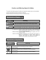
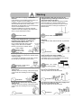
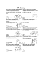
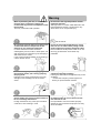
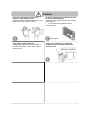
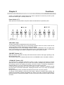
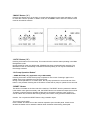
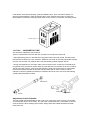
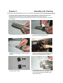
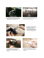
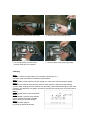
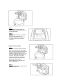
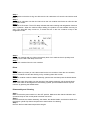
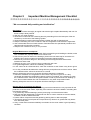
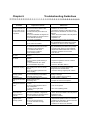
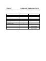
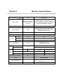
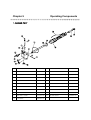
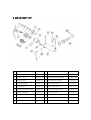
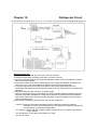
User Manual
Be sure to read this user manual
carefully before using this machine. And
please keep the manual well after
reading it.
SE-A E&C Soft Ice Cream Machine
* This machine is designed for use in Korea.
* This machine cannot be used in any other country
where the electric voltage for its power supply is not available.
* This machine is designed for indoor installation.
Please do not install it outdoors.
* The external appearance, design, color, and/or components
of this machine may be changed without prior notice
for the sake of the Company’s product manufacture.
SSI-300T, TP
CONTENTS
Chapter 1
Safety Precautions.............................................................................. 3
Chapter 2
Installation........................................................................................... 9
Chapter 3
Functions .......................................................................................... 10
Power Switch (“F”)........................................................................... 10
“MIX LOW” Lamp ............................................................................ 10
“MIX REF” Button (“A”).................................................................... 10
“STAND BY” Button (“B”)................................................................. 10
“WASH” Button (“C”)........................................................................ 11
“AUTO” Button (“D”) ........................................................................ 11
“Air Pump Operation Button” ........................................................... 11
“RESET” Button............................................................................... 11
“Air Tube” – CARBURETOR TUBE ................................................. 12
Adjustment of the Pull Handle ......................................................... 12
Chapter 4
Assembly and Cleaning .................................................................... 13
Assembling the Mix Pump SSI-300TP ............................................ 16
Cleaning .......................................................................................... 17
Replenishment of Mix...................................................................... 18
Rinse ............................................................................................... 19
Disassembly and Cleaning.............................................................. 19
Cleaning with a Brush ..................................................................... 20
Chapter 5
Important Machine Management Checklist ...................................... 21
Chapter 6
Troubleshooting Guidelines .............................................................. 22
Chapter 7
Component Replacement Cycle ....................................................... 23
Chapter 8
Machine Specifications ..................................................................... 24
Chapter 9
Operating Components..................................................................... 25
Chapter 10
Refrigerant Circuit............................................................................. 28
Chapter 11
Circuit Diagram ................................................................................. 31
Chapter 1
The Company would like to ensure the safety
of the user or service technician who comes
into contact with the ice cream maker or its
components. For example, safety precaution
labels have been attached to relevant parts of
the machine as advance warnings for the
user or service technician.
“Important Point – Failure to observe any of
the following safety precautions may result in
severe personal injury. Failure to observe any
warning may result in damage to the machine
or its components. If any component is
damaged, it may cause you to incur some
replacement or repair expenses. Please be
careful.”
Safe Operation:
You must not operate the ice cream maker
before reading this user manual. Failure to
follow the instructions in this manual may
result in damage to the equipment, improper
performance, or personal health risk, injury or
death. The Company will not be liable for any
accident attributable to the user’s failure to
follow instructions.
① ever operate the freezer without proper
electrical grounding. Failure to follow this
instruction may result in death due to electric
shock.
Unless the machine is electrically grounded,
there is a danger of electric shock, which
may result in death. Never do any repair
work before turning off the main power
supply of the machine. Failure to follow this
instruction may result in an electric shock.
For more detailed information on using the
ice cream maker safely or any other
information, please contact and consult the
Company’s sales agent from whom you have
Safety Precautions
purchased the machine, the Company’s aftersales service center, or the Company’s
consumer counseling center.
② Do not let any unskilled person operate
this machine. Failure to follow this instruction
is dangerous and may result in a severe
finger or hand injury due to moving parts.
③ Unless all of the service panels and
attached doors are firmly secured by
fasteners (screws), do not operate the freezer.
Failure to follow this instruction is dangerous
and may result in severe injury from moving
parts.
④ Do not block the air inlet or outlet. Air
space of at least over 16cm is required in
front of both sides of the machine, as well as
the back. Also, air space of 11cm is needed
on the floor. Failure to follow this instruction
may result in a drop in the performance of or
damage to the machine.
⑤ Do not put any foreign substance or your
hand into the ice cream outlet. Failure to
follow this instruction is dangerous and may
result in contamination of the machine or an
injury from moving parts.
Do not take apart doors, the dasher and its
blades, the drive shaft, the air pump, or the
mix pump unless all the control switches are
in the OFF position. Failure to follow this
instruction is dangerous and may result in an
injury from moving parts.
⑥ Be careful when taking apart the dasher
assembly. Otherwise there is a danger of
suffering an injury from sharp mixing blades
(LUG POM).
⑦ Size of Noise: Noise must not exceed
78dB(A) when measured at a distance of 1.0
meter from the machine and at a height of
1.6 meters from the floor.
Caution and Warning Signs for Safety
The caution and warning signs for safety are intended to help the user use the machine
properly and therefore prevent accidents or dangers.
Please understand the following and be sure to observe them.
Description of Signs
Sign
Meaning
Warning
Caution
Means that improper use may result in serious injury or death.
Means that improper use may result in personal injury or material
※ “Personal injury” referred to above means any injury or burn that does not
require receiving regular hospital treatment as an outpatient
for an extended period of time.
※ “Material damage” referred to above means damage to property, such as a
house or furniture.
※ “Caution and warning labels” are attached to the main body of the machine. If
labels are contaminated or unclear, please contact the
Company sales agent from whom you purchased the
machine or the Company’s after-sales service center.
Description of Symbols
Symbol
Meaning
Indicates prohibition (i.e. must NEVER do ).
Each specific prohibition is described by a picture or sentence
inside the symbol.
Indicates compulsory actions (i.e. MUST DO without fail).
Each specific compulsory action is described by a picture or sentence
inside the symbol.
Indicates a caution or warning.
Each specific caution or warning is described by a picture or sentence
inside the symbol.
Warning
Have a specialist company install or move the
machine.
If the machine is not installed properly, there is a
danger of accidents such as falling, etc.
Installation work must be performed in accordance
with the relevant laws such as the Korean
Standards, the Road Traffic Act, the Fire Services
Act, the Food Sanitation Act, etc.
Improper installation may result in accidents.
* Please contact the Company sales agent from
whom you purchased the machine.
Observe the laws.
Be sure to plug the machine into a proper
voltage outlet equipped with a grounding
terminal (power voltage: AC200V±10%,
electrical outlet: 50A or over)
GROUNDING
Do not extend the length of the power
TERMINAL
supply cord or allow it to be twisted,
this may cause a fire or electric shock.
power voltage:
AC200V±10%,
220V
220V
POWER
electrical outlet:
ELECTRICAL
SUPPLY
OUTLET
50A or over
Have a specialist company repair the machine.
Imperfect repairs may cause a fire, electric shock,
or personal injury.
* If you think the machine is out of order, contact
the Company’s after-sales service center.
Entrust any repair work to
the service center.
Do not put any heat source near the power
supply cord.
This may cause the covering of the power supply
cord to melt, thus resulting in a fire or electric
shock.
Prohibition
Do not put any heat source near the power
supply cord.
This may cause the covering of the power supply
cord to melt, thus resulting in a fire or electric
shock.
Prohibition
If the electrical outlet you are using is not
equipped with a grounding terminal, be sure to
ground the machine properly.
Unless the machine has been properly grounded,
electricity leaks may cause an electric shock.
Do not connect the ground wire to a gas or water
pipe because there is a danger of explosion or
electric shock.
Ground the machine.
Do not take apart and remodel the
machine.
It may cause a fire, electric shock, or personal
injury.
Prohibition
Always keep the caution and warning labels
clean enough to be easily readable.
If important caution or warning contents are
unreadable, there is a great possibility of improper
use, which may result in accidents.
Check the caution
and warning labels.
Do not put any object on the power supply cord.
Do not let it get twisted or tied.
This may cause a fire or electric shock.
No!
Prohibition
Do not put any object on the power supply cord.
Do not let it get twisted or tied.
This may cause a fire or electric shock.
Prohibition
Warning
Do not put any combustible gas or flammable
substance (such as benzene, gasoline,
thinner, and LP gas) inside or near the
machine.
This may cause an explosion, fire, or personal
injury.
Put into the machine only the products
specified in the usage instructions or on the
name plate.
Putting in any unspecified product may cause
the machine to break down.
Put in only the
specified product.
Prohibition
Do not use any combustible gas or
flammable substance (such as benzene,
gasoline, thinner, and LP gas) near the
machine.
This may cause an explosion, fire,
or personal injury.
Do not touch the operation section.
Do not touch the operating components inside
the machine.
It can result in injury.
No touch!
Prohibition
When removing the wiring housing, be sure
to grasp its main body to pull it out.
Forcibly removing the housing by pulling the cord
may cause an electric shock or a breakdown.
If there is a strange sound, smell, or smoke
coming out of the machine, remove the
power supply plug from the outlet.
Continuing to use it in such a case may cause a
fire or electric shock.
CLATTERING
HOUSING
Do not touch any electrical component or the
power plug with a wet hand.
This may cause an electric shock.
Prohibition
Do not put any object on the machine.
This may cause the machine to overturn or the
object to fall.
Prohibition
ROLLING
Pull out the plug.
Do not sit on the machine. Do not shake or
tilt it.
This may cause the machine to
overturn or to break down.
Prohibition
Beware of the metal corners and the
ventilation grooves of the machine.
Do not touch the metal corners and the
ventilation grooves.
Warning
When replenishing the mix, be careful to
prevent rain or snow from coming into
contact with any electrical component inside
the machine.
This may cause abnormal operation.
Do not touch the high-temperature section
inside the machine.
Although there is a caution label attached to the
high-temperature section, contact with it may
cause burns or an unexpected injury.
Do not touch!
Be careful to prevent water from coming into
contact with internal components of the
machine or any electrical component.
In cases where the machine has been
submerged by a flood, water or other liquid, call
and request for an inspection by the Company’s
after-sales service center.
It may cause electrical leakage, thus resulting in
a fire or electric shock.
In case of not using the machine for a long
time, be sure to clean it after pulling out the
power supply plug from the electrical outlet.
If the machine is not kept clean while not in use,
mix may go bad and/or colon bacilli may
proliferate.
When removing the power supply plug from
the electrical outlet, pull it out by grasping
the plug head.
Pulling the plug out by grasping the cord may
damage it, thus resulting in a fire or electric
shock.
When disposing of the machine, entrust it to
a disposal specialist company.
Leaving it to stand idle and neglected may cause
accidents.
※ Contact the Company’s sales agent from
whom you purchased the machine.
Clean the area between both terminals of the
power supply plug and its contact surface to
be free of foreign substances.
Foreign substances may cause poor electrical
conduction, thus resulting in a fire.
In case of selling or transferring the machine
to someone else, be sure to hand over the
user manual as well.
It is impossible to use the machine properly
without the user manual and improper use may
cause accidents.
User
Manual
Caution
In case of cleaning the inside of the
machine, wear rubber gloves.
Cleaning without wearing rubber gloves may
result in an electric shock or injury.
In case of cleaning the condenser, be sure
to wear protective gloves.
There is a danger of a hand injury from sharp
metal edges.
(※ In the case of the condenser with a
cooling device)
Wear gloves.
Remove the stagnating water from the
water trap at regular intervals.
If stagnating water decays the machine or
overflows its bottom, it may cause a fire or
electric shock.
In case of replacing or repairing the power
supply cord, entrust it to a specialist
company or the Company’s after-sales
service center.
SERVICE CENTER
Chapter 2
Installation
Cooling System
The cooling system requires free space of at least over 20 centimeters in front of each side of
the machine for the sake of proper air-flow.
A lack of proper free space may decrease the cooling performance of the freezer and/or cause
permanent damage to the compressor.
Electrical Connection
Each freezer requires the supply of electrical power.
Please check the fuse, current, and electrical specifications. Refer to the connection diagram at
the back of the machine.
Caution : This system requires proper grounding. Otherwise, there is a danger of severe
personal injury due to electric shock. The rotation of the dasher must be clockwise.
Caution : The following must be performed by a trained A/S technician:
Change the lead wire in the dasher motor to ensure the correct rotation of the singlephase power supply.
(Follow the connection diagram printed on the motor.)
The electrical connection is designed to be directly linked with the main control box
inside the panel next to the upper left part of the machine.
Chapter 3
Functions
Caution: An audible alarm sounds whenever a button is pressed. To cancel any function, press
the function button again. The lamp will turn off.
Power Switch (“F”)
When placed in the ON position, the power switch activates the front operation panel.
“MIX LOW” Lamp
The MIX LOW lamp is located above the function buttons.
If it is blinking, the supply level of mix in the storage container is too low. In such a case, the mix
storage container must be replenished as soon as possible.
The quantity level of mix in the storage container must be maintained at 8cm or higher at all
times. If the amount of mix is below this minimum level, it may freeze up, which consequently
may result in damage to the dasher, its blades, the drive shaft, and/or the outlet.
“MIX REF” Button (“A”)
When this button is pressed, the lamp will indicate that the machine has begun operating in the
Mix Refrigeration mode.
This function cannot be canceled unless the AUTO or STANDBY mode is canceled in advance.
“STAND BY” Button (“B”)
The machine has a separate refrigeration system in order to prevent the spread of bacteria
while the mix is in the hopper at 4.4°C or less. This function is designed to prevent the mix in
the freezing cylinder from getting excessively cold and to keep it consistently refrigerated in
storage at about 1.7°C to 4.4°C when the machine is not in use for a long time.
In this case, after pressing this key, remove the upper air orifice, reverse the carburetor so that
the end without a hole faces downward. Pressing this button turns on the lamp and activates
this function.
During the Standby mode, the WASH and AUTO functions are in the OFF position.
To resume normal operation, press the AUTO button. When the machine stops rotating, the
products in the freezing cylinder are probably very sticky. In this case, reverse the carburetor so
that the end with a hole faces downward in order to let air flow inside and then install the upper
air orifice.
“WASH” Button (“C”)
Pressing this button turns on the lamp. It means that the dasher motor starts operating. In order
to make the machine operate in WASH mode, the STANDBY button and/or the AUTO button
must be canceled in advance.
“AUTO” Button (“D”)
Pressing this button turns on the lamp. This means that the machine starts operating in the Main
Refrigeration mode.
During the AUTO mode, the WASH and STANDBY functions are automatically canceled. The
MIX REF function is automatically controlled so that the quantity of mix may be maintained in
the storage container.
“Air Pump Operation Button”
– PUMP BUTTON (“E”) (applicable only to SSI-303SP)
Pressing this button causes the air pump to operate for one minute. Pressing it again in the
middle of the pump operation turns off the air pump.
During normal operation for ice cream sales, the air pump operates for 10 seconds even if the
button is not pressed. Pressing the AUTO button causes the air pump to operate for 30 seconds.
“RESET” Button
This button is located on the front side of the machine. The RESET function protects the dasher.
If the dasher motor gets excessively cold, the RESET device is activated and stops the machine.
To restart a machine that has stopped working due to excessive coldness, press “AUTO” to
cancel rotation first, and then after turning off the power switch, firmly press the RESET button.
Caution : Do not press the RESET button using a metallic object.
Turn on the power switch.
Press “WASH” and observe how the machine responds. Open the side panel. Check to see
whether the dasher motor rotates the dasher shaft clockwise without being interrupted.
If the dasher motor rotates properly, press the WASH button, which cancels its rotation. To
resume normal operation, press the AUTO button. If the machine stops again or shows any
abnormalities, contact the Company’s after-sales service center or consumer counseling center.
Reset Button
“Air Tube” – CARBURETOR TUBE
The air tube is supplied for two purposes.
There is a hole at the one end of the tube, but there is no hole at the other end.
* After replenishing the mix, lubricate the O-ring placed at the end with a hole, and then insert
the tube into the hole on the mix container. Whenever ice cream is sold, the pull handle is raised
and new mix from the mix container flows into the freezing cylinder together with air.
* During the suspension of ice cream sales, remove the air orifice. At this time, lubricate the Oring placed at the end without a hole and then insert the tube into the hole on the mix container.
This is to prevent mix from moving into the freezing cylinder. When resuming ice cream sales,
reverse the insertion direction of the tube and then insert the air orifice, which is used to
maintain continuous operation and allows a sufficient amount of mix to move into the freezing
cylinder after the handle is pulled.
AIR ORIFICE
SALE
INCREASE
O-RING
DECREASE
Adjustment of the Pull Handle
The pull handle must be adjusted so that a cup of ice cream may come out every 10 seconds.
To increase the amount of ice cream, turn the screw counterclockwise. To decrease it, turn the
screw clockwise. When washing the machine, always press the handle downward and then
remove the mix.
Chapter 4
Assembly and Cleaning
In principle, start the machine when it is fully dry. After operation, it needs to be taken apart,
washed and kept dry after that. These operation procedure instructions provide an
understanding of how to assemble the freezer and clean its components. Be sure to use fresh
mix materials.
① Apply edible grease (lube) to the shaft.
② Fit Javara packing (flexible packing) in the
groove at the end and apply lube.
③ Apply lube inside the flexible packing and
the shaft. Do not apply it to the flat part of
its end.
④ Insert the shaft into the internal bearing
portion. The shaft should be inserted firmly
into the end to prevent it from shaking.
(○)
(×)
⑤ When fitting the flexible packing, keep its
projecting part outside.
⑥ Fit the plastic blades into the dasher. Once
dasher blades have worn, the performance
of the machine decreases. Replace them
after three months.
⑦ The dasher blades should be inserted
towards inside the cylinder to be fitted with
the shaft. They must be inserted correctly
and the dasher must not come out.
⑧ Try to turn the dasher blades by hand. If
they don’t turn, they are in the right position
to fit the internal grooves well.
⑨ Fit the gasket and the white
bearing into the dasher cover.
When fitting the bearing,
insert it by keeping its wider
part facing towards the dasher
cover. Do not apply grease.
⑩ Fit the dasher cover into the machine
and then insert four hand screws.
Tighten them in a diagonal order but not
too hard.
⑪ Apply lube to the packing to be fitted
inside the shaft. Replace it if it has been
damaged.
⑫ Apply edible grease into the hole of the
dasher cover also, and insert the shaft
downward.
⑬ Fit the auxiliary handle into the handle
and tighten the screw firmly.
⑭ Mount the draining water trap and its
cover in position.
⑮ Fit the hand into the shaft and join the shaft
to the machine by inserting it sideways.
(16) Mount the side and back drain
openings in position.
Assembling the Mix Pump SSI-300TP
and Disassembling It in Reverse Order
① Apply edible grease slightly inside the
piston.
② Apply edible grease slightly onto the
ring also.
③ Insert the piston into the valve body.
④ Apply edible grease inside the cylinder
also.
⑤ Insert the valve body into the cylinder
correctly to fit the cylinder grooves well.
(Pay attention to the groove direction.)
⑥ Apply edible grease also to the mix
inlet, the ring, and the rubber at the end.
⑦ Insert the mix inlet into the valve body.
⑧ Secure it firmly by inserting the pin.
⑨ Fit the valve body onto the rotary
grooves inside the mix container.
⑩ Secure it firmly using a securing clamp.
Cleaning
Step 1
Prepare 7.6 liters of wash solution. (For example, a detergent, etc.)
Use warm water and follow manufacture’s specifications.
Step 2
Pour 7.6 liters of wash solution into both hoppers to make it flow into the freezing cylinder.
Step 3
Clean the mix container using a brush while the wash solution is flowing into the freezing
cylinder. When cleaning the mix container, be particularly careful about brushing the hole of the
container, the carburetor, the gasket, and the mix quantity level sensing rod on the front wall of
the container.
Step 4
Put the power switch in the ON position.
Step 5
Press “WASH”. Then the wash solution
will be stirred in the freezing cylinder.
Keep it stirring for about 5 minutes.
Step 6
Empty the wash solution
by pulling the handle downward.
Step 7
Lift the handle upward, press the
WASH button and the dasher motor
will stop operating.
Step 8
Fix the gasket of the mix container to
the rim of the top part of the
container. Insert the air carburetor
into the hole of the raw material
container.
Replenishment of Mix
Step 1
Place the container under the dasher
assembly and then open the handle.
Pour 7.6 liters of fresh mix into the mix
container to allow it to flow into the
freezing cylinder. At this time, you can
force the remaining wash solution to
come out. When mix is fully and
powerfully flowing into the dasher
outlet, discharge wash solution by
pressing the draw handle.
Caution: Be sure to use fresh mix
when replenishing it.
Step 2
When mix begins to flow stably, lift the
draw handle upward.
Step 3
Apply grease so that the O-ring can slide over the air carburetor to fit onto the end with a small
hole.
Step 4
Insert the air carburetor into the mix inlet hole on the mix container and fit the air orifice into the
end without a hole.
Step 5
Press the AUTO button. The AUTO lamp indicates that main freezing and refrigeration functions
are in operation. When the machine stops rotating, the product now has suitable viscosity for
sale. If the MIX REF lamp comes on, it means that mix in the mix container is kept in the
refrigeration mode.
Step 6
Fill the mix container with mix. When the quantity level of mix reaches the mix quantity level
sensing rod, the MIX LOW lamp will turn off.
Step 7
Put the mix container lid on the mix container.
Rinse
Step 1
Pour 2 gallons (7.6 liters) of cold, clean water into the mix container. Clean the mix container,
the mix container hole and the sensing rod by scrubbing them with a brush.
Step 2
Place the container under the dasher assembly, pull the lever and then press the WASH button.
Step 3
When rinse water flows stably into the opening of the dasher assembly, pull the handle down.
When rinse water is discharged from the freezing cylinder, pull the handle and then stop the
machine by pressing the WASH button.
Disassembly and Cleaning
Step 1
Make sure that the power switch is in the OFF position. Make sure also that the indication and
operation lamps on the control panel have been turned off.
Step 2
Remove the bolts, the dasher assembly, the dasher, the dasher blades, and the drive shaft from
the freezer cylinder. Dip these components in wash solution for cleaning.
Step 3
Remove the front-side water trap and the dreg lid.
Cleaning with a Brush
Step 1
Use warm water or wash solution.
Step 2
Remove the flexible packing from the drive shaft.
Step 3
Remove the following components from the dasher assembly.
• Gasket
• Front bearing
• Handle
• Design cap
• Piston
Remove O-rings.
Caution: When removing an O-ring, take it out by grasping it with a new towel. Apply upward
force until the O-ring bounces out of the groove. Push its upper part down with the other hand.
The O-ring will then come out of the groove for easy removal. When removing more than one Oring, always remove the rear one first. By doing so, you can make each rear O-ring to come out
by sliding over the O-rings ahead of them without falling into otherwise empty grooves.
Step 4
Remove O-rings from the air carburetor and the air orifice.
Step 5
Inject a very small amount of wash solution into the freezing cylinder. Clean the rear bearing of
the freezing cylinder by scrubbing it with a cleaning brush.
Step 6
Remove the water trap and clean it.
Caution: If there is too much mix in the water trap, empty it first before cleaning.
Step 7
Clean all the disassembled components thoroughly with wash solution and make sure that
grease and mix have been completely removed. Pay special attention when cleaning the dasher
assembly. Lay all the cleaned components on a clean place and wipe them with dry cloth or wait
until they are fully dry.
Step 8
Clean all external surfaces of the machine thoroughly.
Chapter 5
Important Machine Management Checklist
“We recommend daily washing and sterilization.”
Sterilization
1. Clean the machine thoroughly at regular intervals through complete disassembly and use of a
brush to keep it always sterile.
2. Use only very clean brushes.
3. Clean the mix inlet hole with a cleaning brush by extending it from the lower part of the mix
container up to the rear of the freezing cylinder.
4. Clean the bearing portion behind the freezing cylinder also with a cleaning brush.
5. Keep the remaining mix in the container in the mix refrigeration mode and use it again later.
6. Use a reasonable amount of wash solution. Read and follow the operational procedure and
cleaning method instructions carefully.
7. Keep the mix container at 40°F (4.4°C) or below.
Regular Maintenance Checkpoints
1. Replace any scratched or damaged blade. Before assembling and installing the dasher, make
sure the blades are properly attached in a helical curve.
2. Check for any trace of wear on the bearings. (Check the rear water trap for excessive mix
leakage.) Also check to make sure the bearing has been cleaned properly.
3. Remove any oil and mix dreg from the bearing and the hexagonal drive socket with a
screwdriver and a towel
4. Replace any worn, torn or loose O-rings or seals with new ones.
5. For grease application, follow the “assembly” procedure.
6. In the case of an air-cooled machine, check the condenser to see if there is any dust or grime
on it. A dirty condenser decreases the cooling efficiency and performance of the machine. Clean
the condenser with a soft brush at least once a month.
Warning: Always be sure to turn the power off before cleaning the condenser.
7. Check the condenser for refrigeration to see if there is any dust or grime on it. A dirty
condenser decreases the refrigeration capacity of the mix container. It is necessary to clean
the condenser with a soft brush at regular intervals in order to prevent dust from building up
on it. Do not clean between fins with a screwdriver or any other sharp-ended metal.
Warning: Always be sure to turn the power off before cleaning the condenser.
Storage during a Long Non-Use Period
In case of non-use for a long time, the following preventive measures are very important for the
protection of the ice cream maker, especially if the machine has been installed in a building that
has freezing problems.
1. To prevent any electrical damage, pull the power plug out of the electrical outlet.
2. Remove and pack detachable components from the ice cream machine such as the dasher,
its blades, the drive shaft and the like.
3. Protect rubber components and the gasket by packing them in desiccant paper.
4. Thoroughly remove from all parts and components any dried mix or grease that may attract
mice and other pests.
5. Carry out the above-mentioned faithfully to maintain the ice cream maker in good operating
condition.
Chapter 6
Problem
1. The machine is in
the AUTO mode, but
no ice cream comes
out when the handle
is pressed.
2. Product too hard.
3. Product too thin.
4. The mix container
too cold.
5. The mix container
too warm.
6. The drive shaft held
in the drive coupling.
7. The wall of the
freezing cylinder
damaged.
8. Too much mix
leaking into the water
trap.
9. Too much mix
leaking from the door
outlet
10. The machine
stops when the
“AUTO” button is
pressed.
11. No product
supplied to the
freezing cylinder.
Troubleshooting Guidelines
Expected Causes
Measures
a. The dasher inlet hole is clogged.
b. Cannot reset the dasher motor.
c. The dasher rotates
counterclockwise (when seen from
operator).
d. The circuit breaker has tripped into
the OFF position or the fuse is blown.
e. Mix blended incorrectly.
f. Air orifice not installed.
a. Viscosity adjustment needed.
a. Adjust the temperature in the mix container.
b. Reset the ice cream maker.
c. Contact the Company’s after-sales service
center and have the dasher corrected to rotate
clockwise.
d. Switch the circuit breaker to the ON position
or replace the fuse.
e. Replenish mix.
f. Install the air orifice in the air carburetor.
a. Maintain proper sweetness in case of
using dedicated liquid material and powder.
b. Install the air orifice in the air carburetor.
a. Maintain proper sweetness in case of
using dedicated liquid material and powder.
b. Provide proper air-flow for the condenser.
c. Replace the dasher blade with a new one.
d. Clean the condenser once a month.
e. Use new mix.
a. Adjust the temperature in the mix hopper.
b. Air orifice not installed.
a. Viscosity adjustment needed.
b. Insufficient clearance around the
machine (for air-cooled type)
c. The dasher blade worn.
d. Dust on the condenser.
e. Mix validity expired.
a. Temperature adjustment function
broken.
a. Temperature adjustment function
broken.
b. The container gasket missing or
defective.
c. The container lid not in place.
d. The “MIX REF” lamp is off.
a. The corners of the drive shaft or
the coupling worn out in a circular
shape.
b. Mix and grease gathered at the
drive coupling.
a. The dasher assembly bent.
b. The front bearing on the dasher
assembly missing or worn.
a. The flexible packing for the drive
shaft missing or worn.
b. Bearing worn.
a. The O-ring on the piston missing
or worn.
b. Wrong grease applied to the Oring of the piston.
c. Wrong grease (petroleum
lubricant).
a. No power supplied.
b. The circuit breaker is tripped into
the OFF position or the fuse is blown.
c. Can’t reset the mixer motor.
a. Improper quantity of mix in the mix
container.
b. The mix inlet hole frozen.
c. The air carburetor wrongly
installed.
a. Adjust the temperature in the mix container.
b. Replace the gasket for the mix container.
c. Put the lid in place.
d. Press the “MIX REF” button.\
a. Find the cause(s) and replace components
if necessary. Do not apply grease to the
hexagonal end of the drive shaft.
b. Clean the bearings regularly with a brush.
a. Replace the dasher and correct the
cause(s) of damage.
b. Install or replace the front bearing.
a. Install properly or replace it.
b. Request for service and replace it.
a. Install properly or replace it.
b. Use correct grease.
c. Use correct (edible) grease.
a. Check the power supply system.
b. Switch the circuit breaker to the ON position
or replace the fuse.
c. Reset the machine.
a. Fill the mix container with mix.
b. Adjust the temperature in the mix container.
c. Install the air carburetor in the mix inlet hole
using the end with a small hole.
d. Install the air orifice in air carburetor.
Chapter 7
Component
Component Replacement Cycle
Every three months
Flexible packing for the drive shaft
O
Scrapper blade
O
Dasher assembly gasket
O
Dasher assembly bearing
O
Piston O-ring
O
O-ring
O
Air carburetor O-ring
O
Air orifice O-ring
O
White coarse brush
Black coarse brush
Every six months
Inspection and replacement
(when necessary)
Inspection and replacement
(when necessary)
Chapter 8
Machine Specifications
Item
Spec
Unit
Specifications
Selling capacity
May vary depending on
the ice cream maker
and mixes.
Indefinite sales (one 100cc serving per 30
seconds). Based on an ambient temperature
of 30°C or below, humidity of 60% or below
and mix temperature 5°C or below.
Production capacity
kg/hr
10
Cooling capacity
ditto
Can begin selling 12 minutes after cylinder
tank operation. Mix reaches -6.5°C at the
ambient temperature of 30°C.
Cylinder capacity
liter
3.2
Mixing tank capacity
liter
18
Height
mm
790
Width
mm
460
Depth
mm
770
Dimensions
Power supply
Weight
Before Packaging
Single phase 220 / 60
Single phase 230 / 50
330
kg
After Packaging
Compressor
Cooling
system
V / Hz
Freezer
Refrigerator
350
Tecumseh
CAJ2446Z
SAMSUNG
SD137H-L1Z
Output
HP
1.2
1/10
Fan motor Output
W
100
10
Max. Power consumption
KW
3.1
Control
MICOM-CONTROL
Free service parts supplied
with the machine
6 dasher blades, 4 piston rings, 2 brushes, 2
outlet rings, 2 flexible hose rings and 1 can of
edible grease (Highness)
Option
Mix pump (separate model)
Chapter 9
Operating Components
1. DASHER PART
NO
COMPONENT NAME
CODE
NO
COMPONENT NAME
CODE
1
DASHER COVER
6100124-00
11
DASHER LEVER SHAFT
3140060-00
2
PISTON L R
3030084-00
12
O-RING LEVER SHAFT
3030085-00
3
SHAFT PIN
3150029-00
13
MIXING SHAFT
3140058-00
4
SHAFT POM PACKING
2320027-00
14
DASHER BEARING
3100010-00
5
JOINT BOLT
2140121-00
15
DASHER ASS'Y
4030029-00
6
PACKING DASHER COVER
3030075-00
16
DASHER LUG POM
4030027-00
7
LEVER DASHER
3090018-00
17
SHAFT TOP PULLY
3140059-00
8
SCREW ADJUST
3010373-00
18
PACKING JABARA
3030076-00
9
JOINT BOLT DOWN
2140123-00
19
AIR VENT SHAFT
3140085-00
10
STAR MADE
3880004-00
2. CASE PART
NO
COMPONENT NAME
CODE
NO
COMPONENT NAME
CODE
1
ASS’Y CABINET
4120179-00
9
BASE CANISTER SHEET
3180064-01
2
GASKET FOOD PAN
6560004-00
10
DRAIN BOX UP
3170601-00
3
COVER FOOD PAN
3080021-00
4
RING CABURATOR
2320025-00
5
AIR CABURATOR
3390037-01
6
RING ORIFICE
2320026-00
7
ORIFICE
3400062-01
8
DRAIN BOX BOLT
3360066-00
2. MIXING PUMP PART
NO
COMPONENT NAME
CODE
NO
COMPONENT NAME
CODE
1
AIR PUMP VALVE BODY
3400070-01
11
AIR PUMP PISTON
3030089-00
2
AIR INLET SEAL
3030092-00
12
AIR PUMP LOCKING SHAFT
3140075-00
3
AIR INLET RING
3030095-00
13
AIR PUMP PISTON BODY
3030138-00
4
AIR PUMP SPRING
3230031-00
14
AIR PUMP BRACKET
3010402-00
5
RUBER FOFAT
3030091-00
15
DRIVE SHAFT RING
3030101-00
6
AIR PUMP PISTON HOLDER
3030090-00
16
AIR PUMP ROTARY SHAFT
3140084-00
7
MAIN PISTON RING
3030102-00
17
PUMP OUT PIPE
3250353-00
8
PISTON END RING
3030098-00
18
DRIVE SHAFT SMALL RING
3030096-00
9
CHECK BAND TWO
3030099-00
19
AIR PUMP LOCKING SPRING
3030093-00
10
CHECK BAND ONE
3030100-00
20
PUMP PIPE FEED RING
3030097-00
Chapter 10
Refrigerant Circuit
Refrigerant Injection
1. Remove the left-side and rear-side covers from the machine.
2. Identify the improperly operating compressor and remove its cap.
3. Close the manifold gauge by turning its left and right handles. Close the refrigerant container
valve by turning its handle.
4. Connect the central hose of the manifold gauge to the refrigerant container and tighten the
connection. (Turn over the refrigerant container and fill it with liquid refrigerant.)
5. Connect the joint at the end of the low-pressure hose to the low-pressure part of the
compressor and tighten the connection. Be careful not to over torque the screw threads while
tightening.
6. Start the cooling unit after turning on its power supply.
7. Open the low-pressure gauge completely by turning its handle. Watch the reading of the lowpressure gauge after operating the cooling unit for at least 30 minutes and inject refrigerant
while opening and closing the valve handle repeatedly so that the reading may be the same
as the prescribed value.
8. After finishing refrigerant injection, fit the cap onto the compressor.
* Caution: The above-mentioned refrigerant injection method is based on an ambient
temperature of 32°C and humidity of 60%. The reading of the pressure gauge may
vary depending on the ambient temperature.
* For freezing: 1300g under the nonload condition, low pressure of 19~18PSI, high pressure
of 250~255PSI
* For refrigeration: R-404 220g, low pressure of 0~7PSI
* E.P.R.: 68~70PSI
Chapter 11
Circuit Diagram
CIRCUIT DIAGRAM
TERMINAL
BLOCK
L
1
W
1
W
2
W
W
SWITCH
L1
L1
3
N
T1
ELB or
NSF
CONTROL
PCB
HPS
MC2
MC1
T1
②
RESET
S/W
2
BR
OL
5
EOCR
GY
6
BR
BEATER
③
O
R
GY
Tb
Y
8
COMP1
FAN1
BR
MOTOR
EOCR
4
BL
Tc
1
* WIRE COLOR
B
BLACK
BR BROWN
R
RED
O
ORANGE
Y
YELLOW
BL BLUE
V
VIOLET
GY GRAY
WHITE
W
GREEN
G
* CONTRACTION
COMP1
COMP2
MOTOR
GEARD MOTOR
FAN1
FAN2
MC1
MC2
EOCR
HPS
* MODEL
SSI-300TP
SSI-300T
CIC-322T
Domestic
Export
Old Model
New Model
BR
R
T2
T2
MC1
A1
COMP2
MC2
L2
L2
B
O
B
A1
FAN2
A2
B
Freezer compressor
Refrigerator compressor
Freezer motor
Overrun pump motor
Freezer fan motor
Refrigerator fan motor
Magnetic contactor for freezer compressor
Magnetic contactor for freezer motor
Over current relay for freezer motor
High pressure switch for freezer compressor
MC1
B
B
A2
B
L1
EOCR
L2
B
①
MAIN
PCB
CN2
1
CN5
2
MIX
SENSOR
DRAW
S/W
2
Include ①
Exclude ①
Exclude ①
Include ②
Exclude ②
Include ③
Exclude ③
MC2
A2
A2
B
A1
A1
GEARD
MOTOR
CN3
3
CN4
1
1
3
2
CYLINDER
SENSOR
SENSOR
CODE : 3800479-03
MEMO
If you need after-sales services...
If anything wrong is
discovered during use:
First of all, pull out the
power plug.
Your request will be
addressed promptly.
Repairs are finished!
Contact any office
∽ Warranty ∽
Product Name:
Model:
Date of Purchase:
Customer Name:
Tel.
Address:
Sales Agent:
Tel.
Address:
Warranty
period:
one (1)
year
Headquarters : 78B 3LOT, 648-2,Namdonggongdan 2, Gojan-dong,
Namdong-gu, Incheon, Korea
TEL
FAX : 82-32-814-1798
Machine: 82-32-814-0693
Specifications