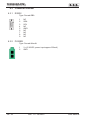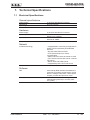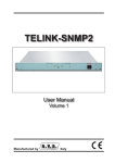
1
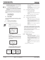
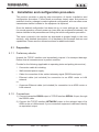
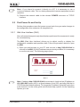
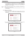
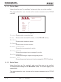
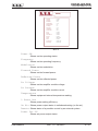
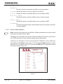
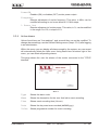
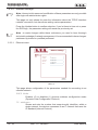
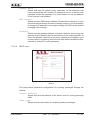
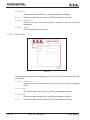
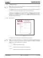
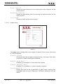
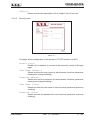
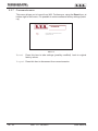
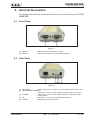
TCP/IP-INT-PTX User Manual Volume 1 Manufactured by Italy File Name: 03_TCP_IP-INT-PTX_ING_1.0.indd Version: 1.0 Date: 28/09/2007 Revision History Date Version 28/09/2007 1.0 Reason First Edition Editor J. H. Berti TCP_IP-INT-PTX - User Manual Version 1.0 © Copyright 2007 R.V.R. Elettronica SpA Via del Fonditore 2/2c - 40138 - Bologna (Italia) Telephone: +39 051 6010506 Fax: +39 051 6011104 Email: [email protected] Web: www.rvr.it All rights reserved Printed and bound in Italy. No part of this manual may be reproduced, memorized or transmitted in any form or by any means, electronic or mechanic, including photocopying, recording or by any information storage and retrieval system, without written permission of the copyright owner. TCP/IP-INT-PTX Table of Contents 1. 2. 3. 3.1 3.2 4. 4.1 5. 5.1 5.2 5.3 6. 6.1 6.2 6.3 7. 7.1 Preliminary Instructions Warranty First Aid Electric shock treatment Treatment of electric burns Unpacking General Description Installation and configuration procedure Preparation First Power-On and Set-Up Management Software External Description Front Panel Rear Panel Connector Pinouts Technical Specifications Electrical Specifications User Manual Rev. 1.0 - 28/09/07 1 1 2 2 2 3 3 4 4 5 6 19 19 19 20 21 21 TCP/IP-INT-PTX This page was intentionally left blank ii Rev. 1.0 - 28/09/07 User Manual TCP/IP-INT-PTX IMPORTANT The lightning flash with arrowhead, within a triangle, is intended to alert the user of the presence of dangerous voltage that may constitute a risk of electric shock. The exclamation point within an equilateral triangle is intended to alert the user to the presence of important operating and maintenance (servicing) instructions in the literature accompanying the equipment. 1. Preliminary Instructions WARNING: This equipment is fitted with earth connections both in the power cord and for the chassis. Make sure both are properly connected. • General Warnings Operation of this equipment in a residential area may cause radio interference, in which case the user may be required to take adequate measures. This equipment should only be operated, installed and maintained by “trained” or “qualified” personnel who are familiar with risks involved in working on electric and electronic circuits. “Trained” means personnel who have technical knowledge of equipment operation and who are responsible for their own safety and that of other unqualified personnel placed under their supervision when working on the equipment. “Qualified” means personnel who are trained in and experienced with equipment operation and who are responsible for their own safety and that of other unqualified personnel placed under their supervision when working on the equipment. The specifications and data contained herein are provided for information only and are subject to changes without prior notice. R.V.R. Elettronica SpA disclaims all warranties, express or implied.While R.V.R. Elettronica SpA attempts to provide accurate information, it cannot accept responsibility or liability for any errors or inaccuracies in this manual, including the products and the software described herein. R.V.R. Elettronica SpA reserves the right to make changes to equipment design and/or specifications and to this manual at any time without prior notice. WARNING: Residual voltage may be present inside the equipment even when the ON/OFF switch is set to Off. Before servicing the equipment, disconnect the power cord or switch off the main power panel and make sure the safety earth connection is connected. Some service situations may require inspecting the equipment with live circuits. Only trained and qualified personnel may work on the equipment live and shall be assisted by a trained person who shall keep ready to disconnect power supply at need. R.V.R. Elettronica SpA shall not be liable for injury to persons or damage to property resulting from improper use or operation by trained/untrained and qualified/unqualified persons. WARNING: The equipment is not water resistant. Any water entering the enclosure might impair proper operation. To prevent the risk of electrical shock or fire, do not expose this equipment to rain, dripping or moisture. Please observe local codes and fire prevention rules when installing and operating this equipment. WARNING: This equipment contains exposed live parts involving an electrical shock hazard. Always disconnect power supply before removing any covers or other parts of the equipment. Ventilation slits and holes are provided to ensure reliable operation and prevent overheating; do not obstruct or cover these slits. Do not obstruct the ventilation slits under any circumstances. The product must not be incorporated in a rack unless adequate ventilation is provided or the manufacturer’s instructions are followed closely. WA R N I N G : T h i s e q u i p m e n t c a n r a d i a t e radiofrequency energy and, if not installed in compliance with manual instructions and applicable regulations, may cause interference with radio communications. User Manual • Notice concerning product intended purpose and use limitations. This product is a radio transmitter suitable for frequencymodulation audio radio broadcasting. Its operating frequencies are not harmonised in designated user countries. Before operating this equipment, user must obtain a licence to use radio spectrum from the competent authority in the designated user country. Operating frequency, transmitter power and other characteristics of the transmission system are subject to restrictions as specified in the licence. 2. Warranty La R.V.R. Elettronica S.P.A. warrants this product to be free from defects in workmanship and its proper operation subject to the limitations set forth in the supplied Terms and Conditions. Please read the Terms and Conditions carefully, as purchase of the product or acceptance of the order acknowledgement imply acceptance of the Terms and Conditions. For the latest updated terms and conditions, please visit our web site at WWW.RVR.IT. The web site may be modified, removed or updated for any reason whatsoever without prior notice. The warranty will become null and void in the event the product enclosure is opened, the product is physically damaged, is repaired by unauthorised persons or is used for purposes other than its intended use, as well as in the event of improper use, unauthorised changes or neglect. In the event a defect is found, follow this procedure: 1 Contact the seller or distributor who sold the equipment; provide a description of the problem or malfunction for the event a quick fix is available. Sellers and Distributors can provide the necessary information to troubleshoot the most frequently encountered problems. Normally, Sellers and Distributors can offer a faster repair service than the Manufacturer would. Please note that Sellers can pinpoint problems due to wrong installation. 2 If your Seller cannot help you, contact R.V.R. Elettronica and describe the problem; if our staff deems it appropriate, you will receive an authorisation to return the equipment along with suitable instructions; 3 When you have received the authorisation, you may return the unit. Pack the unit carefully before shipment; use the original packaging whenever possible and seal the package perfectly. The customer bears all risks of loss (i.e., R.V.R. shall not be liable for loss or damage) until the package reaches the R.V.R. factory. For this Rev. 1.0 - 28/09/07 / 22 TCP/IP-INT-PTX reason, we recommend insuring the goods for their full value. Returns must be sent on a C.I.F. basis (PREPAID) to the address stated on the authorisation as specified by the R.V.R. Service Manager. Units returned without a return authorisation may be rejected and sent back to the sender. 4 Be sure to include a detailed report mentioning all problems you have found and copy of your original invoice (to show when the warranty period began) with the shipment. 3.1.2 Please send spare and warranty replacement parts orders to the address provided below. Make sure to specify equipment model and serial number, as well as part description and quantity. R.V.R. Elettronica SpA Via del Fonditore, 2/2c 40138 BOLOGNA ITALY Tel. +39 051 6010506 3. First Aid All personnel engaged in equipment installation, operation and maintenance must be familiar with first aid procedures and routines. 3.1 Electric shock treatment 3.1.1 If the victim is unconscious Lay the victim down on his/her back on a firm surface. • the neck and tilt the head backwards to free One rescuer: give 2 quick rescue breaths after each 15 compressions. • Two rescuers: one rescue breath after each 5 compressions. • Do not stop chest compressions while giving artificial breathing. • Call for medical help as soon as possible. If the victim is conscious • Cover victim with a blanket. • Try to reassure the victim. • Loosen the victim’s clothing and have him/her lie down. • Call for medical help as soon as possible. 3.2 Treatment of electric burns 3.2.1 Large burns and broken skin Follow the first aid procedures outlined below. • • • Cover affected area with a clean cloth or linen. • Do not break any blisters that have formed; remove any clothing or fabric that is stuck to the skin; apply adequate ointment. • Administer adequate treatment for the type of accident. • Get the victim to a hospital as quickly as possible. • Elevate arms and legs if injured. If medical help is not available within an hour, the victim is conscious and is not retching, administer a solution of table salt and baking soda (one teaspoon of table salt to half teaspoon of baking soda every 250 ml of water). the airway system (Figure 1). Have the victim slowly drink half a glass of solution for four times during a period of 15 minutes. Stop at the first sign of retching. Do not administer alcoholic beverages. Figure 1 • If needed, open the victim’s mouth and check for breathing. • If there is no breathing, start artificial respiration without delay (Figure 2) as follows: tilt the head backwards, pinch the nostrils, seal your mouth around the victim’s mouth and give four fast rescue breaths. 3.2.2 Minor burns • • Apply cold (not ice cold) strips of gauze or dress wound with clean cloth. • Do not break any blisters that have formed; remove any clothing or fabric that is stuck to the skin; apply adequate ointment. • If needed, have the victim change into clean, dry clothing. • Administer adequate treatment for the type of accident. • Get the victim to a hospital as quickly as possible. Elevate arms and legs if injured. Figure 2 • / 22 Check for heartbeat (Figure 3); if there is no heartbeat, begin chest compressions immediately (Figure 4) placing your hands in the centre of the victim’s chest (Figure 5). Figure 3 Figure 4 Figure 5 Rev. 1.0 - 28/09/07 User Manual TCP/IP-INT-PTX 4. Unpacking The package contains: 1 TCP/IP-INT-PTX 1 User Manual 1 Wall-mounted power supply The following accessories are also available from Your R.V.R. Dealer: • Accessories, spare parts and cables 4.1 General Description The TCP/IP-INT-PTX is a TCP/IP interface that makes available the telemetry of exciters by R.V.R. Elettronica SpA on the internet, by means of connections with LAN/Ethernet networks 10Base-T. They are designed to be housed in a small rack (95 x 72 x 32 mm) in metal frame. The TCP/IP-INT-PTX connects an exciter of the PTX-LCD series (16bit version) preset for the telemetry through RS232 serial port. The TCP/IP-INT-PTX uses a 16bit DSP, that is the ideal solution to adjust the device to the specific connection needs, it also implements the protocols to exchange data through the Internet, such as ARP & DHCP to assign IP addresses, or like the conformity to RFC for TCP/IP applications (such as HTTP, FTP server or email). An important feature of the TCP/IP-INT-PTX is the extreme user-friendliness of the control system that allows interaction with user and implements the following functions, via a web browser: • Remote setting of the output power, operating frequency and power output by the transmitter connected to the TCP/IP interface. • Displaying of the work parameters of the transmitter connected to the TCP/IP interface. • Alarm display and settings. • TCP/IP interface display and settings. • Communications with external devices, such as ADSL router or PC or LAN networks, through Ethernet cable. Status is indicated by three LEDs available on the front panel: ON, ALARMS CHECK, WEB SERVER MANAGER. Panel includes network input connectors, RS232 serial port for communication with the telemetry of connected exciter and RJ45 output connector for connection to the network. User Manual Rev. 1.0 - 28/09/07 / 22 TCP/IP-INT-PTX 5. Installation and configuration procedure This section provides a step-by-step description of device installation and configuration procedure. Follow these procedures closely upon first power-on and each time any change is made to general configuration, such as when a new transmission station is added or the equipment is replaced. Once the desired configuration has been set up, no more settings are required for normal operation; at each power-up (even after an accidental shutdown), the device defaults to the parameters set during the initial configuration procedure. The topics covered in this section are discussed at greater length in the next sections, with detailed descriptions of all hardware and firmware features and capabilities. Please see the relevant sections for additional details. 5.1 Preparation 5.1.1 Preliminary checks Unpack the TCP/IP interface and immediately inspect it for transport damage. Ensure that all connectors are in perfect condition. Provide for the following (applicable to operating tests and putting into service): √ Connection cable kit including: • Wall-mounted power supply; • Cable for connection of the exciter telemetry signal (RS232 serial port); • Ethernet cable (not included) for connection to an ADSL router or LAN network; or • Crossover Ethernet cable (not included) for connection to an ADSL router or LAN network. 5.1.2 Connections 1) Connect transmitter RS232 output to TCP/IP interface SERIAL 1 input, through the RS232 cable. 2) Connect the TCP/IP interface NETWORK output to the relevant input of its ADSL router or LAN network. If your connection equipment is different, identify an equivalent output. / 22 Rev. 1.0 - 28/09/07 User Manual TCP/IP-INT-PTX Note : If you intend to connect it directly to a PC, it is necessary to use a crossover ethernet cable. This is a basic prerequisite to ensure equipment correct operation. 3) Connect the network cable to the relevant POWER connector on TCP/IP interface. 5.2 First Power-On and Set-Up Perform this procedure upon first power-up and each time you make changes to the configuration this component is integrated into. 5.2.1 Web User Interface (WUI) Once all connections previously described are performed, the equipment is ready for commissioning. The WUI (Web User Interface) allows you to adjust, modify or display the configuration variables and operation data. Follow the procedure below to open the WUI. 1) Open your web browser on your PC, and connect to http://192.168.0.244 to connect to the WUI (if LAN IP address was previously modified, it is necessary to use the new one). The following page opens: User Name Password Login Menu 1 Note : If address http://192.168.0.244 does not work, check and set IP address as 192.168.0.XXX (where XXX is a figure between 0 and 255, excluding 244 that is TCP/IP interface default address). To change the IP address, follow the instructions in the manual or in the online guide and technical help, specific for the Operating System you use. User Manual Rev. 1.0 - 28/09/07 / 22 TCP/IP-INT-PTX 2) If the User Name and the Password have not been entered and saved yet, and if no changes were made to access modes, enter RVR and RVR to enter as administrator (if access data were modified, enter the new User Name and Password). Then click on Login. Note : To enter as user, type user and user into User Name and Password fields. This enables WUI read-only mode. 3) Now interface is ready to remotely read data and modify the various settings of the equipment. 5.3 Management Software 1a) After access is made, the Main menu (main page) opens and shows possible viewing options. This picture shows the Main menu after access as administrator: Main menu Device Show all the device information Device status Read all the device data and navigate to the showing page Device settings Allow the user to change the device settings Alarms Show the last ten active alarms Network settings Allow you to set up the network parameters General settings Allow you to set up all the parameters for the application behaviour Commands Allow you to perform command on the TCP/IP interface Menu 2 1b) If you enter as user, with no administrator privileges, only reading functions will be available within the WUI, and the Main menu will be like this: Main menu Device Show all the device information Device status Read all the device data and navigate to the showing page Device settings Allow the user to change the device settings Alarms Show the last ten active alarms Network settings Allow you to set up the network parameters General settings Allow you to set up all the parameters for the application behaviour Commands Allow you to perform command on the TCP/IP interface Menu 3 / 22 Rev. 1.0 - 28/09/07 User Manual TCP/IP-INT-PTX To enter in one of the sub-menus, select the name and then click on item to enter. To go back to MAIN menu, just click on RVR logo at top left of all sub-menus. If user tries to enter a sub-menu with no prior login, or after a certain period of inactivity that can be set and causes automatic logout, upon attempt to enter any of the sub-menus, the following page is displayed: Attention User not logged in State 1 Repeat WUI access procedure to restore operating conditions with the same mode valid before logout. If user enters information sub-menu about a device that is not yet acknowledged, the following page is displayed: Attention Device not ready State 2 In this case, allow a few seconds for TCP/IP interface acknowledgement. While to go back to MAIN menu, just click on RVR logo at top left of the submenu. User Manual Rev. 1.0 - 28/09/07 / 22 TCP/IP-INT-PTX 5.3.1 Device Menu Values found here are “live readings”, and as such they can not be modified. This page shows the user the data of the exciter connected to the TCP/IP interface: Device Status Present Model 1 Hardware 300 Software 519 Module connected 2 Analog inputs 40 Analog outputs 2 Digital inputs 32 Digital outputs 64 Generic I/O 16 Menu 4 Status Shows exciter connection state. Model Shows exciter decimal ID number (1 is for PTX-LCD series). Harware Shows exciter hardware release. Software Shows exciter firmware release. Module connected Shows devices connected to exciter. Analog inputs Shows the analogue inputs managed by exciter. Analog outputs Shows the analogue outputs managed by exciter. Generic I/O Shows the general inputs and outputs managed by TCP/IP interface. 5.3.2 Status Menu Values found here are “live readings”, and as such they can not be modified. To change power setting use the Set Device (chapt. 5.3.3) after logging in as administrator. This page shows the user the data of the exciter connected to the TCP/IP interface: / 22 Rev. 1.0 - 28/09/07 User Manual TCP/IP-INT-PTX Status Ready... PowerON On State Frequency 88 MHz Modulation 0 KHz Forward Power 3.3 W Reflected Power 0 W Pa Voltage 12 V PA Current 0.9 A Temperature 23.9 C % Power Out 12.5 % On Air On State Remote Off State Power Set OK Off State General OK State Unlock Absent State S.W.R OK State Ext R.F. Mute No Mute State Audio Alarm Present State Menu 5 Power ON Shows exciter operating status. Frequency Shows exciter operating frequency. Modulation Shows exciter modulation. Forward Power Shows exciter forward power. Reflected Power Shows exciter reflected power. Pa Voltage Shows exciter amplifier module voltage. Pa Current Shows exciter amplifier module current. Temperature Shows equipment internal temperature reading. % Power Out Shows power setting efficiency. On AirShows power output status in radiobroadcasting (on the air). RemoteShows status of a possible control by an external system. Power Set OK Shows set power output status. User Manual Rev. 1.0 - 28/09/07 / 22 TCP/IP-INT-PTX General Shows is alarms are present and affect correct operation. UnlockShows the status of lock at frequency set by PLL. S.W.R.Shows the status of possible block due to excessive SWR. Ext R.F. Mute Shows the status of power inhibition by an interlock signal. Audio Alarm Shows the status of possible block due to excessive SWR. Foldback Shows the triggered status of the foldback function (automatic reduction of output power). 5.3.3 Device Setting Menu Note : Access to this menu and modification of these parameters are only possible after login with administrator rights. This page not only shows the user the information about the exciter connected to the TCP/IP interface, but also allows setting various parameters. Following is a description of the items that allow modification of the parameter, with respect to the Status menu (chapt. 5.3.2). Press the Update button to confirm selection; if you let timer to time out or press the RVR logo, the parameter setting will remain as previously set. Set Device Ready... PowerON On State Frequency 88 MHz Modulation 0 KHz Forward Power 3.3 W Reflected Power 0 W Pa Voltage 11.9 V PA Current 0.9 A Temperature 23.6 C % Power Out 12.5 % On Air On State Remote Off State Power Set OK Off State General OK State Unlock Absent State S.W.R OK State Ext R.F. Mute No Mute State Audio Alarm Present State On Update Update Update Menù 6 10 / 22 Rev. 1.0 - 28/09/07 User Manual TCP/IP-INT-PTX PowerON Enables (ON) or disables (OFF) exciter power output.. Frequency Remote adjustment of exciter frequency. This value, in MHz, can be modified according to one’s own band in 0.1 MHz steps. % Power Out Remote adjustment of exciter power. This value, in %, can be modified in the range 0 to 100, in steps of 1%. 5.3.4 Active alarms Values found here are “live readings”, and as such they can not be modified. To change alarms settings, use the General Settings menu (chapt. 5.3.6) after logging in as administrator. Within this menu you can display all alarms saved by the system: any new event will automatically delete the older ones. Using Reset item at bottom right of the menu, you can delete all pending alarms. This page shows the user the alarms of the exciter connected to the TCP/IP interface: Active alarms Ready... TYPE NAME TIME DATE VALUE 3 Audio alarm 9:32 6/9/2007 2 3 Audio alarm 9:56 30/8/2007 1 Reset Menu 7 Type Name Time Date Shows the alarm code. Shows the description for the error that led to event recording. Shows event recording time (hh:mm). Shows the day event was recorded (dd/MM/yyyy). Value Shows progressive number for event recording. User Manual Rev. 1.0 - 28/09/07 11 / 22 TCP/IP-INT-PTX 5.3.5 Network settings Note : Access to this menu and modification of these parameters are only possible after login with administrator rights. This page not only shows the user the information about the TCP/IP interface network connection, but also allows setting various parameters. Press the Update button to confirm selection; if you let timer to time out or press the RVR logo, the parameter setting will remain as previously set. Note : to make changes within these sub-menus you need to have thorough technical knowledge of network management. It is recommended to have changes performed by trained or qualified personnel. 5.3.5.1 Ethernet menu Network settings Ethernet SMTP POP3 DHCP Mode 0 IP address 192.168.0.244 Subnet Mask 255.255.255.0 DNS server 192.168.0.250 Gateway 192.168.0.1 Update Menu 8 This page allows configuration of the parameters needed for connecting to an ethernet network. DHCP Mode Enables (0) or disables (1) dynamic address configuration mode (Dynamic Host Configuration Protocol). IP address Shows and sets the number that unequivocally identifies, within a single network, the devices connected to an IT network that uses the IP standard (Internet Protocol). 12 / 22 Rev. 1.0 - 28/09/07 User Manual TCP/IP-INT-PTX Subnet Mask Shows and sets the subnet mask, necessary for the computer that must communicate with another IP address to know if it should route packages toward the gateway of its local network or use the address of the receiver local network. DNS server Shows and sets DNS server address (Domain Name System); in case the server should change the server hosting a service, or it is necessary to change its IP address, it is enough to change the DNS record, without changing client settings. Gateway Shows and sets gateway address. In simpler networks, there is only one gateway that forwards to the internet network all the outbound traffic. In more complicated networks where many subnets are available, each of them refers to a gateway that will route data traffic towards the other subnets or forward it to other gateways. 5.3.5.2 SMTP menu Network settings Ethernet SMTP POP3 Server address 192.168.100.22 User name Password Port 25 Sender Address [email protected] Domain name rvr.it Update Menu 9 This page allows parameter configuration for sending messages through the network. Server address Shows and sets the address of the server used for routing message traffic. User name Shows and sets user name for enabling sending messages. User Manual Rev. 1.0 - 28/09/07 13 / 22 TCP/IP-INT-PTX Password Shows and sets password for enabling sending messages. Port Shows and sets the port used by TCP transmission protocol. Sender Address Shows and sets the transmission address used for sending messages. Domain name Shows and sets domain name. 5.3.5.3 POP3 menu Network settings Ethernet SMTP POP3 Server address POP3server User name Password Port 110 Update Menu 10 This page allows parameter configuration for receiving control messages through the network. Server address Shows and sets the address of the server used for routing message traffic. User name Shows and sets user name for enabling messages reception. Password Shows and sets password for enabling messages reception. Port 14 / 22 Shows and sets the port used by TCP transmission protocol. Rev. 1.0 - 28/09/07 User Manual TCP/IP-INT-PTX 5.3.6 General settings Note : Access to this menu and modification of these parameters are only possible after login with administrator rights. This page not only shows the user the information about the exciter connected to the TCP/IP interface, but also allows setting various parameters. Following is a description of the items that allow modification of the parameter, with respect to the Status menu (chapt. 5.3.2). Press the Update button to confirm selection; if you let timer to time out or press the RVR logo, the parameter setting will remain as previously set. 5.3.6.1 Device menu General settings Run time DEVICE ALARMS Device name PTX100LCD SECURITY Node 1 Module 1 Echo timeout 1 Response timeout 1 Uart Baud 9600 Update Menu 11 This page allows configuration of serial protocol parameters. Note : To avoid device malfunction, it is highly recommended not to make changes within this sub-menu, if not otherwise explicitly suggested by RVR. Only Device Name item can be modified with no problems. Device name Shows and sets device name. Node Shows and sets the node for serial protocol. Module Shows and sets the module for serial protocol. User Manual Rev. 1.0 - 28/09/07 15 / 22 TCP/IP-INT-PTX Echo timeout Shows and sets waiting time for receiving the echo character for the serial protocol. Response timeout Shows and sets waiting time for receiving the response frame for the serial protocol. Uart Baud Shows and sets serial protocol speed. 5.3.6.2 Alarms menu General settings Run time DEVICE ALARMS Enable alarms 61 SECURITY Enable send Mail 1 Enable Recive Mail 0 Destination 1 [email protected] Destination 2 NONE Destination 3 NONE Destination 4 NONE Subject PTX -ALARM Update Menu 12 This page allows configuration of the signal for alarms of the exciter connected to TCP/IP interface. Enable alarms Shows and sets alarm presence sampling time, in seconds. If the value is equal to 0, alarm check task is disabled. Enable send mail Enables (0) or disables (1) mail output after alarms. Enable receive mail Enables (0) or disables (1) control message reception. Destination X Shows and sets the list of addresses to which alarm warning mail messages shall be sent. Maximum 4 different addresses can be saved. 16 / 22 Rev. 1.0 - 28/09/07 User Manual TCP/IP-INT-PTX Subject Shows and sets the description of the “subject” field of the mail. 5.3.6.3 Security menu General settings Run time DEVICE ALARMS Enable Login 1 SECURITY User name (Manut.) RVR Password (Manut.) User name (User) user Password (User) Update Menu 13 This page allows configuration of the access to TCP/IP interface via WUI. Enable login Enables (0) or disables (1) access to the menus by means of the login page. User Name (Manut.) Shows and sets the user name for administrator functions (parameter reading and change enabling). Password (Manut.) Shows and sets the password for administrator functions (parameter reading and change enabling). User Name (User) Shows and sets the user name for user functions (parameter read-only enabling). Password (User) Shows and sets the password for user functions (parameter read-only enabling). User Manual Rev. 1.0 - 28/09/07 17 / 22 TCP/IP-INT-PTX 5.3.7 Commands menu This menu allows you to logout from WUI. Furthermore, using the Reset item, at bottom right of this menu, it is possible to restore software factory settings (backup). Commands RESET Reset the software of the interface and restart it Logout Logout the current user Menu 14 Reset Press this item to take settings (possibly modified) back to original factory values. LogoutPress this item to disconnect from current session. 18 / 22 Rev. 1.0 - 28/09/07 User Manual TCP/IP-INT-PTX 6. External Description This section describes the components found on the front and rear panel of TCP/ IP-INT-PTX. 6.1 Front Panel Figure 6.1 [1] SERIAL 1 [2] SERIAL 2 DB9 connector for interface to exciter. Not used - Reserved for future implementations. 6.2 Rear Panel Figure 6.2 [1] NETWORK RJ45 connector for connection to LAN network, ADSL router or PC. [2] WEB SERVER MANAGER Green LED - Turns on while receiving response from HTTP client. [3] ALARMS Yellow LED - Turns on while TCP/IP interface is reading possible exciter alarms. [4] ON Red LED - Turns on when amplifier is powered on. [5] POWER Mains power supply connector. User Manual Rev. 1.0 - 28/09/07 19 / 22 TCP/IP-INT-PTX 6.3 Connector Pinouts 6.3.1 RS232 Type: Female DB9 1 2 3 4 5 6 7 8 9 NC SDA SCL NC GND NC NC NC NC 6.3.2 POWER Type: Female Microfit 1 20 / 22 1 2 V+ (5-30VDC, power input approx 200mA) GND Rev. 1.0 - 28/09/07 User Manual TCP/IP-INT-PTX 7. Technical Specifications 7.1 Electrical Specifications General specifications Power supply Dimensions Operating temperature Hardware Power supply Input/Output 1 Input/Output 2 Network Included technology Software WUI Security User Manual 5÷30 VDC with Microfit connector 95 x 72 x 32 mm 0 °C to +50 °C 5÷30 VDC with Microfit connector DB9 connector, for serial communication RS232 up to 230kbps RJ45 connector, for serial communication ethernet at 10Mbit • Integrated RFC conformity for applications where TCP/IP is piloted by AT# standard interface • Dynamic DNS client and NTP • TCP client and server for Telnet communication • SMTP and POP3 client to transfer e-mails • FTP client to transfer files from/to a remote FTP server • DHCP client and RARP server • Integrated dynamic HTTP web server User-friendly RVR interface that allows the customer to remotely control exciter, record alarms, manage connections, check inputs/ outputs, process data and much more Allows access as administrator (parameter reading/writing allowed) or as user (readonly mode) Rev. 1.0 - 28/09/07 21 / 22 TCP/IP-INT-PTX This page was intentionally left blank 22 / 22 Rev. 1.0 - 28/09/07 User Manual