1
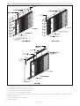
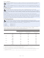
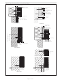
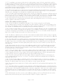
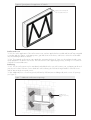
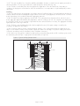
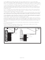
APPROVAL INSPECTION TESTING CERTIFICATION Sto Ltd 2 Gordon Avenue Hillington Park Glasgow G52 4TG Tel: 0141 892 8000 Fax: 0141 404 9001 TECHNICAL APPROVALS FOR CONSTRUCTION Agrément Certificate 95/3132 e-mail: [email protected] website: www.sto.co.uk Product Sheet 1 STO EXTERNAL WALL INSULATION SYSTEMS STOTHERM CLASSIC EXTERNAL WALL INSULATION SYSTEMS PRODUCT SCOPE AND SUMMARY OF CERTIFICATE This Certificate relates to StoTherm Classic External Wall Insulation Systems, comprising expanded polystyrene (EPS) insulation boards with glassfibre reinforcing meshes, render finishes, and featuring three alternative fixing methods, for use on solid masonry and timber- or sheathed light-steelframe constructions on new or existing domestic and nondomestic buildings. AGRÉMENT CERTIFICATION INCLUDES: • factors relating to compliance with Building Regulations where applicable • factors relating to additional non-regulatory information where applicable • independently verified technical specification • assessment criteria and technical investigations • design considerations • installation guidance • regular surveillance of production • formal three-yearly review. KEY FACTORS ASSESSED Strength and stability — the systems can adequately resist wind loads and, in certain applications, impact damage (see section 5). Behaviour in relation to fire — the render finishes have a surface spread of flame classification of B-s2,d0. Depending upon the wall construction the systems are suitable for use on buildings up to 18 m high (see section 6). Risk of Condensation — the insulation systems can contribute to limiting the risk of surface and interstitial condensation (see section 9). Thermal performance — the system can be used to improve the thermal performance of external walls and contribute to meeting the Building Regulations requirements (see section 10). Durability — with appropriate care, the insulation systems should remain effective for at least 30 years (see section 12). The BBA has awarded this Agrément Certificate to the company named above for the product/system described herein. This product/system has been assessed by the BBA as being fit for its intended use provided it is installed, used and maintained as set out in this Certificate. On behalf of the British Board of Agrément Date of First issue: 8 May 2012 Sean Moriarty — Head of Approvals Greg Cooper Originally certificated on 19 October 1995. Energy and Ventilation Chief Executive The BBA is a UKAS accredited certification body — Number 113. The schedule of the current scope of accreditation for product certification is available in pdf format via the UKAS link on the BBA website at www.bbacerts.co.uk Readers are advised to check the validity and latest issue number of this Agrément Certificate by either referring to the BBA website or contacting the BBA direct. British Board of Agrément Bucknalls Lane Garston, Watford Herts WD25 9BA ©2012 Page 1 of 24 tel: 01923 665300 fax: 01923 665301 e-mail: [email protected] website: www.bbacerts.co.uk Regulations In the opinion of the BBA StoTherm Classic External Wall Insulation Systems, if used in accordance with the provisions of this Certificate, will meet or contribute to meeting the relevant requirements of the following Building Regulations (the presence of a UK map indicates that the subject is related to the Building Regulations in the region or regions of the UK depicted): The Building Regulations 2010 (England and Wales) Requirement: A1 Loading Comment: The insulation systems can sustain and transmit wind loads to the substrate wall. See sections 5.8 and 5.14 of this Certificate. Requirement: B4(1) External fire spread Comment: The use of the insulation systems is restricted by this Requirement. See sections 6.1 to 6.6 of this Certificate. Requirement: C2(b) Resistance to moisture Comment: The insulation systems provide a degree of protection against rain ingress. See sections 3.10 and 8.3 of this Certificate. Requirement: C2(c) Resistance to moisture Comment: The insulation systems contribute to minimising the risk of interstitial and surface condensation. See sections 9.1, 9.6 and 9.8 to 9.10 of this Certificate. Requirement: L1(a)(i) Conservation of fuel and power Comment: The insulation systems can contribute to meeting this Requirement. See sections 10.1 and 10.4 of this Certificate. Requirement: Regulation 7 Materials and workmanship Comment: The systems are acceptable. See section 12.1 of this Certificate. The Building (Scotland) Regulations 2004 (as amended) Regulation: 8(1)(2) Regulation: Standard: 9 1.1 2.6 2.7 3.10 3.15 Condensation Walls insulated with the systems will contribute to minimising the risk of interstitial and surface condensation, with reference to clauses 3.15.1(1)(2), 3.15.4(1)(2) and 3.15.5(1)(2). See sections 9.1 and 9.7 to 9.10 of this Certificate. Comment: Standard: Standard: Precipitation Walls insulated with the systems will provide a degree of protection against rain ingress and can provide satisfactory resistance to water penetration, with reference to clauses 3.10.1(1)(2) and 3.10.2(1)(2). See sections 3.10 and 8.3 of this Certificate. Comment: Standard: Spread on external walls The systems incorporate materials which would not be classified as ‘non-combustible’ as defined in this Standard. Completed walls, therefore, should be regarded as unprotected areas, with reference to clause 2.7.1(1)(2). See sections 6.1 to 6.6 of this Certificate. Comment: Standard: Spread to neighbouring buildings The systems incorporate materials which would not be classified as ‘non-combustible’. Completed walls, therefore, should be regarded as unprotected areas as defined in this Standard, with reference to clause 2.6.4(1)(2). See sections 6.1 to 6.6 of this Certificate. Comment: Standard: Building standards — construction Structure The systems can sustain and transmit wind loads to the substrate wall, with reference to clause 6.2(1)(2). See sections 5.8 and 5.14 of this Certificate. Comment: Standard: Fitness and durability of materials and workmanship The use of the systems satisfies the requirements of this Regulation. See sections 11.1 and 12.1 of this Certificate. Comment: 6.1(b) 6.2 Carbon dioxide emissions Buildings insulation envelope The systems can contribute to satisfying these Standards, with reference to clauses 6.1.1(1), 6.1.2(1)(2), 6.1.3(2), 6.1.5(2), 6.1.6(1), 6.2.1(1)(2), 6.2.3(1)(2), 6.2.4(2), 6.2.6(1)(2), 6.2.7(1)(2), 6.2.8(2), 6.2.9(1)(2), 6.2.10(1)(2), 6.2.11(1), 6.2.12(2), and 6.2.13(1). See sections 10.1 and 10.4 of this Certificate. Comment: (1) Technical Handbook (Domestic). (2) Technical Handbook (Non-Domestic). The Building Regulations (Northern Ireland) 2000 (as amended) Regulation: B2 Fitness of materials and workmanship Comment: Regulation: B3(2) Suitability of certain materials Comment: The systems are acceptable. See section 12.1 of this Certificate. The systems are acceptable. See section 11.1 of this Certificate. Page 2 of 24 Regulation: C4(b) Regulation: C5 D1 E5(a) External fire spread The use of the insulation systems is restricted by this Requirement. See sections 6.1 to 6.6 of this Certificate. Comment: Regulation: Regulation: Stability The insulation systems can sustain and transmit wind loads to the substrate wall. See sections 5.8 and 5.14 of this Certificate. Comment: Regulation: Condensation Walls insulated with the systems contribute to minimising the risk of interstitial condensation to satisfy this Regulation. See sections 9.1 and 9.8 to 9.10 of this Certificate. Comment: Regulation: Resistance to ground moisture and weather Walls insulated with the systems provide a degree of protection against rain ingress and therefore contribute to satisfying this Regulation. See sections 3.10 and 8.3 of this Certificate. Comment: F2(a)(i) F3(2) Comment: Conservation measures Target carbon dioxide Emissions Rate The insulation systems can contribute to satisfying these Regulations. See sections 10.1 and 10.4 of this Certificate. Construction (Design and Management) Regulations 2007 Construction (Design and Management) Regulations (Northern Ireland) 2007 Information in this Certificate may assist the client, CDM co-ordinator, designer and contractors to address their obligations under these Regulations. See section: 2 Delivery and site handling (2.4) of this Certificate. Additional Information NHBC Standards 2011 NHBC accepts the use of StoTherm Classic External Wall Insulation Systems, when installed with a cavity and used in accordance with this Certificate, in relation to NHBC Standards, Part 6 Superstructure (excluding roofs), Chapters 6.9 Curtain walling and cladding and 6.10 Light steel framed walls and floors. General This Certificate relates to StoTherm Classic External Wall Insulation Systems, as applied to the outside of external walls of masonry, dense or no-fines concrete on new or existing domestic and non-domestic buildings. They can also be installed onto timber- or sheathed lightweight-steel-framed structures where the steel frame forms the primary structure for the building. For timber-framed constructions, a breather membrane must be secured to the sheathing and an appropriate cavity created with a nominal width of 20 mm. Where required, for installations onto lightweight steel-framed walls, Sto Mechanical systems should be installed with the appropriate drainage cavity. In some applications not requiring NHBC Approval, or where water ingress will not cause damage to the wall construction, the systems can be applied directly to an appropriately rigid (see section 5.13), sheathed light steel frame. For these applications the insulation systems must be fixed and restrained in exactly the same way as they would be if fixed back to a masonry substrate. The building designer must ensure that moisture cannot enter the wall construction and that resistance to moisture is maintained throughout the design life of the facade (see sections 8 and 9). The insulation systems are manufactured by Sto AG in Germany and are imported and marketed in the UK by the Certificate holder. Technical Specification 1 Description 1.1 StoTherm Classic External Wall Insulation Systems (see Figure 1) are of three types: • StoTherm Classic Rotofix Plus Mechanical insulation systems — tongue-and-groove expanded polystyrene (EPS) boards of size 1000 mm by 500 mm(1)(2), fixed to the substrate with a fixing incorporating a rotating spiral loadtransfer plug and the relevant supplied fixing pin. The fixing is embedded into the insulation and the helical shape allows for adjustment to be made to the plane of the surface of the insulation boards. There are two types of fixings, depending on the cavity width required (see Table 1). (1) Information on other board sizes can be obtained from the Certificate holder. (2) The tongues and grooves must be at least 12 mm wide and 15 mm deep and at least 17.5 mm from the board edge. Page 3 of 24 Table 1 Sto Rotofix Plus fixing and desired cavity width Fixing Cavity width (mm) Sto Rotofix Plus Green 120T/E1 10 to 30 10 to 70 Sto Rotofix Plus Black 160T/E100 (1) (1) Not suitable for use with insulation <130 mm unless the cavity width is >30 mm (see Certificate holder for details). • StoTherm Classic Mechanical insulation systems (M) — grooved/slotted expanded polystyrene (EPS) boards of size 500 mm by 500 mm(1), fixed to the substrate with an unplasticised polyvinyl chloride (PVC-U) or aluminium track system comprising horizontal starter tracks, intermediate tracks, intermediate tracks cut and fixed into vertical board joints, and PVC packers. Starter and holding tracks are fastened to substrates with Sto-approved hammer-drive or screw fixings • StoTherm Classic Adhesive insulation systems (K) — square-edge or tongue-and-groove insulation boards of size 1000 mm by 500 mm(1)(2), bonded to the substrate (with a minimum of 40% adhesive coverage and supplementary mechanical fixings(3)) using one of: — StoLevell Uni — a polymer-based powder adhesive containing cement for mixing with clean water — Sto Baukleber ADH B — a powder adhesive containing cement for mixing with clean water — Sto dispersion adhesive — a ready-to-use organically-bound adhesive for level substrates — Sto Turbofix(4) — a single-component polyurethane foam adhesive for use with EPS insulation. (1) Information on other board sizes can be obtained from the Certificate holder. (2) The tongues and grooves must be at least 12 mm wide and 15 mm deep and at least 17.5 mm from the board edge. (3) Details of the use of the systems without supplementary fixings can be obtained from the Certificate holder. (4) For use with EPS with a tensile strength of 150 kPa, shear strength of >0.02 N·mm–2 and shear modulus of >1 N·mm–2. 1.2 Three types of expanded polystyrene insulation boards are used with the systems (see Table 2). The boards are classified as Euroclass E in relation to fire, in accordance with BS EN 13501-1 : 2007. Each pack is marked with the manufacturer’s name and each board with a coloured stripe indicating the grade and fire classification. Table 2 EPS types Type Density (kg·m–3) Tensile strength (kPa) Shear strength (N·mm–2) Shear modulus (1 N·mm–2) Thickness(1)(2) (mm) K90(3)(4) 19–20 150 >0.02 >1 20–200 K70 16–17 100 >0.02 >1 20–200 (5) (1) (2) (3) (4) In 10 mm increments. Thicknesses < 60 mm are for use in areas such as window reveals. Available in white and grey. 100 mm to 200 mm thickness for use with the StoTherm Classic Rotofix Plus Mechanical insulation systems, StoTherm Classic Mechanical insulation systems (M) and the StoTherm Classic Adhesive insulation systems (K). (5) 60 mm to 200 mm thickness for use with the StoTherm Classic Adhesive insulation systems (K). 1.3 The systems have not been assessed for use below the dpc. 1.4 Other components of the systems include: • Sto Glass Fibre Mesh — multi-stranded, alkali-resistant glassfibre with a polymer coating, marked with the Sto logo and weighing approximately 150 g·m–2, supplied in rolls 1.1 m wide by 50 m in length • StoArmor Mesh — used in conjunction with Sto Glass Fibre Mesh, marked with the Sto logo and weighing approximately 490 g·m–2 • StoArmat Classic — a ready-mixed, polymer-based ground coat and reinforcing plaster • Stolit — a ready-mixed, acrylic-based, textured coating • StoSilco — a ready-mixed, silicone-based, textured coating • StoSilco MP — a ready-mixed, silicone-based, textured coating or receiver for dry-dash finish • StoLotusan — a ready-mixed, silicone-based, textured coating • Sto Dash Finish — a spar-dash aggregate (3 mm to 6 mm) for use with StoSilco MP • StoColor Maxicryl, StoColor Crylan, StoSilco Color, StoLotusan Color and StoColor Jumbosil — acrylic or siliconebased paints available in a range of colours • Sto Primer — an acrylate-copolymer-based tinted primer used as a bonding agent and pre-coat to control suction. Page 4 of 24 Figure 1 StoTherm Classic External Wall Insulation Systems 1.5 Ancillary items for use with the systems are: • Sto aluminium starter/intermediate fixing track • Sto PVC-U starter/intermediate fixing track • Sto T spline, PVC or aluminium T-profiles • PVC packing shims of varying sizes used to ensure the level of the finished surface and maintain the drainage cavity • Sto Rotofix Plus fixing • Sto mineral fibre fire-break boards • StoPrim Fungal Page 5 of 24 • • • • • • • • • • • • • • • • StoPlex W sealer StoPrim Micro sealer Sto PVC Mesh Angle Bead Sto detail mesh StoArmour Angle Sto Movement Joint Type E Sto Movement Joint Type V StoSeal Tape Sto PU foam filler StoDeco Profiles (recycled mineral granulate profiles for architectural details) StoDeco Coll Adhesives for StoDeco Profiles SS hammer drive fixings Sto fixings deflection channels for deflecting water around openings drainage profiles to allow the drainage of water from the cavity to the external face of the wall, where required Sto F505 sealant. 1.6 Quality control checks are carried out on the incoming materials, during production and on the finished product. 2 Delivery and site handling 2.1 The insulation boards are delivered in shrink-wrapped polythene packs, bearing the Sto logo, manufacturer’s name and product identification. Each board is identified with a coloured stripe indicating the grade and fire classification. 2.2 The insulation boards must be stored on a clean, firm, level base and protected from prolonged exposure to sunlight. Open packs should be protected either by storing under cover or re-covering with opaque polythene sheeting. The boards must not come into contact with solvents or bitumen products, nor be exposed to open flame or other ignition sources. Care must be taken when handling the insulation to avoid damage. Damaged insulation boards should be separated and not used. 2.3 All bagged products should be stored in dry conditions, off the ground, and protected from moisture. All render products must be protected from excessive heat and frost. 2.4 Components are delivered in the containers and quantities listed in Table 3. Each container carries the product identification. Table 3 Component supply details Component Packaging and quantity/size Standard reinforcing mesh roll, 1.1 m by 50 m Sto Armor mesh roll, 1 m by 25 m Sto TurboFix adhesive pressurised bottle, 10.4 kg and 750 ml can Sto cementitious adhesive triple-lined bag, 20–25 kg Coatings pail, 15 litre Primer/cement-free reinforcing coats and renders plastic pail, 23–25 kg 2.5 Sto Turbofix adhesive should be stored at temperatures between 15°C and 25°C. Assessment and Technical Investigations The following is a summary of the assessment and technical investigations carried out on StoTherm Classic External Wall Insulation Systems. Design Considerations 3 General 3.1 The StoTherm Classic External Wall Insulation Systems are applied to the outside of external walls of masonry and dense or no-fines concrete constructions and timber or light-steel-framed constructions. They are suitable for use on new or existing domestic and non-domestic buildings one metre or more (more than one metre in Scotland) from a boundary and where the floor level of any storey above the ground floor is not higher than 18 m above ground level. 3.2 The systems are fixed to the external surface of the wall using the mechanical systems or adhesive. The Sto EPS boards are protected by a minimum 3 mm thick reinforcement coat of StoArmat Classic containing a glassfibre reinforcement mesh which, when dry, is overcoated with one of the finishes listed in section 1.4. Should a dash finish be required, application can only be made over StoSilco MP applied in a thickness of between 5 mm and 6 mm. Page 6 of 24 Steel-framed buildings 3.3 When mechanically-fixed insulation systems are used on steel-framed buildings incorporating vertical steel studs (minimum thickness 1.2 mm, minimum flange width 50 mm, fixed at a maximum of 600 mm centres) and sheathed with a fire-rated, exterior-grade sheathing board (see Table 3), the insulation systems are secured to the sheathing board creating a cavity between the sheathing and insulation. For new build domestic constructions intended to be covered by NHBC guarantee, a drained cavity of nominal 20 mm width must be provided. Timber-framed buildings 3.4 Timber-framed buildings should be sheathed and designed in accordance with BS EN 1995-1-1 : 2004 and BS EN 1995-1-2 : 2004 (Eurocode 5). The system must incorporate an appropriate 20 mm (nominal) wide vented and drained cavity. 3.5 The minimum specification of sheathed steel-framed construction on which the insulation systems can be installed is given in Table 4. Table 4 Sheathed steel-framed construction — minimum specification Item Steelwork Sheathing board (fire-rated) Characteristic Standard or dimension (mm) Standard Grade and coating Thickness BS EN 10326 : 2004 Type S 320 GD +Z275 1.2 Type Thickness BS EN 634-2 : 2007 12 3.6 Mechanical fixings are used with the Sto Mechanical system and supplementary mechanical fixings are used with the adhesive insulation systems, especially during the strength development phase of the adhesive curing. Care should be taken to ensure appropriate fixing on all substrates. The Certificate holder can give guidance on the use of the systems without mechanical fixings. 3.7 The systems are effective in reducing the thermal transmittance (U value) of the walls in new and existing buildings. It is essential that the detailing techniques specified in this Certificate are carried out to a high standard if the ingress of water into the insulation is to be avoided and the full thermal benefit obtained from the insulation systems. 3.8 The systems will improve the weather resistance of a wall and provide a decorative finish. However, they may only be installed where other routes for moisture penetration have been dealt with separately, and effectively, and where there are no signs of dampness on the inner surface of the inner leaf of the wall, other than those caused by condensation. The systems can be used to overcome condensation associated with the internal wall surface. 3.9 Buildings should have wall surfaces in accordance with section 14 Site survey and preliminary work in the Installation part of this Certificate. 3.10 New walls subject to the national Building Regulations and other new buildings not subject to regulatory requirements should be constructed in accordance with the relevant recommendations of: • • • • BS BS BS BS EN 1996-1-1 : 2005, BS EN 1996-1-2 : 2005, BS EN 1996-2 : 2006 and BS EN 1996-3 : 2006 5628-3 : 2005, with particular reference to Clause 5.5 Exclusion of water EN 1993-1-1 : 2005 (Eurocode 3)(1), and the relevant parts of this Certificate 8000-3 : 2001. (1) And other parts where appropriate. 3.11 It is essential that movement joints are used through the insulation systems to ensure all substrate movement is not transferred to the insulation system and is managed in a such a way that damage to the insulation systems does not occur. Designers must ensure the sheathing boards are adequately restrained, an appropriate number of movement joints are used carried through the construction where required. 3.12 When using the systems, consideration must be given to the overall design to minimise the risk of condensation and the recommendations of BS 5250 : 2011 should be followed. 3.13 The fixing of rainwater goods, satellite dishes, clothes lines, hanging baskets and similar items is outside the scope of this Certificate. 3.14 The effect of installation of the system on the acoustic performance of a construction is also outside the scope of this Certificate. 3.15 It is essential that the insulation systems are installed and maintained in accordance with the conditions set out in this Certificate. 4 Practicability of installation The systems should only be installed by installers who have been trained and registered with the Certificate holder (see section 13). Page 7 of 24 5 Strength and stability General 5.1 The systems can be designed to provide adequate resistance to design wind loads applicable in the UK. The actual resistance to wind loads will depend upon the wall construction and insulation system used. 5.2 Provided the substrate is suitable (see section 3.5), the fixings will effectively transfer the self-weight of the render insulation systems to the substrate. 5.3 The self-weight of the insulation systems including the render and the insulation is transferred to the substrate via the relevant fixing method. The number and the span between rail fixings, the number and span between Rotofix Plus fixings or the suitability of adhesive should be determined by the building designer. 5.4 Where either of the mechanical fixing systems is used, the condition of the surface to receive the product is not a consideration provided the fastenings are anchored into a substrate capable of supporting the loads imposed by the external insulation plus the forces acting upon it. Trial tests shall be conducted on the walls of the building (see section 5.11). 5.5 Where the adhesive insulation system is used, trial tests shall be conducted on the walls of the building to determine the adequacy of the adhesive to withstand the expected wind loading (derived from calculations using the relevant wind speed data for the site) and a safety factor of 9. A recommendation is made on the type and number of fixings required to complement the adhesive mortar to withstand the wind loading(1) (see section 5.11). (1) Details of the use of the systems without supplementary fixings can be obtained from the Certificate holder. 5.6 Negative wind pressure (suction) is resisted by the bond between the render and the insulation boards, the flexural strength of the render and insulation and, depending upon the chosen fixing method, one of: • StoTherm Classic Rotofix Plus Mechanical insulation systems — the resistance to pull-over of the fixing from the insulation, the strength of the Rotofix Plus fixing and the resistance to pull-out between the fixing and substrate wall • StoTherm Classic Mechanical insulation systems (M) — the resistance to pull-over of the rail from the insulation, the strength of the rail, the resistance to pull-over of the rail from the rail fixing and the resistance to pull-out between the fixing rail and substrate wall • StoTherm Classic Adhesive insulation systems (K) — the adhesive bond strength between the insulation and the adhesive and the adhesive bond strength between the adhesive and substrate. 5.7 Positive wind load (pressure) is transferred to the substrate wall directly via compression and bending of the render and insulation and, depending upon the chosen fixing method, one of: • StoTherm Classic Rotofix Plus Mechanical insulation systems — the bearing of the insulation onto the substrate or the flexural strength of the render and insulation through the fixings and into the substrate wall • StoTherm Classic Mechanical insulation systems (M) — the bearing of the insulation onto the substrate or the flexural strength of the render and insulation through the fixing rails and packers where used and into the substrate wall • StoTherm Classic Adhesive insulation systems (K) — the bearing of the insulation through the adhesive into the substrate. 5.8 The wind loads on the walls should be calculated in accordance with BS EN 1991-1-4 : 2005 or BS 6399-2 : 1997. Special consideration should be given to locations with high wind-load pressure coefficients (additional fixings or adhesive coverage may be necessary). In accordance with BS EN 1990 : 2002, it is recommended that a load factor of 1.5 is used to determine the ultimate wind load to be resisted by the insulation systems. 5.9 The bond between the reinforcement coat and insulation is adequate to resist negative pressures likely to occur in buildings in the UK. 5.10 Assessment of structural performance for individual buildings shall be carried out by a suitably qualified engineer or other appropriately qualified person to confirm that: • the substrate wall has adequate strength to resist the additional loads that may be applied as a result of installing the insulation systems, ignoring any positive contribution that may occur from the insulation systems • the proposed insulation system and associated fixing layout or adhesive provide adequate resistance appropriate to the thickness of insulation used and the negative wind loads (based on the results of the site investigation). 5.11 The determination of the resistance to wind loads depends upon the fixing system used (see Table 5): • StoTherm Classic Rotofix Plus Mechanical insulation systems — tests carried out on an installation with tongue-andgroove insulation boards with a minimum of four and a minimum of six fixings per square metre indicated that the systems can resist wind loads of 1500 Pa and 2500 Pa respectively • StoTherm Classic Mechanical insulation systems (M) — tests carried out on an installation with horizontal rails fixed at a maximum of 300 mm centres indicated that the system can resist a wind load of 1300 Pa. Page 8 of 24 Table 5 Sto external wall insulation systems — example wind loading calculations (1) Characteristic Resistance to wind loads (Pa)(1) StoTherm Classic Rotofix Plus Mechanical insulation systems (4 fixings) StoTherm Classic Rotofix Plus Mechanical insulation systems (6 fixings) StoTherm Classic Mechanical insulation systems (M) StoTherm Classic Adhesive insulation systems (K) 2300 3900 3900 — Material factor 1.5 1.5 3 — 1533 2600 1300 — 800 800 650 10000 2 2 2 9 Design pull out resistance or design adhesive bond strength (N) 400 400 325 1111 Design pull out resistance multiplied by the number of fixings (N) 1600 2400 1950 — Limiting resistance (Pa)(4) 1533 2400 1300 2222 (2) Design resistance to wind loads(Pa) Characteristic anchor pull-out resistance per anchor or adhesive bond strength (N)(3) Factor of safety (1) (2) (3) (4) From test results (see section 5.11). Based upon the EPS used and the manufacturing controls in place. From site tests (see section 5.12). The lesser of the board design pull out resistance and the resistance to wind loads for the system. This value must be higher than the value calculated from section 5.8 (see section 5.12). 5.12 An appropriate number of site-specific pull-out tests shall be conducted on the substrate of the building (masonry, concrete or plain sheathing board) to determine the minimum resistance to failure of the fixings. The characteristic pullout resistance should be determined in accordance with the guidance given in ETAG 014 : 2002, Annex D, using 60% of the mean value of the five smallest measured values at the ultimate load. The design pull-out resistance per square metre is the mean pull-out resistance multiplied by the number of fixings (minimum of either 4 or 6) and divided by a factor of safety of 2. This value must be higher than the resistances given in section 5.11. 5.13 For the StoTherm Classic Adhesive insulation systems (K), an appropriate number of site-specific bond strength tests should be conducted on the substrate of the building to determine the minimum resistance to failure of the adhesive. The design bond strength is the average of the five smallest measured values at the ultimate load divided by a factor of safety of 9. 5.14 The mechanical insulation systems are not affected by the maximum deflections permitted in the design of steel-frame structures to BS EN 1993-1-1 : 2005 and BS 5950-5 : 1998, ie span/300. Mid span deflections should not be greater than span/300. Deflection should be limited where possible to minimise damage to the insulation systems. 5.15 It is essential that the appropriate movement joints are incorporated into the construction to accommodate the differential movement, for example, movement and contraction due to variation of temperature and moisture content. This is to ensure substrate movement does not damage the insulation system. 5.16 The designer should ensure that firebreaks used with the system are fixed adequately to resist the anticipated wind loading. Impact loading 5.17 The systems are suitable for use 1.5 m above pedestrian or floor level in areas accessible primarily to those with a high incentive to exercise care or areas with only a small chance of accidents or misuse occurring (location category C as defined in BS 8200 : 1985, Table 2). For areas likely to be prone to greater impacts, the advice of the Certificate holder should be sought. 6 Behaviour in relation to fire General 6.1 The surface spread of flame classification of the external surface of the system is given in Table 6. Table 6 Surface spread of flame performance (1) Maximum declared organic content of the rendering system(2) Reinforcement coat: 16% Finishing coat: 14.75% Minimum declared flame retardant of the rendering system(2) Euroclass according to BS EN 13501-1 : 2007 Reinforcement coat: 20% Finishing coats: 7.5% B-s2,d0 (1) The effects of primer and paint need to be taken into account by the building designer. (2) Percentage relative to the initial weight after drying. Page 9 of 24 6.2 The designer should check the fire ratings which apply to the system (including paint and primer) to be used. 6.3 The insulation material is combustible and therefore its use is restricted by the building regulations. 6.4 Insulation systems are restricted for use in buildings less than 18 m in height unless they are designed in accordance with BRE Report (BR 135 : 2003) Fire Performace of External Insulation For Walls of Multi-Storey Buildings. 6.5 The fire-resistance performance of a wall incorporating the systems is outside the scope of this Certificate. Where required, this can only be determined from tests performed by a UKAS accredited laboratory for the test concerned. 6.6 Fire stopping or fire barriers should be incorporated into a construction where required by the relevant building regulations. 7 Proximity of flues and appliances When the insulation systems are installed in close proximity to certain flue pipes, the relevant provisions of the national Building Regulations should be met: England and Wales — Approved Document J Scotland — Mandatory Standard 3.19, clause 3.19.4(1)(2) (1) Technical Handbook (Domestic). (2) Technical Handbook (Non-Domestic). Northern Ireland — Technical Booklet L. 8 Rain penetration 8.1 Guidance in BRE Report (BR 262 : 2002) Thermal insulation : avoiding risks should be followed in that the designer should select a construction appropriate to the local wind-driven rain index, paying due regard to the design detailing, workmanship and materials to be used. Additional guidance can be found in: England and Wales — Approved Document C, Section 5 Scotland — Mandatory Standard 3.10, clauses 3.10.1(1)(2) and 3.10.2(1)(2) (1) Technical Handbook (Domestic). (2) Technical Handbook (Non-Domestic). Northern Ireland — Technical Booklet C, Section 2. 8.2 The systems have been assessed for use in sheltered areas when installed onto light steel framework. 8.3 In all cases, care should be taken to ensure that walls are weathertight prior to application of the insulation systems. The insulation systems shall only be installed where there are no signs of dampness on the inner surface of the substrate other than those caused solely by condensation. 8.4 Where used, the sheathing board substrate shall be of a suitable exterior grade with appropriately sealed joints, sealed penetrations and vapour control layers where required. Examples of relevant detailing for external wall insulation systems with a drainage cavity can be seen in SCI Publication P343 Insulated Render Systems Used With Light Steel Framing, Steel Construction Institute, 2006. 8.5 Additional measures shall be taken when the system is directly fixed to a sheathing board to ensure water penetration does not occur. The designer should check that the windows, doorsets, flashings, and other similar items have been specifically designed for this use. Particular attention should be paid to the prevention of water ingress. For example, at junctions between the insulation systems and windows, openings and penetration details should be designed to deflect water away from the insulation and onto the external face of the wall. 8.6 Dynamic modelling of moisture transfer should be carried out in accordance with BS EN 15026 : 2007, especially for light steel framed constructions to help establish the likelihood of moisture accumulating within the construction over the design life of the building. 8.7 At the tops of walls, the insulation systems should be protected by an adequate overhang or other detail designed for use with this type of insulation systems (see section 15.43). 9 Risk of condensation 9.1 When using the systems, consideration must be given to the overall design to minimise the risk of condensation, and the recommendations of BS 5250 : 2011 should be followed. Designers should ensure that an appropriate condensation risk analysis has been carried out for all parts of a construction, including at junctions between the insulation systems and windows, between the adhesive (where applicable) and sheathing board or elsewhere on the steel frame, and at other openings and penetrations to ensure condensation does not occur at the surface or within. This should take into consideration the effect of any cavities included within the construction. 9.2 Dynamic modelling of the condensation risk should be carried out to help establish the likelihood of moisture accumulating within the construction over the design life of the building. See section 8.6. 9.3 The water vapour resistivity for the base coat with the render finishes is not more than 2000 MN·s·g–1·m–1. 9.4 The resistivity of the EPS insulation boards can be taken as 300 MN·s·g–1·m–1. 9.5 Internal wet work, eg screeding or plastering, shall be completed and all the construction moisture be allowed to dry prior to application of the systems. Page 10 of 24 Surface condensation 9.6 Walls will adequately limit the risk of surface condensation when the thermal transmittance (U value) does not exceed 0.7 W·m–2·K–1 at any point, and the junctions with other elements and openings comply with section 10.4. 9.7 Walls will adequately limit the risk of surface condensation when the thermal transmittance (U value) does not exceed 1.2 W·m–2·K–1 at any point. See BS 5250 : 2011, Section 8, and BRE Report (BR 262 : 2002) for additional information. Interstitial condensation 9.8 Weathertight walls incorporating the insulation systems will adequately limit the risk of interstitial condensation when they are designed and constructed in accordance with BS 5250 : 2011, Section 8 and Annex D. Care shall be taken to ensure the building is adequately sealed (and remains adequately sealed) and ventilation is in place to help prevent condensation forming on the internal face of the sheathing board or the surface of the steel frame. 9.9 If the insulation systems are to be used on the external walls of rooms expected to have continuous high humidities, care shall be taken in the design of the rooms to avoid the formation of surface and interstitial condensation. 9.10 A wall shall be constructed to have resistance against water vapour ingress. The incorporation of a cavity within a construction will help any water vapour reaching the cavity to dissipate. The designer should make provision for this, ensuring that any condensate which may form can drain freely to the outside of a wall construction. 10 Thermal performance 10.1 Calculations of the thermal transmittance (U value), including the effect of any cavity within the construction, should be carried out in accordance with BS EN ISO 6946 : 2007, BRE Report (BR 443 : 2006) Conventions for U-value calculations, and, where required, BRE Digest (BR 465 : 2002) U-values for light steelframe construction, using the declared thermal conductivity (90/90 value) (W·m–1·K–1) of: • K70 EPS • K90 EPS • K90 EPS grey 0.038 W·m–1·K–1 0.034 W·m–1·K–1 0.030 W·m–1·K–1. 10.2 The U value of a wall construction will depend on the selected insulation thickness, the fixing method and the insulating value of the substrate and its internal finish. Example U values are given in Tables 7 and 8. Table 7 Insulation thickness required to achieve some typical design values (1) U value (Wm–2·K–1) Insulation type 0.19 Thickness of insulation (mm) StoTherm Classic Rotofix Plus Mechanical insulation systems (2)(3)(4) StoTherm Classic Mechanical insulation systems (M) (2)(4)(5)(6) StoTherm Classic Adhesive insulation systems (K) (2)(7) K70 K90 K90 grey — 230 210 — 170 150 210 190 170 0.26 K70 K90 K90 grey — 150 140 — 120 110 150 140 120 0.28 K70 K90 K90 grey — 140 120 — 110 100 140 130 110 0.30 K70 K90 K90 Grey — 120 110 — 100 90 120 110 100 0.35 K70 K90 K90 Grey — 100 90 — 90 80 100 90 90 (1) (2) (3) (4) (5) (6) Based on an uninsulated wall U value of 2.1 W·m–2·K–1 construction. Actual U value for the thickness may be better, based upon incremental insulation thickness of 10 mm. Rotofix fixings = 6 per square metre. The point of thermal transmittance of the Rotofix Plus fixing can be taken as 0.009 W·m–1·K–1. Includes 10 mm unventilated cavity (in accordance with BS EN ISO 6946 : 2007). Includes one 8 mm diameter stainless steel fixing where nf = 1 per square metre ( = 17 W·m–1·K–1).per square metre, ⌬Uf < 3% of U. ⌬Uf < 3% of U for the PVC fixing rail. The effect of the aluminium fixing rail is greater than 3% of the U value and should be calculated depending upon the insulation thickness used. (7) ⌬Uf based on nf = 4 m–2, steel = 50 W·m–1·K–1, diameter of fixing = 5.5 mm (assumes that the fixing penetrates the whole insulation layer). Page 11 of 24 Table 8 Steel frame — approximate wall U values (1)(2)(3) U value (W·m–2·K–1) StoTherm Classic Rotofix Plus Mechanical insulation systems StoTherm Classic Mechanical insulation systems (M)(6) StoTherm Classic Adhesive insulation systems (K)(7) 0.19 180(5) 170 200 0.26 120(5) 120 140 0.28 110 (4) 110 130 0.30 110(4) 110 120 0.35 100 100 100 (4) (1) Wall construction: • 12.5 mm plasterboard ( = 0.25 W·m·–1·K–1) • 150 mm steel C-sections 1.2 mm thick with 50 mm flanges ( = 50 W·m·–1·K–1) • 12 mm cement particle board ( = 0.23 W·m·–1·K–1) • 20 mm cavity spacer ( = 0.17 W·m·–1·K–1) • 15 mm unventilated cavity (BS EN ISO 6946 : 2007) • Rail fix system only – PVC fixing rail ( = 0.17 W·m·–1·K–1) • number Rotofix fixings = 6 m–2 • 5 mm diameter steel anchor ( = 50 W·m·–1·K–1) • EPS insulation ( = 0.038 W·m·–1·K–1) • 8 mm render ( = 1 W·m·–1·K–1) • as may be required for the building regulations, one 8 mm diameter stainless steel fixing, nf = 1 m2 ,( = 17 W·m·–1·K–1). (2) U value for the plain wall element only. (3) Three-dimensional computer modelling in accordance with BS EN ISO 10211 : 2007. (4) Rotofix green. (5) Rotofix black. (6) The effect of PVC fixing rail is less than 3% of the U value. The effect of the aluminium fixing rail is greater than 3% of the U value and should be calculated depending upon the insulation thickness used. (7) K 70 EPS. 10.3 When considering insulation requirements, designers should refer to the detailed guidance given in documents supporting the national Building Regulations. 10.4 The systems can maintain, or contribute to maintaining, continuity of thermal insulation. Care must be taken to ensure an appropriate thickness of insulation is used, particularly at points such as junctions between floors and walls and at window and door reveals, to avoid thermal bridging and reduce the risk of condensation forming at these points. Items such as windows and doors should be selected taking into account the thickness of insulation required at the reveals to help prevent condensation forming at these junctions. Detailed guidance for junctions and on limiting heat loss by air infiltration can be found in: England and Wales — Approved Documents to Part L and, for new thermal elements to existing buildings, Accredited Construction Details (version 1.0) (for new-build, see also SAP 2009, Appendix K, and the iSBEM User Manual) Scotland — Accredited Construction Details (Scotland) Northern Ireland — Accredited Construction Details (version 1.0). 11 Maintenance and repair 11.1 Regular checks must be made on the installed insulation systems. Particular attention should be made to joints with other elements and seals to ensure that ingress of water does not occur. The checks should verify that architectural details for shedding water clear of the building are present and functioning, and that external plumbing fitments are in good condition. Maintenance schedules should include the replacement and resealing of joints, for example between the insulation systems and window and door frames. The interval between inspections should be considered for each building allowing for such factors as the wall construction, building location and height. Systems that are directly fixed back to sheathing boards must be inspected at least once per year. Necessary repairs should be effected immediately and the sealant at joints at window and door frames replaced at regular intervals. 11.2 The designer should ensure suitable access is available to enable maintenance inspections to take place safely. 11.3 Damaged areas must be repaired using the appropriate Sto components and the procedures detailed in the Certificate holder’s technical literature. The Certificate holder should be consulted on the appropriate measures for a particular installation. 11.4 The finishes may become soiled in time, the rate depending on the product chosen, initial colour, the degree of exposure, level of atmospheric pollution and the design and detailing of the wall. The appearance may be restored by a powerwash at 30 bar maximum pressure and 30°C maximum temperature or, if required, overcoating by the application of a further finish of paint, but great care must be taken not to adversely affect the water vapour transmission characteristics or fire properties of the insulation systems. 12 Durability 12.1 The systems should remain effective for at least 30 years, provided any damage to the surface finish is repaired immediately, and regular maintenance is undertaken (see section 11). Page 12 of 24 12.2 The standard reinforcing mesh has adequate resistance to accidental damage where used in situations where walls are exposed but have some protection, eg walls of private dwellings and walls of communal dwellings above ground-floor level. In other situations, eg walls of public buildings at ground-floor level, the combined heavy duty and standard reinforcing meshes are required to increase the resistance to impact. Guidance may be obtained from BRE Current Paper CP 6/81 : 1981 Assessment of external walls — Hard body Impact Resistance, and the Certificate holder. Installation 13 General Application of StoTherm Classic External Wall Insulation Systems, should be carried out by registered installers as recommended by the Certificate holder. A Certificate-holder registered installer is a company which: • employs operatives who have been trained by the Certificate holder to install the insulation systems and who, upon completion of their training, have been issued with an appropriate identification card or certificate by the Certificate holder • has undertaken to comply with the Certificate holder’s application procedure, including the requirement for each application team to include at least one member with an identification card or training Certificate • is subject to audits by the Certificate holder, including site inspections. 14 Site survey and preliminary work 14.1 It is essential that the substrate is weathertight before the installation of the insulation systems. A pre-installation survey of the property shall be carried out to determine whether repairs are required to the building structure, sheathing board or steel frame. The survey shall include tests and an assessment and recommendation on the type and number of fastenings required in respect of the building’s expected wind loading. The installer shall prepare a specification for each project, in accordance with the Certificate holder’s requirements, covering each elevation of the building, and with details indicating: • position of tracks • number and fixing pattern for Sto Rotofix Plus fixings • position of starter profile or starter mesh • reinforcing mesh(es) (for adhesively fixed insulation systems) • detailing around windows, doors and at eaves • dpc level • exact position of movement joints, if required • areas where exterior grade sealants must be used • location and type of weather seals to be used • location of water deflection channels (see Figure 11) • alterations required to external plumbing • position of fire barriers. 14.2 The suitability of the construction for the installation of the insulation systems shall be determined as part of the pre-installation survey. 14.3 All necessary repairs to the building structure shall be completed before installation of the insulation systems commences. 14.4 Surfaces shall be sound, clean, and free from loose material. The flatness of surfaces shall be checked and any excessive irregularities made good prior to installation to ensure that the insulation boards are installed with a smooth, in-plane finished surface. 14.5 Where surfaces are covered with an existing rendering, it is essential that the bond between the background and the render is adequate. All loose areas shall be hacked off and reinstated appropriately and adequately. If the adhesive bond strength is determined not to be sufficient, one of the mechanical fixing systems should be used with a supplementary adhesive. 14.6 On existing buildings, purpose-made sills shall be fitted to extend beyond the finished face of the insulation systems. New buildings shall incorporate suitably deep sills. 14.7 Where appropriate, external plumbing shall be removed and alterations made to underground drainage to accommodate its repositioning on the finished face of the insulation systems. 14.8 Internal wet work, eg screeding or plastering, shall be completed and allowed to dry prior to the application of the insulation systems. 15 Procedure General 15.1 Application of StoTherm Classic External Wall Insulation Systems is carried out in accordance with the Certificate holder’s instructions. 15.2 Application of coating materials shall not be carried out on damp substrates, if rain is expected, at temperatures below 5°C or above 30°C, or if exposure to frost is likely. The coating shall be protected from rapid drying. Weather conditions, therefore, should be monitored to ensure correct curing conditions. 15.3 All rendering should be in accordance with the relevant recommendations of BS EN 13914-1 : 2005. 15.4 Insulation boards can be cut on site using a fine-toothed saw or a hot wire cutter. Care must be taken to ensure the surface of the insulation boards is not damaged. See Certificate holder for details. Page 13 of 24 Movement joints 15.5 Movement joints should be included where required. For example, if a movement joint is incorporated in the substrate, a movement joint must be provided in the insulation systems. 15.6 Movement joints extend through the full insulation systems and are made using Sto profiles E or V (see Figure 2), or sealed with an movement joint sealant against a backer rod(1). (1) The Certificate holder can advise on suitable sealants and backer rods. Figure 2 Movement joints movement joint in substrate intermediate track expansion joint mineral quilt to prevent cold bridge expansion joint corner joint (Type V) in-line joint (Type E) 15.7 Where necessary, movement beads are fixed vertically in predetermined positions across the building depending on the individual requirements of each job. 15.8 The movement joint sealant shall not come into direct contact with the insulation board. Therefore, it is essential to ensure that the reinforcement mesh and the reinforcement coat are taken around the complete edge of the insulation board. StoTherm Classic Rotofix Plus Mechanical insulation systems 15.9 For Sto Rotofix Plus mechanical system installations beginning at the base of the wall, the Sto aluminium horizontal starter track is used to mount the first row of boards. For installations commencing at first-floor level either the Sto aluminium starter track or a temporary timber batten may be used. The aluminium profiles are fixed to the substrate with Sto hammer-drive fixings or screws with a fixing at each end of the track (fixings must accommodate the thermal expansion of the track) at maximum of 300 mm centres (see Figure 3). Care shall be taken not to overdrive the fixings. The insulation boards are installed with the tongue edges of the insulation boards aligned to the top and left of the board. 15.10 If a temporary timber batten is to be used, a strip of mesh is partially adhered to the wall so that 200 mm plus the thickness of the insulation is hanging from the starting line of the insulation. The cavity must be filled using PU foam at the base to fill the gap (the excess foam must be trimmed away). StoArmat Classic is used to wrap the overhanging mesh around the lower edge and adhere it to the first row of insulation boards. All exposed edges of the insulation boards are protected in this manner (see Figure 4). 15.11 Once a row of insulation boards has been positioned, holes are drilled in the insulation to suit the required fixing pattern. The spiral load transfer plug is installed into the insulation using the appropriate tools. The Rotofix fixings are placed not less than 120 mm from the edge of the insulation boards in a fixing pattern that maintains the minimum number of fixings per square meter. Once positioned, holes are drilled through the plugs into the substrate and fixing pins fitted, fixing the boards to the substrate. Circular recesses are cut into insulation boards before the spiral load transfer plug is inserted. 15.12 After the insulation boards have been secured to the substrate, the spiral load transfer plug can be rotated to adjust the line of the surface of the insulation. An EPS blank or PU foam shall be used in the recess once the fixing has been installed and adjusted. 15.13 The boards shall be butted tightly together with the vertical joints staggered by a minimum of 100 mm and any open joints in the insulation systems filled with slivers of insulation board or Sto PU foam. Generally insulation boards overlap at the corners of buildings, see the Certificate holder for details. High spots or irregularities should be removed by lightly planing with a rasp over the entire surface to provide a key for the reinforcing coat. 15.14 Packing shims are used at fixing points behind the starter tracks where it is necessary to overcome surface irregularities and maintain alignment of the face of the insulation. StoTherm Classic Mechanical insulation systems (M) 15.15 For installation beginning at the base of the wall, the Sto aluminium starter track is used to mount the first row of boards. For installations commencing at first-floor level either the Sto aluminium or Sto PVC-U Starter Tracks may be used. Both profiles are fixed to the substrate with Sto hammer-drive fixings or screws with a fixing at each end of the track (fixings must accommodate the thermal expansion of the track) at a maximum of 300 mm centres (see Figure 4). Care must be taken not to overdrive the fixings. Page 14 of 24 Figure 3 Typical section at base level and Rotofix detail nominal 20 mm drainage cavity sheathing board on steel-frame substrate insulation board substrate reinforcing mesh embedded in basecoat finish coat EPS cap covering Sto-Rotofix Plus fixing Sto-Rotofix Plus fixing 120 mm packing shim StoSeal Tape 2D dpc starter track typical finish (outside scope of this Certificate) dpc typical arrangement Rotofix detail nominal 20 mm drainage cavity 200 mm backwrap of mesh embedded in adhesive sheathing board on steel-frame substrate screw fixing dpc mesh laid in track aluminium starter track mesh angle bead mastic PU foam light steel-frame detail of backwrap intermediate track dpc aluminium starter track dpc aluminium starter track packing shims fixing to suit substrate/ installation pull-out tests adhesive system mechanical system Page 15 of 24 Figure 4 Typical section at base level intermediate track dpc dpc aluminium starter track aluminium starter track packing shims fixing to suit substrate/ installation pull-out tests adhesive system mechanical system 15.16 Where the render insulation systems will be returned to the wall(1), a strip of mesh is partially adhered so that 200 mm plus the thickness of insulation of it is hanging from the starting line. For installation onto steel framed buildings the mesh is attached to the PVC starter track once it is in position. Sto Armat Classic is subsequently used to wrap the overhanging mesh around the profile and adhere it to the first course of insulation boards. All exposed insulation board edges are protected in this manner (see Figure 5). (1) Details for systems which do not require drainage can be obtained from the Certificate holder. Figure 5 Typical sections at first floor level angle bead mastic mesh wrapped behind system Page 16 of 24 15.17 For installations onto masonry walls where the render insulation systems will not be returned to the wall, the Sto Starter Track is fixed along the starting line on top of the adhered mesh (the mesh is attached to the starter track for steel-framed buildings). The shims are positioned and perforated starter track used where a drainage cavity is required. The insulation boards are inserted aligning the track flanges with the board grooves and installing an appropriately sized (400mm minimum length) intermediate track fixed vertically with a minimum of 2 fixings, between each board. Packing shims are used to maintain alignment. 15.18 After positioning the first row of boards, the horizontal intermediate tracks are installed into the grooves at the top edges. The intermediate tracks are fastened to the substrate with SS hammer-drive fixings or screws at maximum 300 mm centres. Subsequent rows of boards are installed using the same procedure. 15.19 The boards shall be butted tightly together with the vertical joints staggered by a minimum of 200 mm and any open joints in the insulation systems must be filled with slivers of insulation board or Sto PU foam. Generally insulation boards overlap at the corners of buildings, see the Certificate holder for details. Any high spots or irregularities should be removed by lightly planning with a rasp over the entire surface to provide a key for the reinforcing coat. 15.20 Packing shims are used at fixing points behind the starter and holding tracks where it is necessary to overcome surface irregularities and maintain a level face. StoTherm Classic Adhesive insulation systems (K) 15.21 StoLevell Uni adhesive is prepared by mixing 6 to 7 litres of clean water with every 25 kg bag. 15.22 Installation begins at the base of the wall above the dpc at a distance sufficient to prevent the bridging of the dpc. A firm, horizontal support, either the Sto aluminium profile or a temporary timber batten, is used to mount the first row of boards. The aluminium profile is installed as previously described (see Figure 4). 15.23 If a temporary timber batten is to be used, a strip of mesh is partially adhered to the wall so that 200 mm plus the thickness of the insulation is hanging from the starting line of the installation. StoArmat Classic is subsequently used to wrap the overhanging mesh around the lower edge and adhere it to the first row of insulation boards. All exposed edges of the insulation boards are protected in this manner (see Figure 4). 15.24 The adhesive is applied over the entire face of the insulation board (a minimum of 40% coverage is required), using a 15 mm by 15 mm notched trowel, or in a continuous line around the perimeter of the board with six additional dabs of adhesive distributed over the remaining surface. 15.25 The boards shall be pressed firmly against the wall and butted tightly together with the vertical joints staggered by a minimum of 200 mm. Generally insulation boards overlap at the corners of buildings, see the Certificate holder for details. Open joints in the insulation systems should be filled with slivers of insulation board or Sto PU foam and any high spots or irregularities removed by lightly planing with a rasp over the whole surface to provide a key for the reinforcing coat. 15.26 With substrates of no-fines concrete or low loadbearing capacity, Sto Recessed Thermodowels are used as supplementary mechanical fixings at the specified minimum frequency of eight per square metre (additional fixings should be used where required). As with all installations using mechanical fixings pull-out testing shall be used to verify the dowel performance in these substrates. 15.27 For fixing Sto TurboFix adhesive systems, the substrate shall be level, loadbearing, dry, clean and free from efflorescences and separating agents. The air and substrate temperature shall not be less than + 5°C nor more than + 30°C. Substrate unevennesses of up to approx. 20 mm may be equalised using Sto TurboFix and supplementary mechanical fixings. Unevenness greater than 20 mm will require a different fixing method. 15.28 The bottle containing the adhesive foam should be shaken thoroughly 20 to 30 times at the beginning of works, and again after each successive 1 to 2 hours. The material should be protected against direct sunlight and temperatures above 50°C. 15.29 The TurboFix foam adhesive is applied to the face of the insulation board in a continuous line around the perimeter of the board with additional lines of adhesive in an enclosed M or W shape over the remaining surface (see Figure 6). The adhesive pattern must ensure an even adhesive covering of greater than 40%. 15.30 The insulation board coated with Sto Turbofix shall be applied to the wall immediately after application of the adhesive foam. 15.31 The boards shall be pressed gently in place against the wall and butted tightly together, working from bottom to top, with the vertical joints staggered by a minimum of 200 mm. The insulation boards must not be knocked onto the wall. The position of the board can be adjusted within 10 minutes of application. Open joints in the insulation systems should be filled with slivers of insulation board or Sto PU foam and any high spots or irregularities removed by lightly planing with a rasp (once the Turbofix adhesive has cured) over the whole surface to provide a key for the reinforcing coat. 15.32 With substrates of no-fines concrete or low loadbearing capacity, Sto Recessed Thermodowels are used as supplementary mechanical fixings at the specified minimum frequency of eight per square metre. Page 17 of 24 Figure 6 Typical pattern for application of TurboFix tongue positioned at top left when viewed from the front Reinforcement coat 15.33 Prior to the application of the reinforcement coat, seals are applied where needed and Stoseal Tape is applied to window and door frames, overhanging eaves, gas and electric meter boxes, wall vents or where the render abuts any other building material or surface. 15.34 The prepared reinforcement coat is applied to a minimum thickness of 3 mm over the insulation boards, using spray equipment or a stainless steel trowel. The reinforcement coat is applied progressively, working in 1 m sections in a vertical or horizontal direction. Reinforcing 15.35 The Sto reinforcement mesh is immediately embedded into the wet reinforcement coat, overlapping at all mesh joints by not less than 100 mm. Corner details are reinforced using Sto PVC Mesh Angle Beads for external corners and Sto Armour Angle in internal corners. 15.36 Additional pieces of reinforcing mesh (450 mm by 250 mm) are used diagonally at the corners of openings (see Figure 7). Figure 7 Additional reinforcement at openings glassfibre mesh (250 mm x 450 mm) at 45° Page 18 of 24 15.37 The mesh should be free of wrinkles and fully embedded in the base coat with the mesh pattern just visible on the finished surface. The Sto logo should not be visible through the cured reinforcing coat. 15.38 The base coat shall be left to dry thoroughly before application of the decorative finish. Depending on conditions, the drying time will be between 24 hours and 48 hours. Low temperatures or high humidity may increase drying time. Finishing 15.39 The render finishes are prepared in accordance with the Certificate holder’s Technical Datasheets and project method statement and are trowel-applied using a stainless steel trowel or spray-applied, in thicknesses from 1.5 mm to 6 mm, depending on the product used and the aggregate grain size. 15.40 Sto Dash Finish may be applied to StoSilco MP. The coating must be at least 6 mm thick, with the 3 mm to 6 mm aggregate applied immediately after application, while the coating is still soft. On completion, the surface must be checked to ensure an even coverage of spar dash has been achieved. Where necessary, the aggregate should be lightly tamped to ensure a good bond. 15.41 The finish coats should be allowed to dry thoroughly before any of the paint coatings covered by this Certificate are applied to any features. 15.42 Continuous surfaces must be completed without a break, so the coatings must always be applied to a wet edge. In some instances it may not be possible to apply the render to a wet edge. The position of day joints must be selected in accordance with the Certificate holder’s installation instructions. 15.43 At the top of the wall the insulation boards must be protected by fitting under a soffit or similar projection and be sealed using StoSeal Tape or appropriate StoSeal beads (see Figure 8). Figure 8 Typical wall top/parapet detail cement or plywood board metal capping dpm StoSeal tape Page 19 of 24 15.44 Wallheads are formed by returning the reinforcing coat and reinforcement on to the horizontal surface, which shall be protected by a suitable capping/coping detail. Render finishes are not suitable for exposed horizontal surfaces. For an overhanging soffit, a seal is installed between the insulant and the underside of the soffit (see Figure 9). 15.45 Care should be taken in the detailing of the insulation systems around openings and projections (see Figure 10). 15.46 At windows and doors the insulation should be continued around the reveals where there is sufficient clearance. New buildings should be built to allow this. Where there is insufficient clearance, the reinforcement coat, reinforcement mesh and render decorative finish should be continued into the reveal. The reveal should be insulated using alternative means. 15.47 The insulation systems shall be sealed around window frames and sills to give an elastic joint using StoSeal Tape or, in uninsulated reveals, StoSeal F 505 sealant (see Figure 10). Additional insulation should be fitted around openings, if required, to maintain the continuity of the insulation. 15.48 Window sills shall be suitable, for example designed for use with an external wall insulation system, and shed water away from the joints between the render and opening detail by, for example, fitting with stooled ends. StoSeal Tape is installed between the vertical flange and the window frame and beneath the sill and around the stooled ends. 15.49 Window/door reveals and heads are sealed using the Sto Stopseal Bead (a PVC bead incorporating integral StoSeal 15/2-6) and a polythene masking strip to help protect other finishes. Where the bead cannot be installed, StoSeal 15/2-6 or 15/5-12 may be used, see the Certificate holder for details. 15.50 When the insulation systems are used in steel framed buildings that have a drainage cavity, a PVC channel is fitted within the drainage cavity above openings such as windows and doors, at an angle of not less than 10° from the horizontal and 150 mm beyond each side of the opening. The drainage channel will deflect any water present in the cavity away from the sheathing board. This channel is screw-fixed to the substrate at 300 mm centres (see Figures 11 and 12). 15.51 Mineral fibre lamella (Class A1) fire break boards are adhesively fixed to the substrate at the appropriate position using Sto Levell Uni. 15.52 On completion, external fittings should be re-fixed to the substrate using a suitable method. For further information, the Certificate holder’s advice should be sought. Figure 9 Typical eaves details on pitched roofs adhesive injected through insulation StoSeal Tape intermediate tracks Page 20 of 24 Figure 10 Typical details at reveals StoSeal tape mastic EPS bonded to substrate cavity fire stop EPS insulation insulated reveal ⫺ masonry substrate uninsulated reveal StoSeal tape EPS bonded to main EPS with adhesive cavity fire stop insulated reveal ⫺ steel-frame substrate Page 21 of 24 Figure 11 Typical arrangement of deflection channels over openings deflection channel deflection channel deflection channel 150 mm window opening window opening Figure 12 Window head detail Page 22 of 24 intermediate track 16 Site practice It is essential that appropriate site surveillance is in place to ensure the detailing is carried out to the correct level. Additionally, the installation of the insulation systems should be checked by the person supervising the works at the end of each relevant stage of the installation. For further information, the Certificate holder should be contacted. Technical Investigations 17 Tests An examination was made of data • test reports • fire performance • component characterisation • impact resistance relating to: • adequacy of fixing systems • pull-out strength of the systems • heat/spray cycling • water vapour permeability. • durability of finish • thermal conductivity • resistance to freeze/thaw 18 Investigations 18.1 Calculations and reports were assessed in connection with the structural performance of the insulation systems. 18.2 The practicability of installation and the effectiveness of detailing techniques were examined. 18.3 The manufacturing process, the methods adopted for quality control of manufacture and bought-in components, and details of the quality and composition of the materials used were examined. 18.4 An assessment of the risk of interstitial condensation was undertaken. 18.5 Data generated from the assessment resulting in the issue of Certificates 90/2433/C and 90/2460/C were used in support of this Certificate. Bibliography BS 5250 : 2011 Code of practice for control of condensation in buildings BS 5628-3 : 2005 Code of practice for the use of masonry — Materials and components, design and workmanship BS 5950-5 : 1998 Structural use of steelwork in building — Code of practice for design of cold formed thin gauge sections BS 6399-2 : 1997 Loading for buildings — Code of practice for wind loads BS 8000-3 : 2001 Workmanship on building sites — Code of practice for masonry BS 8200 : 1985 Code of practice for design of non-loadbearing external vertical enclosures of buildings BS EN 634-2 : 2007 Cement bonded particleboards — Specification — Requirements for OPC bonded particleboards for use in dry, humid and exterior conditions BS EN 1990 : 2002 Eurocode — Basis of structural design BS EN 1991-1-4 : 2005 Eurocode 1 : Actions on structures — General actions — Wind actions BS EN 1993-1-1 : 2005 Eurocode 3 : Design of steel structures — General rules and rules for buildings BS EN 1996-1-1 : 2005 Eurocode 6 : Design of masonry structures — General rules for reinforced and unreinforced masonry structures BS EN 1996-1-2 : 2005 Eurocode 6 : Design of masonry structures — General rules — Structural fire design BS EN 1996-2 : 2006 Eurocode 6 : Design of masonry structures — Design considerations, selection of materials and execution of masonry BS EN 1996-3 : 2006 Eurocode 6 : Design of masonry structures : Simplified calculation methods for unreinforced masonry structures BS EN 10326 : 2004 Continuously hot-dip coated strip and sheet of structural steels — Technical delivery conditions BS EN 13501-1 : 2007 Fire classification of construction products and building elements — Classification using test data from reaction to fire tests BS EN 13914-1 : 2005 Design, preparation and application of external rendering and internal plastering — External rendering BS EN 15026 : 2007 Hygrothermal performance of building components and building elements — Assessment of moisture transfer by numerical simulation BS EN ISO 6946 : 2007 Building components and building elements — Thermal resistance and thermal transmittance — Calculation method BS EN ISO 10211 : 2007 Thermal bridges in building construction — Heat flows and surface temperatures — Detailed calculations ETAG 014 : 2002 Guideline for European Technical Approval of Plastic Anchors for fixing of External Thermal Insulation Composite Systems with Rendering Page 23 of 24 Conditions of Certification 19 Conditions 19.1 This Certificate: • relates only to the product/system that is named and described on the front page • is issued only to the company, firm, organisation or person named on the front page — no other company, firm, organisation or person may hold or claim that this Certificate has been issued to them • is valid only within the UK • has to be read, considered and used as a whole document — it may be misleading and will be incomplete to be selective • is copyright of the BBA • is subject to English Law. 19.2 Publications, documents, specifications, legislation, regulations, standards and the like referenced in this Certificate are those that were current and/or deemed relevant by the BBA at the date of issue or reissue of this Certificate. 19.3 This Certificate will remain valid for an unlimited period provided that the product/system and its manufacture and/or fabrication, including all related and relevant parts and processes thereof: • are maintained at or above the levels which have been assessed and found to be satisfactory by the BBA • continue to be checked as and when deemed appropriate by the BBA under arrangements that it will determine • are reviewed by the BBA as and when it considers appropriate. 19.4 The BBA has used due skill, care and diligence in preparing this Certificate, but no warranty is provided. 19.5 In issuing this Certificate, the BBA is not responsible and is excluded from any liability to any company, firm, organisation or person, for any matters arising directly or indirectly from: • the presence or absence of any patent, intellectual property or similar rights subsisting in the product/system or any other product/system • the right of the Certificate holder to manufacture, supply, install, maintain or market the product/system • individual installations of the product/system, including their nature, design, methods, performance, workmanship and maintenance • any works and constructions in which the product/system is installed, including their nature, design, methods, performance, workmanship and maintenance • any loss or damage, including personal injury, howsoever caused by the product/system, including its manufacture, supply, installation, use, maintenance and removal • any claims by the manufacturer relating to CE marking. 19.6 Any information relating to the manufacture, supply, installation, use, maintenance and removal of this product/ system which is contained or referred to in this Certificate is the minimum required to be met when the product/system is manufactured, supplied, installed, used, maintained and removed. It does not purport in any way to restate the requirements of the Health and Safety at Work etc. Act 1974, or of any other statutory, common law or other duty which may exist at the date of issue or reissue of this Certificate; nor is conformity with such information to be taken as satisfying the requirements of the 1974 Act or of any statutory, common law or other duty of care.. British Board of Agrément Bucknalls Lane Garston, Watford Herts WD25 9BA ©2012 Page 24 of 24 tel: 01923 665300 fax: 01923 665301 e-mail: [email protected] website: www.bbacerts.co.uk