1
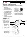
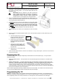
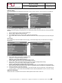
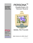
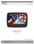
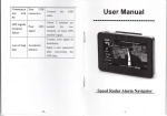
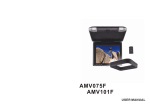
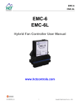
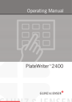
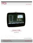
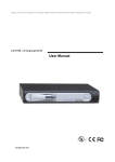
MODEL NUMBER:
Document Number:
PD196-130R4
PDI-P10LCDD
Better Solutions Are Within Reach®
Quick Start Guide
Page 1 of 4
PRODUCT ACCESS ORI ES
(Not Included with TV)
AC Central Pow er Supply
Individual AC Pow er Supply
Support Arm
Support Arm Wall Bracket
Programming Remote Control
PDI-772HE
PDI-750A
PDI-508C-7PIL
PDI-179C, PDI-178C
PD108-420
NOT E TO CABL E TV INSTALLER
This rem in d er is provid ed to ca ll the c ab le T V syste ms
insta lle r’s atte ntion to Artic le 8 2 0-4 0 of th e N atio n al Ele ctric al
Co de. T he c od e p ro vid es g uid elines f or p ro p er g ro u ndin g
an d, in pa rtic ula r, s p ecifies th at th e c a ble gro u nd s h all b e
con n ecte d to t he gro un ding s yste m of th e buildin g, as clos e
to th e point of th e c ab le e ntry as p ractical.
WARNINGS
CAUTION : To re d uce th e risk of electric sh ock d o not
re mov e c ov er (o r b ack ). N o use r s ervic e ab le p arts insid e. Ref er
servic in g t o q u alifie d se rvic e pe rso n ne l.
This sy m bo l is inte n de d to alert t he us er of th e
prese nc e of u ninsu lat ed ‘d a ng ero us v olta g e’
within th e prod uct’s enclos ure th at m ay b e of
sufficie nt m a gnit ud e to c o nstitut e a risk of elect ric
sho ck to p ers o ns.
This s ym bo l is int en d ed t o alert th e us er of th e
prese nc e of im p ort ant o p eratin g a n d m ainte na nc e
(servicing )
instructions
in
th e
lite rat ure
acc om pa nyin g th e a pplia nc e.
WET LOCATION
A pp aratus s hall not b e ex pos e d t o dripp in g or sp las hin g
an d n o o bjects fille d wit h liquids, suc h a s vas es, s hall
be plac e d o n t he a p pa rat us.
RAIN AND MOISTURE
WA RNIN G: To av oid t he ha za rds of fire or e lect rica l
sho ck, D O N OT ex pos e th is televisio n to rain o r
moisture.
OXYGEN ENVIRONMENT
WA RNIN G: D o n ot us e in a ny oxy g en t ent or o xyg e n
cha m be r. S uch us e ma y ca us e a fire haz a rd.
CLEANING AND DISINFECTION
Cle a n th e exte rior of th is televisio n by re m oving d ust
with a lint-free cloth. To avo id d a ma g e t o th e su rfac e of
the televis io n, d o not us e a brasiv e o r ch emic al clea nin g
ag e nts. Do n ot im m ers e this T V. T o av oid d am a ge t o
the su rfac e of t he T V, t est a s ma ll p ortion of th e TV ’s
cab in et wit h a ny n ew disinfect ant to v erify th at th e
disinfect ant do es not d isco lo r or s ofte n th e e nclos ure.
FCC
This eq uipm e nt h as b e en t este d a n d fou n d to c om ply wit h th e
limits fo r a C lass A dig ital d evic e, p urs ua nt to pa rt 1 5 of th e
FCC R ule s. T hes e lim its are de sig n ed to p rov id e re as o na ble
protectio n ag ainst ha rmf ul inte rfe re nc e w h en th e e quip me nt
is o p erate d in a c om me rcial e nviro nm e nt. Th is e quip me nt
ge n erates, use s, a nd c a n radiat e radio fre qu e ncy e n ergy
an d, if not installe d a n d us ed in acc o rd a nce w ith th e
instructio n m an u al, m ay c a us e h armfu l interf ere nce to ra dio
com m unicatio ns. O pe ratio n of th is eq uip me nt in a reside ntial
area is lik ely t o c a use h armfu l inte rfe re nc e in wh ich c ase th e
use r will b e re q uire d to co rrect the inte rfere nce at his ow n
exp e ns e.
MAINTENANCE AND SERVICING
Nev er re m ove th e bac k c ove r of th e T V; this ca n ex pos e y o u
to high v olt ag e an d ot h er h az ards. If the T V d o es n ot
op erate pro pe rly, u np lu g it a nd c all a n a uth orize d se rvic e
cent er or P DI.
DISCONNECTING DEVICE FROM MAINS
Main plug is the disconnecting device. The plug must
remain readily operable.
INSTALLATION INSTRUCTIONS
Th es e se rvicin g inst ru ction s are f o r us e by q u alified s erv ic e
p ers o n n el o nly a n d s h o uld c o nfo rm t o all loc al c o d es. R e a d
a nd fo llow t h e s af ety inst ructio ns b efo re att e m pting th is
inst allation. To re d uc e t he risk of e le ctric s h ock, d o n ot
p erf orm a ny s erv icin g ot h er t h a n c o nt ain ed in t h e o p eratin g
inst ructio ns un le ss y o u are q u alif ie d t o d o s o.
PRODUCT MODIFICATION
Do n ot att em pt to m od ify th is p rod u ct in a ny w ay w ith o ut
writt e n a uth o riz atio n. Un a ut h orize d m o dific at io n co u ld v oid
th e us er’s a ut h orit y to o p erat e t his p ro du ct.
TRADEMA RKS
All brand names and product names in this manual are
trademarks, regis tered trademarks, or trade names of their
respective holder. PDI and Better Solutions Are Within
Reach are regis tered trademarks of PDi Communication
systems, Inc., Springboro, Ohio.
Manufactured under license from Dolby Laboratories.
Dolby and the double-D symbol are trademarks of Dolby
Laboratories.
PDi Communication Sy stems, Inc. 40 Greenwood Lan e Springboro, Ohio 45066 USA PH 1-800-628- 9870 FX 937- 743-5 664
MODEL NUMBER:
Document Number:
PD196-130R4
PDI-P10LCDD
Quick Start Guide
Better Solutions Are Within Reach®
Page 2 of 4
Important Safety Instructions
PLEASE READ AND KEEP THESE INSTRUCTIONS. OBSERVE ALL WARNINGS AND FOLLOW ALL INSTRUCTIONS
CONTAINED IN THESE SAFETY INSTRUCTIONS AND THOSE ON YOUR TELEVISION. RETAIN THESE
INSTRUCTIONS FOR FUTURE USE.
Rea d t hese inst ruc tions .
Ke ep t hese inst ructions .
Hee d all warnings .
Follow all inst ruct ions .
Do not us e t his app arat us near wat er.
Clean only wit h dry c lot h.
Do no block any v entilat ion ope nings . I ns t all
in ac c ordanc e wit h t he ma nuf ac t urer’s
inst ructions .
8. Do not ins t all ne ar any heat s ourc e s uc h as
radiat ors, heat regist ers, st ov e, or ot her
app arat us (inc luding a mplif iers) t hat produc es
heat.
9. Do not def eat t he s af et y purpos e of t he
p olariz e d o r gr o u ndi n g-t y p e plu g. A
p olariz e d pl u g h as t w o bl a de s wit h o n e
wid er t h a n t h e ot h er. A gr o u n din g t y p e
plu g ha s t wo bla d es a n d a t hir d gr o u n din g
pr o ng. Th e wi d e bl a de or t h e t hird pr on g
ar e pr ov i d e d f or y o ur s af et y . If t h e
pr ov i de d plu g d o es n ot f it int o y o ur out l et ,
c o ns ult an elec t ric i a n f or re pl ac e me nt of
t he o bs ol et e out l et .
10. Prot ect t he pow er c ord f rom bein g walk ed on
or pinc he d partic ularly at plugs, c onv enienc e
rec ept acles , and t he point where t hey ex it
from t he apparat us .
1.
2.
3.
4.
5.
6.
7.
Only use att achm ent s/ accessories specified by
t he ma nuf act urer.
12. Use only wit h t he cart ,
st and, t ripod, bracket or
t able specified by t he
man uf act urer, or sold wit h
t he app arat us. W he n a
cart is used, use caut ion
whe n moving t he cart /
app arat us combin ation t o
avoid injury f rom t ip-over.
13. Unplug t his ap parat us
during light ning st orms or when un used f or long
period of time.
14. Ref er all servicing t o qualified service personn el.
Servicing is req uired when t he apparat us has
bee n dam age d in any way, such as pow ersupply cord or plug is da ma ged, liquid has bee n
spilled or object s have f allen int o t he ap parat us,
t he app arat us has bee n exposed t o rain or
moist ure, does not op erat e nor mally, or has bee n
dropp ed.
11.
Installing TV on
Suspension Arm
The PDI- P10LCDD TV is designed
to attach to a wall mounted
suspension
arm
capable
of
supporting a televis ion weighing 7
pounds. The single coaxial cable on
top of the unit is used to supply both
low voltage AC or DC pow er (range
18 to 32 volts) and the RF signal to
the television.
1.
Remove and save the ¾”
Socket Head Cap Screw from
the plastic “H” clip attached to
the TV’s coax cable. Remove
the plastic “H” clip and dis card.
Safety Brake
Pin Hole
DO NOT remov e the
CREAM PLAS TIC CAP
f rom the swiv el
assembly .
Sw ivel Cap
3/4“ Socket Head
Cap Screw
Cloner Cable
Retainer Plate
2.
Remove the tw o nose cover
retainer screws.
Raise the
metal nose cover (not shown)
and
slide
the
television
completely into the arm’s clevis
(slot). The sw iv el retainer plate
should rest inside the nose of
the arm and the plastic swivel
cap beneath.
3.
Align the retainer plate’s
mounting hole over the arm
mounting hole. Thread the ¾”
Socket Head Cap Screw
through the retainer plate and
into the arm’s nose. Tighten.
PDi Communication Sy stems, Inc. 40 Greenwood Lan e Springboro, Ohio 45066 USA PH 1-800-628- 9870 FX 937- 743-5 664
MODEL NUMBER:
Document Number:
PDI-P10LCDD
Better Solutions Are Within Reach®
4.
Quick Start Guide
PD196-130R4
Page 3 of 4
The coax cable in the nose of the arm should be joined w ith the coax cable from
the television. Wrench tighten the connection and cover by sliding the plastic
boot sections into mating position. Lay the Cloner Cable inside the nose
alongside the coax.
IMPORTANT: Finger only tightening of this cable connection w ill
result in reliability problems w eeks or months later. Because the TV
draws its power current through this connection, eventually the
finger-tightened connection w ill loosen, develop resistance and
prompt a service call. Wrench tighten all “F” fitting connections!
5.
Remove the safety brake pin from the parking brake hole, reattach the acorn nut
to the pin, and store the assembly inside the nose of the arm by attaching it to
the coax cable using the attached plastic clip
6.
For PDI-500 series arms remove the Safety Brake Pin from the Safety Brake
Pin Hole, reattach the acorn nut to the pin, and store the assembly inside the
nose of the arm by attaching it to the coax cable using the attached plastic clip.
For PDI-405 series arms remove the Safety Brake Pin from the Safety Brake
Pin Hole and install thru rear mounting holes of the nose cover. Securely
tighten. DO NOT store the pin inside the nose of PDI-405 series arms.
7.
Close the metal nose cover onto the nose. Reinstall the tw o nose cover retainer
bolts.
8.
Some arm models are supplied w ith plastic cosmetic covers. Attach three sets of plastic arm covers (start with long “nose
cover” section):
a.
9.
Assemble supplied spring pins into one of
the arm cover halves. Pins should be
installed into one cover side only.
b.
Position the Arm Cover halves around
the arm’s nose section. Align exposed
pins w ith the open holes in the second
cover half .
c.
Squeeze the two halves together. When
the halves are properly installed there
should only be a thin seam visible where
the halves meet.
d.
Repeat steps a, b, c for the elbow covers
and base covers.
Spring
Pin
Connect the coax cable at the base of the arm to the wall bracket “F” fitting. Wrench tighten. Cycle the arm once or twice to
check for free movement.
Powering the TV
The PDI- P10LCDD is pow ered using low voltage along its coaxial cable from an external power supply . Two types of power
supplies are available.
1.
INDIVIDUAL POWER SUPPLY – This style mounts in the room inside the support arm w all bracket or on the wall near the
support arm.
2.
CENTRAL POWER SUPPLY – A centrally located power supply is usually located in a telephone or electrical closet on the
hospital floor. A dedicated coaxial cable is routed to each bedside TV. When using a central power supply , cable selection is
crucial. Due to long coax cable runs encountered in hospital installations, coax cable employing a solid copper center
conductor and copper shield is required. Cable run lengths MUST NOT exceed 150 feet. Required coaxial cable numbers
include Alpha 9804C (non-plenum), Belden 9248 (non-Plenum), West Penn 806 (non-Plenum), or West Penn 25806 (Plenum),
whic h have been tested with coax-powered televis ions.
Please consult the appropriate power supply installation instructions for further details. The remainder of the instructions assume
you have correctly installed the PDI- P10LCDD w ith appropriate coax power and signal.
Programming the TV
NOTE: A programming remote control is required to perform all setup operations for the television. The programming remote
(Part Number: PD108-420) is NOT packaged w ith the TV and must be ordered separately. The follow ing instructions assume you
have a programming remote, have correctly mounted the TV on the support arm, and connected an RF coax cable signal.
PDi Communication Sy stems, Inc. 40 Greenwood Lan e Springboro, Ohio 45066 USA PH 1-800-628- 9870 FX 937- 743-5 664
MODEL NUMBER:
Document Number:
PDI-P10LCDD
Better Solutions Are Within Reach®
Quick Start Guide
PD196-130R4
Page 4 of 4
Channel Setup
The TV offers three different programmable channel banks or Service Levels to program. Only one Service Level is usable at a
time.
Four different tuning types are available depending upon the healthcare facilities’ signal style.
Selection of the correct signal type is required for the TV to recognize all possible channels and before any channel programming
can begin.
1.
2.
3.
4.
Press the SETUP button to display the SETUP MODE menu.
Press the CH▲ / CH▼ button to select Channels.
In the CHANNEL SETUP menu, press the CH▲ / CH▼ button to select Signal.
Press VOL◄ / VOL► to select Air, Cable STD, Cable IRC or Cable HRC. NOTE: Most hospitals use the Cable STD signal
style.
Auto Program
The TV automatically scans each available channel for activity. Channels that display activ ity are memorized into the selected
Service Level.
1.
2.
3.
4.
5.
6.
7.
From the AUTO PROGRAM menu, press the CH▲ / CH▼ button to select Mode.
Press VOL◄ / VOL► to set the scope of channel scanning.
Analog Only: TV searches for analog channels only.
Digital Only: TV searched for digital channels only .
Analog and Digital: TV searches for both analog and digital channels.
Press the CH▲ / CH▼ button to select the Channel Sequence menu item.
Press VOL◄ / VOL► to set the Channel Sequence in which the channels are dis played after searching.
Interleave A+D: In the order of channel number regardless of the system.
All A then D: Digital channels are dis played after all analog channels .
Press the CH▲ / CH▼ button to select the Servic e Level you w is h to program. The menu displays the current programming
status of each level as either Programmed or Blank. NOTE: A Programmed service level can also be re-programmed if desired.
Press the VOL► button to start auto programming.
A confirmation menu w ill appear before proceeding. Press either the CH▲ to start auto programming. Press CH▼ button to
cancel the operation. The TV will now search all available channels. Press the SETUP button to return to normal TV viewing.
Additional Information
Additional information is available in the user manual. Please request document number: PD196-131.
PDi Communication Sy stems, Inc. 40 Greenwood Lan e Springboro, Ohio 45066 USA PH 1-800-628- 9870 FX 937- 743-5 664