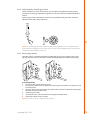
1
FitWeld
Evo 300
Operating manual
EN
Bruksanvisning
DA
Gebrauchsanweisung
DE
Manual de instrucciones
ES
Käyttöohje
FI
Manuel d’utilisation
Manuale d’uso
FR
IT
Gebruiksaanwijzing
NL
Brugsanvisning
NO
Instrukcja obsługi
PL
Manual de utilização
PT
Инструкции по эксплуатации
RU
Bruksanvisning
SV
操作手册
ZH
Operating manual
English
Contents
1.Introduction.................................................................................... 3
1.1General. ............................................... . . . . . . . . . . . . . . . . . . . . . . . . . . . . . . . . . . . . . . . . . . . . . . . . . . . . . . . . . . . . . . . . . . . . . . . . . . . . . . . . . . . . . . . . 3
1.2 About welding.................................. . . . . . . . . . . . . . . . . . . . . . . . . . . . . . . . . . . . . . . . . . . . . . . . . . . . . . . . . . . . . . . . . . . . . . . . . . . . . . . . . . . . . . . . . 3
2.
Using the machine.. ........................................................................ 4
Before use........................................... . . . . . . . . . . . . . . . . . . . . . . . . . . . . . . . . . . . . . . . . . . . . . . . . . . . . . . . . . . . . . . . . . . . . . . . . . . . . . . . . . . . . . . . . 4
Machine introduction. ................... . . . . . . . . . . . . . . . . . . . . . . . . . . . . . . . . . . . . . . . . . . . . . . . . . . . . . . . . . . . . . . . . . . . . . . . . . . . . . . . . . . . . . . . . 4
Distribution network...................... . . . . . . . . . . . . . . . . . . . . . . . . . . . . . . . . . . . . . . . . . . . . . . . . . . . . . . . . . . . . . . . . . . . . . . . . . . . . . . . . . . . . . . . . 4
Connecting cables. ......................... . . . . . . . . . . . . . . . . . . . . . . . . . . . . . . . . . . . . . . . . . . . . . . . . . . . . . . . . . . . . . . . . . . . . . . . . . . . . . . . . . . . . . . . . 4
2.4.1 Connecting to mains. ............... . . . . . . . . . . . . . . . . . . . . . . . . . . . . . . . . . . . . . . . . . . . . . . . . . . . . . . . . . . . . . . . . . . . . . . . . . . . . . . . . . . . . . . . . 5
2.4.2 Earth return cable. .................... . . . . . . . . . . . . . . . . . . . . . . . . . . . . . . . . . . . . . . . . . . . . . . . . . . . . . . . . . . . . . . . . . . . . . . . . . . . . . . . . . . . . . . . . 5
2.4.3 Shielding gas............................. . . . . . . . . . . . . . . . . . . . . . . . . . . . . . . . . . . . . . . . . . . . . . . . . . . . . . . . . . . . . . . . . . . . . . . . . . . . . . . . . . . . . . . . . 5
2.4.4 Welding gun.............................. . . . . . . . . . . . . . . . . . . . . . . . . . . . . . . . . . . . . . . . . . . . . . . . . . . . . . . . . . . . . . . . . . . . . . . . . . . . . . . . . . . . . . . . . 6
2.5 Installing filler wire.......................... . . . . . . . . . . . . . . . . . . . . . . . . . . . . . . . . . . . . . . . . . . . . . . . . . . . . . . . . . . . . . . . . . . . . . . . . . . . . . . . . . . . . . . . . 6
2.5.1 Mounting the wire spool.......... . . . . . . . . . . . . . . . . . . . . . . . . . . . . . . . . . . . . . . . . . . . . . . . . . . . . . . . . . . . . . . . . . . . . . . . . . . . . . . . . . . . . . . . . 6
2.5.2 Feeding in the welding wire. ... . . . . . . . . . . . . . . . . . . . . . . . . . . . . . . . . . . . . . . . . . . . . . . . . . . . . . . . . . . . . . . . . . . . . . . . . . . . . . . . . . . . . . . . . 7
2.5.3 Setting the pressure of the feed rolls. . . . . . . . . . . . . . . . . . . . . . . . . . . . . . . . . . . . . . . . . . . . . . . . . . . . . . . . . . . . . . . . . . . . . . . . . . . . . . 8
2.5.4 Setting the spool brake force... . . . . . . . . . . . . . . . . . . . . . . . . . . . . . . . . . . . . . . . . . . . . . . . . . . . . . . . . . . . . . . . . . . . . . . . . . . . . . . . . . . . . . . . . 8
2.5.5 Wire guide tubes and wire feed rolls.. . . . . . . . . . . . . . . . . . . . . . . . . . . . . . . . . . . . . . . . . . . . . . . . . . . . . . . . . . . . . . . . . . . . . . . . . . . . . . 9
2.5.6 Changing the feed rolls............ . . . . . . . . . . . . . . . . . . . . . . . . . . . . . . . . . . . . . . . . . . . . . . . . . . . . . . . . . . . . . . . . . . . . . . . . . . . . . . . . . . . . . . 10
2.6 Controlling welding functions. .. . . . . . . . . . . . . . . . . . . . . . . . . . . . . . . . . . . . . . . . . . . . . . . . . . . . . . . . . . . . . . . . . . . . . . . . . . . . . . . . . . . . . . . 11
2.6.1 Control panel functions........... . . . . . . . . . . . . . . . . . . . . . . . . . . . . . . . . . . . . . . . . . . . . . . . . . . . . . . . . . . . . . . . . . . . . . . . . . . . . . . . . . . . . . . 11
2.6.2 Controls inside the machine. ... . . . . . . . . . . . . . . . . . . . . . . . . . . . . . . . . . . . . . . . . . . . . . . . . . . . . . . . . . . . . . . . . . . . . . . . . . . . . . . . . . . . . . . 12
2.6.3 Selecting the gun operating mode. . . . . . . . . . . . . . . . . . . . . . . . . . . . . . . . . . . . . . . . . . . . . . . . . . . . . . . . . . . . . . . . . . . . . . . . . . . . . . . 12
2.6.4 Adjusting the shielding gas flow. . . . . . . . . . . . . . . . . . . . . . . . . . . . . . . . . . . . . . . . . . . . . . . . . . . . . . . . . . . . . . . . . . . . . . . . . . . . . . . . . . . 13
2.6.5 Reversing polarity..................... . . . . . . . . . . . . . . . . . . . . . . . . . . . . . . . . . . . . . . . . . . . . . . . . . . . . . . . . . . . . . . . . . . . . . . . . . . . . . . . . . . . . . . 13
2.7Troubleshooting. ............................. . . . . . . . . . . . . . . . . . . . . . . . . . . . . . . . . . . . . . . . . . . . . . . . . . . . . . . . . . . . . . . . . . . . . . . . . . . . . . . . . . . . . . . 14
2.1
2.2
2.3
2.4
EN
3.Maintenance................................................................................. 15
3.1 Daily maintenance. ......................... . . . . . . . . . . . . . . . . . . . . . . . . . . . . . . . . . . . . . . . . . . . . . . . . . . . . . . . . . . . . . . . . . . . . . . . . . . . . . . . . . . . . . . 15
3.2 Maintenance of the wire feed mechanism. . . . . . . . . . . . . . . . . . . . . . . . . . . . . . . . . . . . . . . . . . . . . . . . . . . . . . . . . . . . . . . . . . 15
3.2.1 Cleaning the gun wire liner . . ... . . . . . . . . . . . . . . . . . . . . . . . . . . . . . . . . . . . . . . . . . . . . . . . . . . . . . . . . . . . . . . . . . . . . . . . . . . . . . . . . . . . . . . 15
3.2.2 Replacing the wire liner........... . . . . . . . . . . . . . . . . . . . . . . . . . . . . . . . . . . . . . . . . . . . . . . . . . . . . . . . . . . . . . . . . . . . . . . . . . . . . . . . . . . . . . . 15
3.3Disposal............................................... . . . . . . . . . . . . . . . . . . . . . . . . . . . . . . . . . . . . . . . . . . . . . . . . . . . . . . . . . . . . . . . . . . . . . . . . . . . . . . . . . . . . . . 15
4.
5.
2
Ordering codes............................................................................. 16
Technical data............................................................................... 17
FitWeld Evo 300
1.
Introduction
1.1 General
Congratulations on choosing the FitWeld welding machine. Used correctly Kemppi welding
machines can increase your productivity and provide years of economical service.
This user manual contains important information on the use, maintenance and safety of your
Kemppi product. The technical specifications of the device can be found at the end of the
manual. Please read the operating manual and the safety instructions booklet carefully before
using the equipment for the first time. For your safety and that of your working environment,
pay particular attention to the safety instructions in the manual.
For more information on Kemppi products, contact Kemppi Oy, consult an authorised Kemppi
dealer, or visit the Kemppi Web site at www.kemppi.com.
The specifications presented in this manual are subject to change without prior notice.
NOTE! Items in the manual that require particular attention in order to minimise damage and
personal harm are indicated with this symbol. Read these sections carefully and follow their
instructions.
Disclaimer
While every effort has been made to ensure that the information contained in this guide
is accurate and complete, no liability can be accepted for any errors or omissions. Kemppi
reserves the right to change the specification of the product described at any time without
prior notice. Do not copy, record, reproduce or transmit the contents of this guide without
prior permission from Kemppi.
EN
1.2 About welding
FitWeld Evo 300 is suitable for many MIG/MAG welding applications, but its quick ignition and
high efficiency make it especially fast, safe and economic for tack welding of steel materials. It
can be used for welding with ferrous, stainless steel and aluminium filler materials.
FitWeld Evo 300 is designed for use in demanding environments. It has wire feed cabinet
illumination to facilitate wire adjustment in dark conditions, and its case is made of reinforced
fibre plastic.
Tack welding with the MIG/MAG process
Tack welding is used during the fabrication and fitting process, using spot-like welds to
establish the joints before primary welding.
Using MIG/MAG process for tack welding makes this phase fast and efficient. It is also a safer
compared to traditional MMA tack welding.
© Kemppi Oy / 1515
3
2.
Using the machine
2.1 Before use
The product is packed in cartons designed specifically for them. However, always make sure
before use that the products have not been damaged during transportation.
Check also that you have received the components you ordered and the instruction manuals
needed, as described in the Quick start guide. Product packaging material is recyclable.
Please also read the Safety Instructions included with the package before use.
NOTE! When moving the welding machine, always lift it from the handle, never pull it from the
welding gun or other cables.
Operating environment
This machine is suitable for both indoor and outdoor use. Always make sure that the air flow in
the machine is unrestricted. The recommended operating temperature range is -20 ... +40 °C.
2.2 Machine introduction
EN
4.
7.
1.
2.
5.
6.
3.
1.
2.
3.
4.
5.
6.
7.
ON/OFF
Mains supply cable
Earth return cable
Shielding gas connector
EURO gun connector
Meter displays
Control knobs
2.3 Distribution network
All regular electrical devices without special circuits generate harmonic currents into
distribution network. High rates of harmonic current may cause losses and disturbance to
some equipment.
This equipment complies with IEC 61000-3-12 provided that the short-circuit power Ssc
is greater than or equal to 1.9 MVA at the interface point between the user’s supply and
the public supply network. It is the responsibility of the installer or user of the equipment
to ensure, by consultation with the distribution network operator if necessary, that the
equipment is connected only to a supply with a short-circuit power Ssc greater than or equal
to 1.9 MVA.
2.4 Connecting cables
Before you can start welding with FitWeld Evo 300, you must connect the machine to the
mains power supply, attach the welding gun and the earth return cable and the shielding
gas supply. You must also equip the machine with a filler wire spool suitable for your welding
application.
4
FitWeld Evo 300
For quick help about starting with FitWeld, please refer to the Quick Guide delivered with the
product information package.
2.4.1 Connecting to mains
FitWeld Evo 300 is connected to a 3-phase network using the mains cable supplied with the
machine. The cable is not equipped with a wall plug, so you must install a suitable plug before
you use the machine for the first time.
Check also that the mains cable complies with the local electrical regulations, and replace the
cable if necessary. See ’Technical specifications’.
NOTE! The mains cable or wall plug may be installed or replaced only by an electrical contractor or
installer authorised to perform such operations.
2.4.2 Earth return cable
For creating a closed electric circuit needed in welding, you must connect the earth return
cable to the connector located on the back of the FitWeld. The other end of this cable will be
connected to the workpiece before welding.
NOTE! When attaching the earth return clamp to the work piece, remember to clean the work piece
surface so as to achieve safe and undisturbed operation.
2.4.3 Shielding gas
EN
Secure the snap connector of the shielding gas hose to the gas connector on the back of the
FitWeld machine. Connect the other end of the gas hose to a gas cylinder’s control valve or to
the shielding gas distribution network at your worksite.
Make sure that you are using the correct type of shielding gas for the welding application.
The shielding gas used for steel wires is carbon dioxide or a mixture of argon and carbon
dioxide. The shielding gas used for stainless steel filler wires is a mixture of argon and carbon
dioxide (2%). For aluminium filler wires use pure argon shielding gas.
The thickness of the parent material, joint type and welding power define the required
shielding gas flow rate.
To connect the shielding gas hose to a suitable regulator for MIG/MAG welding
1.
2.
3.
Connect the shielding gas hose to the gas cylinder’s control valve and tighten the
connector (connector is not supplied in the package).
Adjust the shielding gas flow rate with the control valve screw.
Always close the cylinder valve after use.
NOTE! The shielding gas flow rate set from the gas cylinder regulator must exceed the flow rate
measured at the welding gun, if GasGuard function is active. If the flow rate and pressure are the
same, the gas indicator light will shine on the control panel and welding is prevented.
See also instructions and warnings about adjusting the FitWeld's gas flow rate later in this
manual.
© Kemppi Oy / 1515
5
2.4.4 Welding gun
Connect the welding gun cable to the Euro adapter socket located on the front panel and
hand tighten only. Do not over tighten the collar.
The welding gun leads the filler wire, shielding gas and electric current to the weld piece.
When you press the welding gun trigger, shielding gas will flow and filler wire will begin to
feed.
The arc will ignite when the filler wire touches the weld piece. If no ignition, check that the
earth return cable is connected and the clamp has good contact to the work piece.
2.5 Installing filler wire
EN
With FitWeld Evo 300 you can use up to 200 mm diameter wire spools and the following filler
wire types:
• solid wires
• flux-cored wires
• self-shielded flux-cored wires
• stainless steel wires
• aluminium wires.
When choosing the filler wire, remember that the wire must have approximately the same
melting point as the base material to be welded.
NOTE! When changing the filler wire, always check that the feed rolls, their groove shape and size
and the wire liner inside the welding cable are suitable for the wire you are using. Also check that
you are using right polarity for the filler wire.
2.5.1 Mounting the wire spool
NOTE! The liner and the feed rolls are colour-coded. See that you are using feed rolls that match the
colour of the wire liner inside the welding gun cable. See the table of feed rolls and wire liners later
in this chapter.
With FitWeld Evo 300 you can use wire spools with a diameter of 200 mm maximum.
1.
2.
To mount the wire spool:
1. Turn the locking knob of the spool holder so that the locking clips are opened (1).
2. Check the rotating direction of the wire spool and push the spool into its place so that it
rotates in the right direction.
3. Turn the locking knob of the spool holder to close the locking clips (2).
6
FitWeld Evo 300
2.5.2 Feeding in the welding wire
NOTE! Remember to remove the sharp cut tip of the filler wire before loading the wire to the
welding gun, so preventing damage to the liner inside the welding gun cable. This is particularly
important for soft filler wires such as aluminium. It will also improve feed quality and increase the
service life of your gun liner.
For reliable performance only use Kemppi gun liner materials specially developed for use with
Kemppi machines.
For information on recommended liners and wire feed rolls selection, please see the relevant
sections later in this chapter. Be careful not to let the wire unwind from the spool.
NOTE! When feeding the welding wire into the gun, be sure that you are not pointing the gun at
anyone and that there isn’t anything in front of the gun.
EN
To feed the wire from the spool to the welding gun:
1. Open the pressure arm of the GT02 mechanism and lift the top roll clear on its pivot.
2. Draw some loose wire from the spool and carefully push it through the bronze wire
guide at the back of the mechanism. Push the wire over the feed roll groove and through
the front wire guide until it comes out from the Euro connector by about 150mm.
3. Replace the top feed roll over the wire and close the pressure arm.
4. Cut away any deformed wire section and dress the sharp wire tip as described above.
5. Connect the welding gun and tighten the collar.
6. Press the welding gun trigger and allow the filler wire to feed through the gun cable to
the contact tip.
Check once again that the wire is still properly in the grooves of both feed roll pairs. Now the
FitWeld Evo is ready to weld.
© Kemppi Oy / 1515
7
2.5.3 Setting the pressure of the feed rolls
To make filler wire run smoothly into the wire liner and to the welding gun you can adjust the
pressure of the feed rolls of the GT02 WireDrive mechanism.
Turn the orange coloured pressure adjustment knob in a clockwise direction to increase the
pressure applied to the welding filler wire, and anti-clockwise to decrease it.
EN
There is a graduation scale marked on the aluminium arm above the orange adjustment knob.
The more pressure applied, the greater the number of graduation marks visible.
For hard steel and stainless steel filler wires, make sure there is sufficient pressure applied,
so avoiding filler wire slippage in the feed rolls.
NOTE! Too much pressure may flatten the filler wire, damage its coating, cause friction and
excessive wear to drive roll bearings and therefore reduced life.
For aluminium filler wires select the correct feed roll type from the chart supplied and adjust
for the minimum pressure necessary for reliable filler wire drive.
NOTE! Slight slippage is recommended in the case of aluminium filler wires. This ensures that the
soft wire is not deformed and flattened and that the feed rolls skid over the soft wire if gets stuck on
the gun contact tip.
For Aluminium and Stainless Steel filler wires, always use Kemppi DL Chili gun liners. These
liners are especially developed by Kemppi and significantly reduce friction loses, so improving
welding performance.
2.5.4 Setting the spool brake force
To prevent the filler wire from uncoiling on overrun following use at high feed speeds, you can
change the brake force of the welding spool.
Adjust the spool brake force through the hole in the spool locking mechanism with the Allen
key supplied and mounted below the wire drive mechanism.
Increase the force by turning the Allen key clockwise and decrease it by turning it
anticlockwise.
NOTE! Do not over tighten, and reduce the pressure for light filler wire types.
8
FitWeld Evo 300
2.5.5 Wire guide tubes and wire feed rolls
Make sure that you select appropriate wire feed rolls/groove type, welding gun contact tip
and wire liner for the filler wire used.
Kemppi feed rolls and gun liners are colour-coded in order to make identification easy.
Wire guide tubes
ø mm
outlet tube
inlet tube
W003963
W003962
W003881
W003536
ø mm
lower
upper
0.8 – 0.9
W001047
W001048
1.0
W000675
W000676
1.2
W000960
W000961
Ss, Al, (Fe, Mc, Fc)
plastic
Fe, Mc, Fc
metal
Wire feed rolls, plastic
Fe, Ss, (Al, Mc, Fc)
V-groove
Fc, Mc, (Fe)
1.0
W001057
W001058
V-groove, knurled
1.2
W001059
W001060
Al, (Fc, Mc, Ss, Fe)
1.0
W001068
W001067
1.2
W001070
W001069
ø mm
lower
upper
0.8 – 0.9
W006074
W006075
1.0
W006076
W006077
1.2
W004754
W004753
U-groove
EN
Wire feed rolls, metal
Fe, Ss, (Al, Mc, Fc)
V-groove
Fc, Mc, (Fe)
1.0
W006080
W006081
V-groove, knurled
1.2
W006082
W006083
Al, (Fc, Mc, Ss, Fe)
1.0
W006088
W006089
1.2
W006090
W006091
U-groove
© Kemppi Oy / 1515
9
2.5.6 Changing the feed rolls
To change the feed rolls:
1. Pull and release the pressure tension arm via the aluminium head above the orange
plastic adjuster.
2. Lift the upper feed roll on its pivot to the maximum open position.
3. Pull out mounting pin of the upper feed pressure roll and replace the roll with a new one.
4. Open the locking screw of the lower feed roll and replace the roll with a new one.
5. Return the upper pressure feed roll to its down position and replace the locking arm
latch.
6. Adjust the pressure tension as instructed in the earlier section.
1.
2.
EN
3.
4.
5.
When using hard, flux-cored filler wires you should select a knurled feed roll to achieve better
grip.
10
FitWeld Evo 300
2.6 Controlling welding functions
With FitWeld Evo 300 you can easily control welding parameters, change the welding polarity
and gun operating mode.
The control panel provides two adjustment knobs. You can set the desired welding voltage
and wire feed speed before or during welding, so easily tuning the desired arc performance to
the weld.
2.6.1 Control panel functions
FitWeld
10
9
8
7
6 5
4
10
9
8
1
2
3
U
7
6 5
4
ON
1
2
3
W003793
With the left-hand control knob, set the value for filler wire feed speed. The maximum value is
18 meters per minute.
With the right-hand control knob, set the welding voltage. Adjustment range is from 11V to
32V.
The leds on the front panel indicate the following (from top to bottom):
• Machine is turned on
• Machine is overheated
• Error in shielding gas flow
I
EN
A
m
min
U
V
The leds on the right hand side of the upper meter display indicate the showed variable, either
A or m/min. When not welding, the meter displays will show the selected wire feed speed
and voltage. When welding, the meter displays will show the actual current and voltage.
The parameters can be adjusted during welding and the meter displays will show the new
selected value. After welding the meter displays will briefly show an average value of the
actual current and voltage.
© Kemppi Oy / 1515
11
2.6.2 Controls inside the machine
1.
2.
3.
1.
2.
3.
Welding gun operation mode switch.
Shielding gas adjustment screw.
Cable connections for reversing polarity.
2.6.3 Selecting the gun operating mode
EN
With the three position switch (1) you can set the MIG welding gun to two-sequence (2T) or
four-sequence (4T) mode with GasGuard feature on.
If you are using self-shielded flux-cored filler wire (gasless wire), you must select the upmost
switch position. This position provides 2T operation with GasGuard feature disabled, allowing
welding without shielding gas.
To use the welding gun in 2T operating mode:
1.
2.
Press the gun trigger down to start welding.
Release the gun trigger to stop welding.
To use the welding gun in 4T operating mode:
12
1.
2.
3.
Press the gun trigger down to start the flow of the shielding gas.
Release the trigger to start welding.
Press the trigger down again to stop the arc. The shielding gas continues to flow.
4.
Release the switch again to stop the flow of the shielding gas.
FitWeld Evo 300
2.6.4 Adjusting the shielding gas flow
Using a rotameter as shown in the picture, you can adjust the gas flow rate to the gun by
turning the shielding gas adjustment regulation valve screw inside the FitWeld Evo 300 wire
cabinet.
By turning the screw anticlockwise you increase the gas flow to the gun nozzle. Clockwise
adjustment will reduce the gas flow rate.
20
15
10
5
M
T3
M
2
l/min
EN
NOTE! The shielding gas flow rate set from the gas cylinder regulator must exceed the flow rate
measured at the welding gun. If these rates are the same, the gas indication light will shine on the
control panel and welding is prevented.
2.6.5 Reversing polarity
Some filler wires are recommended to be welded with the gun in the negative pole, so the
polarity should be reversed. Check the recommended polarity from the filler wire package.
To reverse polarity:
1. Disconnect the machine from the mains.
2. Pull away the rubber covers to expose the terminal pole connections and allow access to
the Allen screws.
3. Using the Allen key attached to the wire cabinet wall, unscrew the pole connection bolts.
Note the correct order of washers.
4. Interchange the cables.
5. Install the washers in the correct order and tighten the bolts firmly.
6. Replace the rubber covers correctly.
NOTE! The rubber cover must always protect the poles.
© Kemppi Oy / 1515
13
2.7 Troubleshooting
Problem
Cause
The machine stops working and the
shielding gas indicator is lit.
The maximum flow rate at the gas cylinder is set to a lower value than the flow rate
you are trying to set with the FitWeld Evo 300 flow adjustment screw.
• At the gas cylinder’s flow regulator, set the flow rate much higher than what you
are using in welding. The final adjustment of the gas flow rate is accomplished
with the adjustment screw located inside the FitWeld’s wire cabin.
Poor welding result
Several factors affect the welding quality.
• Check that the earth return clamp is properly attached, the point of contact is clean
and that the cable and its connectors are intact.
• Check the voltage and wire speed settings on the control panel are correct for the
given wire size and type.
• Check that the shielding gas flow rate at the gun nozzle is correct.
• Check that the shielding gas is suitable for the filler wire used.
• Check that the wire feed is constant, and adjust if necessary.
• Check that the mains voltage is not irregular, too low or too high.
Overheating indicator lit
The device has overheated.
• Ensure that cooling air has unrestricted flow.
• The machine’s duty cycle has been exceeded. Wait for indicator to turn off.
• Too low or high supply voltage.
The wire does not move or wire feed
entangles
Feed rolls, wire liner or contact tips may be defective
• Check that feed rolls are not too tight or too loose.
• Check that the feed roll groove is not too worn or incorrect size for the filler wire
used.
• Check that the wire liner is the correct size and is not blocked or worn out. Replace
if necessary.
• Check that the contact tip is suitable for the wire used and and is not worn out or
blocked.
EN
Main switch indicator does not switch The machine has no mains voltage
on
• Check the mains fuses
• Check the mains cable and the wall plug
If the machine’s malfunction can not be corrected with these measures, contact KEMPPI
maintenance service.
14
FitWeld Evo 300
3.
Maintenance
When considering and planning routine maintenance, please consider the frequency of
machine use and the working environment.
Correct operation of the machine and regular maintenance will help you avoid unnecessary
downtime and equipment failure.
NOTE! Disconnect the machine from the mains before handling the electrical cables.
3.1 Daily maintenance
• Check the overall condition of the welding gun. Remove welding spatter from the
contact tip and clean the gas nozzle. Replace worn or damaged parts. Only use original
Kemppi spare parts.
• Check the condition and connection of the welding circuit components: welding gun,
earth return cable and clamp, sockets and connectors.
• Check the condition of the feed rolls, needle bearings and shafts. Clean and lubricate
bearings and shafts with a small quantity of light machine oil if necessary. Assemble,
adjust and test function.
3.2 Maintenance of the wire feed mechanism
EN
It is recommended to service the wire feed mechanism every time the you change the wire
spool.
• Check the wear of the feed roll groove and change the feed roll if necessary.
• Clean the welding gun wire guide with compressed air if necessary.
3.2.1 Cleaning the gun wire liner
Pressure of the feed rolls remove metal dust from the filler wire’s surface which then travels
in the wire liner inside the gun cable. If the wire liner is not cleaned, it gradually clogs up,
increasing drag, impairing wire feed performance and weld quality. Ultimately this will will
causes wire feed malfunctions.
To clean the wire liner:
1. Remove the welding gun from the machine.
2. Remove the welding gun’s gas nozzle, contact tip and contact tip adapter.
3. With a pneumatic pistol, blow dry and filtered compressed air through the wire liner.
4. Clean the wire feed mechanism and spool housing with compressed air.
5. Reassemble the welding gun. Firmly tighten the contact tip and contact tip’s adapter.
3.2.2 Replacing the wire liner
If the wire liner is too worn or totally clogged, you must replace it according to the instructions
in welding gun operating manual.
3.3 Disposal
Do not dispose of electrical equipment with normal waste!
In observance of European Directive 2002/96/EC on waste electrical and electronic
equipment, and its implementation in accordance with national law, electrical equipment
that has reached the end of its life must be collected separately and taken to an appropriate
environmentally responsible recycling facility.
The owner of the equipment is obliged to deliver a decommissioned unit to a regional
collection centre, per the instructions of local authorities or a Kemppi representative. By
applying this European Directive you will improve the environment and human health.
© Kemppi Oy / 1515
15
4.
Ordering codes
FitWeld Evo 300
FitWeld Evo 300 + FE32 3,5M
P2103
FitWeld Evo 300 + FE32 5M
P2104
FE32 3,5M
6603203
FE32 5M
6603204
FE35 3,5M
6603503
FE35 5M
6603504
MMT 32, 3 m
6253213MMT
MMT 32, 4.5 m
6253214MMT
Earth return cable, 35 mm², 5 m
6184311
Shield gas hose, 6 m
W000566
EN
16
FitWeld Evo 300
5.
Technical data
Connection voltage
Rated power at max. current
Supply current
Output 40 °C
Connection cable
Fuse (delayed)
Open circuit voltage
Power factor at max. current
Efficiency at max. current
3 ~, 50/60 Hz
10.8 kVA
30 % ED I1max
220 – 230 V: 29 A
30 % ED I1max
380 – 440 V: 17 A
30 % ED I1eff
220 – 230 V: 16 A
30 % ED I1eff
380 – 440 V: 9 A
30 % ED
300 A / 29.0 V
40 % ED
250 A / 26.5 V
60 % ED
210 A / 24.5 V
100 % ED
170 A / 22.5 V
H07RN-F
4G1.5 (5 m)
220 – 230 V
16 A
380 – 440 V
10 A
220 V AC
42 V DC
440 V AC
86 V DC
220 – 230 V
0.93
380 – 440 V
0.94
220 – 230 V
83 %
380 – 440 V
84 %
Welding voltage range
Wire spool (max. ø)
Wire feed mechanism
Wire feed speed
Filler wires
220 V -10% ... 440 V +10 %
EN
11 – 32 V
200 mm
2-roll feed
0 – 18 m/min
Fe solid, Fe cored, 0.8 – 1.2 mm
Ss
Al
LxWxH
External dimensions
Weight
EMC class
Minimum short circuit power Ssc of supply network*
Degree of protection
Operating temperature range
Storage temperature range
Standards: IEC/EN 60974-1, IEC/EN 60974-5, IEC/EN 60974-10
1.0 – 1.2 mm
457 x 226 x 339 mm
15.4 kg
A
1.9 MVA
IP23S
-20 °C ... +40 °C
-40 °C ... +60 °C
* See paragraph 2.3.
© Kemppi Oy / 1515
17
KEMPPI OY
Kempinkatu 1
PL 13
FIN-15801 LAHTI
FINLAND
Tel +358 3 899 11
Telefax +358 3 899 428
[email protected]
www.kemppi.com
Kotimaan myynti:
Tel +358 3 899 11
Telefax +358 3 734 8398
[email protected]
KEMPPI SVERIGE AB
Box 717
S-194 27 UPPLANDS VÄSBY
SVERIGE
Tel +46 8 590 783 00
Telefax +46 8 590 823 94
[email protected]
KEMPPI NORGE A/S
Postboks 2151, Postterminalen
N-3103 TØNSBERG
NORGE
Tel +47 33 346000
Telefax +47 33 346010
[email protected]
KEMPPI DANMARK A/S
Literbuen 11
DK-2740 SKOVLUNDE
DANMARK
Tel +45 4494 1677
Telefax +45 4494 1536
[email protected]
KEMPPI BENELUX B.V.
NL-4801 EA BREDA
NEDERLAND
Tel +31 765717750
Telefax +31 765716345
[email protected]
www.kemppi.com
KEMPPI FRANCE S.A.S.
65 Avenue de la Couronne des Prés
78681 EPONE CEDEX
FRANCE
Tel +33 1 30 90 04 40
Telefax +33 1 30 90 04 45
[email protected]
KEMPPI GMBH
Perchstetten 10
D-35428 LANGGÖNS
DEUTSCHLAND
Tel +49 6 403 7792 0
Telefax +49 6 403 779 79 74
[email protected]
KEMPPI SPÓŁKA Z O.O.
Ul. Borzymowska 32
03-565 WARSZAWA
POLAND
Tel +48 22 7816162
Telefax +48 22 7816505
[email protected]
KEMPPI AUSTRALIA PTY LTD
13 Cullen Place
P.O. Box 5256, Greystanes NSW 2145
SMITHFIELD NSW 2164
AUSTRALIA
Tel. +61 2 9605 9500
Telefax +61 2 9605 5999
[email protected]
OOO KEMPPI
Polkovaya str. 1, Building 6
127018 MOSCOW
RUSSIA
Tel +7 495 240 84 03
Telefax +7 495 240 84 07
[email protected]
ООО КЕМППИ
ул. Полковая 1, строение 6
127018 Москва
Tel +7 495 240 84 03
Telefax +7 495 240 84 07
[email protected]
KEMPPI, TRADING (BEIJING) COMPANY LTD
Unit 105, 1/F, Building #1,
No. 26 Xihuan South Rd.,
Beijing Economic-Technological Development
Area (BDA),
100176 BEIJING
CHINA
Tel +86-10-6787 6064
+86-10-6787 1282
Telefax +86-10-6787 5259
[email protected]
肯倍贸易(北京)有限公司
中国北京经济技术开发区
西环南路26号
1号楼1层105室(100176)
电话: +86-10-6787 6064/1282
传真: +86-10-6787 5259
[email protected]
KEMPPI INDIA PVT LTD
LAKSHMI TOWERS
New No. 2/770,
First Main Road,
Kazura Garden,
Neelankarai,
CHENNAI - 600 041
TAMIL NADU
Tel +91-44-4567 1200
Telefax +91-44-4567 1234
[email protected]
KEMPPI WELDING SOLUTIONS SDN BHD
No 12A, Jalan TP5A,
Taman Perindustrian UEP,
47600 Subang Jaya,
SELANGOR, MALAYSIA
Tel +60 3 80207035
Telefax +60 3 80207835
[email protected]
1903530
1515
KEMPPI (UK) LTD
Martti Kemppi Building
Fraser Road
Priory Business Park
BEDFORD, MK44 3WH
UNITED KINGDOM
Tel +44 (0)845 6444201
Telefax +44 (0)845 6444202
[email protected]