1
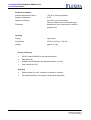
User Manual
PM3AC10-1x
Bidirectional 2.3 kW DC/AC Inverter Module
Article-No.: BNH-PM3AC10-1x
Edition/Review date: 27.03.2015
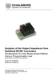
User Manual DC/AC-Module PM3AC10-1x
Preface
Preface
The present Technical Documentation is to inform of the correct operation and
handling of the DC/AC module module PM3AC10 (DC/AC module). The modules
serve to convert a direct voltage (e.g. DC link of the converter) into an alternating
voltage of 230V / 50Hz.
The operating manual is to be preserved.
It is prohibited to copy or duplicate texts, plans, and tables or to make them
accessible to any third parties without our express consent.
We draw your attention to the fact that the Technical Documentation shall not be part
of an existing earlier agreement or promise or part of a legal relationship.
All and any obligations result from the purchase contract that also solely contains the
warranty determination. The contractual provisions shall not be affected by the
Technical Documentation.
The documentations of the suppliers used shall apply along with the present
documentation of the manufacturer.
In addition to the operating manual, all universally valid legal and other obligatory
regulations concerning the prevention of accidents and the environmental protection
are to be complied with and to be applied.
2
Flexiva automation & Robotik GmbH
Weißbacher Straße 3
D – 09439 Amtsberg
User Manual DC/AC-Module PM3AC10-1x
Table of Contents
Table of Contents
1 Introduction ................................................................................................................ 6
2 Identification ............................................................................................................... 7
2.1 Product Trademark and Type Designation .......................................................... 7
2.2 Product Version / Version of Software / Editing State.......................................... 7
3 Product Description ................................................................................................... 8
3.1 General Information / Utilization as Directed ....................................................... 8
3.2 Technical Information and Data........................................................................... 9
3.3 Power Connectors ............................................................................................. 11
3.4 Signal Connectors ............................................................................................. 12
3.5 Basic Structure and Method of Functioning of the DC/AC Module .................... 14
3.6 Safety Information ............................................................................................. 14
3.6.1 Safety Measures for the Installation...................................................... 15
3.6.2 Remaining Dangers and Risks.............................................................. 15
3.6.3 Qualification of the Operating Staff ....................................................... 15
4 Preparation of the Product for the Use................................................................... 16
4.1 Transport of the Module .................................................................................... 16
4.2 Packaging of the Module ................................................................................... 16
4.3 Storing of the Module ........................................................................................ 16
4.4 Commissioning of the Module ........................................................................... 16
4.4.1 Connection of the DC Link (DC link side).............................................. 16
4.4.2 Connection of the Output (AC side) ...................................................... 16
4.4.3 Connection of the Auxiliary Supply ....................................................... 17
4.4.4 Connection of the Communication ........................................................ 17
4.4.5 Putting the Module into Operation......................................................... 17
5 Operation .................................................................................................................. 18
5.1 Method of Functioning ....................................................................................... 18
5.1.1 Modes of Operation .............................................................................. 18
5.1.2 Monitoring Functions / Shutdowns on Faults ........................................ 19
5.2 Parameterization ............................................................................................... 23
5.2.1 Parameters and Measured Values of the Output Side (AC side) .......... 23
5.2.2 Parameters and Measured Values for the DC Link Side....................... 25
5.2.3 Information ............................................................................................ 28
5.2.4 Commands............................................................................................ 29
5.2.5 Oscilloscope.......................................................................................... 30
5.3 Voltage Regulation of the DC Link..................................................................... 33
5.4 Parallel Connection ........................................................................................... 36
5.5 Multiphase Operation ........................................................................................ 37
5.6 Typical Cases of Application / Parameterization Examples ............................... 37
5.6.1 DC Link Voltage Modes ........................................................................ 38
5.6.2 Parameter DC Link Voltage Regulator .................................................. 38
5.6.3 Single Module at the Mains................................................................... 39
5.6.4 Single Module at the Network with DC/DC Module at the DC Link ....... 39
5.6.5 Multiple Modules at the Network ........................................................... 41
5.6.6 Single Module in Island Operation ........................................................ 41
Flexiva automation & Robotik GmbH
Weißbacher Straße 3
D – 09439 Amtsberg
3
User Manual DC/AC-Module PM3AC10-1x
Table of Contents
5.7
5.6.7 Parallel Operation in Island Operation .................................................. 42
5.6.8 Multiphase System in Island Operation................................................. 44
Error Handling ................................................................................................... 45
6 Programming / Parameterization ............................................................................ 46
6.1 Preliminary Remarks ......................................................................................... 46
6.2 The ASCII Protocol used ................................................................................... 47
6.2.1 Read / write without checksum ............................................................. 47
6.2.2 Read / write with checksum .................................................................. 47
6.2.3 ASCII-long / ASCII-short ....................................................................... 49
6.2.4 ASCII-short with checksum ................................................................... 50
6.2.5 Switching between the protocols........................................................... 51
6.2.6 Concrete example ................................................................................. 52
6.2.7 Error messages during the communication........................................... 54
6.3 Communication by Means of a Terminal Software ............................................ 55
6.4 Communication by Means of ModuleConfigSuite .............................................. 55
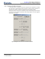
7 The Parameterizing Software "ModuleConfigSuite" ............................................. 56
7.1 Preliminary Remarks ......................................................................................... 56
7.2 Installation ......................................................................................................... 56
7.3 Deinstallation ..................................................................................................... 56
7.4 Software description .......................................................................................... 57
7.4.1 Overview ............................................................................................... 57
7.4.2 Single-Mode / Multi-Mode ..................................................................... 57
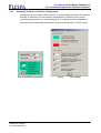
7.4.3 Groupings by Means of Colours / Backgrounds.................................... 59
7.4.4 Meaning of the Error Codes .................................................................. 60
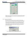
7.4.5 Selection and Assignment of the Interfaces .......................................... 60
7.4.6 Connecting / Disconnecting .................................................................. 61
7.4.7 Storing / Loading of Parameter Sets ..................................................... 62
7.4.8 Reading-Out / Parameterization............................................................ 62
7.4.9 Data Visualization / Recording .............................................................. 63
7.4.10 Selecting of the Mode of Operation....................................................... 65
8 Maintenance service and repairs by the customer service .................................. 66
9 Appendix ................................................................................................................... 67
4
Flexiva automation & Robotik GmbH
Weißbacher Straße 3
D – 09439 Amtsberg
User Manual DC/AC-Module PM3AC10-1x
Table of Figures
Table of Figures
Fig. 1:
Fig. 2:
Fig. 3:
Fig. 4:
Fig. 5:
Fig. 6:
Fig. 7:
Fig. 8:
Fig. 9:
Fig. 10:
Fig. 11:
Fig. 12:
Fig. 13 :
Fig. 14:
Fig. 15:
Fig. 16:
Fig. 17:
Fig. 18:
Fig. 19:
Fig. 20:
Fig. 21:
Fig. 22:
Power connectors............................................................................................................11
Signal connectors............................................................................................................12
Labeling of master and slaves in the module carrier.......................................................13
Structure of the DC/AC module.......................................................................................14
Block diagram of the DC link voltage control in mains operation ....................................33
Block diagram of the DC link voltage control in island operation ....................................34
Block diagram of falling characteristic of DC link voltage control ....................................35
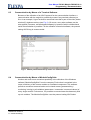
Module parameterization by means of a terminal software.............................................55
Basic structure of the software ........................................................................................57
Single-mode / module 3 ..................................................................................................58
Multi-mode.......................................................................................................................58
Example for groupings ....................................................................................................59
Color legend ....................................................................................................................59
Example of error codes ...................................................................................................60
Meaning of the error codes .............................................................................................60
Assignment of the interface.............................................................................................61
Information in case of the cutting-off of the connection...................................................61
Dialogue for the loading of parameter files......................................................................62
Buttons for the reading-out / parameterization in the single-mode..................................63
Dialogue field storing / visualizing ...................................................................................63
Recorded ASCII data ......................................................................................................63
Dialogue for the selection of the mode of operation........................................................65
Table of Tables
Tab. 1:
Tab. 2:
Tab. 3:
Tab. 4:
Tab. 5:
Tab. 6:
Tab. 7:
Tab. 8:
Tab. 9:
Tab. 10:
Tab. 11:
Tab. 12:
Tab. 13:
Tab. 14:
Tab. 15:
Tab. 16:
Tab. 17:
Tab. 18:
Tab. 19:
Tab. 20:
Tab. 21:
Tab. 22:
Tab. 23:
Tab. 24:
Pin assignment SV3 ........................................................................................................13
mod_opmode ..................................................................................................................19
Options in island operation..............................................................................................19
Options in mains operation..............................................................................................19
Error codes......................................................................................................................21
Modes of operation of oscilloscope .................................................................................31
Status values of oscilloscope ..........................................................................................32
Settings RS232 ...............................................................................................................46
Command sequences without checksum in general .......................................................47
Command sequences with checksum in general ............................................................47
Complete table of the command codes...........................................................................48
Module answer for the reading of a parameter / value...................................................49
Module answer for the writing of a parameter / value ....................................................49
Module answer during reading of a parameter / value ...................................................50
Module answer during writing of a parameter / value.....................................................50
Protocol changeover .......................................................................................................51
Reading ASCII-long.........................................................................................................52
Writing ASCII-long...........................................................................................................52
Reading ASCII-short .......................................................................................................52
Writing ASCII-short..........................................................................................................52
Reading ASCII-short with checksum...............................................................................53
Writing ASCII-short with checksum .................................................................................53
Example for computing the checksum in C .....................................................................53
Error messages ...............................................................................................................54
Flexiva automation & Robotik GmbH
Weißbacher Straße 3
D – 09439 Amtsberg
5
User Manual DC/AC-Module PM3AC10-1x
Introduction
1 Introduction
In order to guarantee the safety of the operator and to avoid possible damages at the
module, you have to ensure by all means that the present user's manual has been
read completely before starting to use the module and/or the plant connected with it.
The present user's manual is to help you to get to know the DC/AC module better and
to enable you to use it according to the intended working possibilities.
Prior to the commissioning, the operating staff has to familiarize itself with all subunits and their functions. Particular attention is to be paid to the paragraph safety.
The present user's manual contains important information on the correct and
economical application of the DC/AC module. The compliance with these instructions
contributes to the fact that dangers are avoided, costs owing to repairs and
breakdown times are reduced, and the service life of the module is prolonged.
A symbol is provided at the text margin in the chapters if required that refers to the
function of the respective text section and is of importance with regard to the
operation or the maintenance and/or indicates important descriptions or notes:
Danger
All sections in the manual containing information on possible dangers are marked
with the marginal symbol.
The non-observance can lead to serious injuries! The instructions are to be strictly
complied with.
Attention
All sections with this symbol provide instructions how to avoid damages at the unit.
Advice
Sections with this symbol give important details for an efficient work.
The work steps that are described in logical order at the side of this symbol inform
the operator of the most ergonomic proceeding of the operation.
6
Flexiva automation & Robotik GmbH
Weißbacher Straße 3
D – 09439 Amtsberg
User Manual DC/AC-Module PM3AC10-1x
Identification
2
Identification
2.1
Product Trademark and Type Designation
ZEMIS® PM3AC10
2.2
Product Version / Version of Software / Editing State
Product Version:
PM3AC10-1x
Firmware:
2.13
State:
2015
Flexiva automation & Robotik GmbH
Weißbacher Straße 3
D – 09439 Amtsberg
7
User Manual DC/AC-Module PM3AC10-1x
Product Description
3
Product Description
3.1
General Information / Utilization as Directed
The DC/AC module serves to generate an alternating voltage from a direct voltage
(e.g. DC link voltage of 375V). It is intended to be used in connection with the DC/DC
converter modules of the type PM3Kxxx. Both, island operation and mains operation,
are possible with the DC/AC module i.e. it is possible to operate a single electric
consumer as well as to feed into the power supply system.
Attention
The DC/AC module does not offer any galvanic isolation of the DC link and the
output! In case of the interconnection with other modules without galvanic isolation,
this can lead to the damaging of the DC/AC module.
Terms and abbreviations
DC link:
Prefix: _zk
Output:
Prefix: _a
8
DC link (DC side)
This is the designation for the side of the module by means of
which the coupling with DC/CC modules or the link of any other
DC component can be carried out.
Output side (AC side, component side)
On that side of the module, the mains as well as the electric
consumers can be connected (depends on the selected operation
mode).
Mains
operation:
(on-grid)
In the mains operation, the DC/AC module is connected to the
electric network and works as a current source. In this case, both
feeding into the mains, as well as power drain from the mains is
possible.
Island
operation:
(off-grid)
In the island operation, electric consumers can be directly
connected to the DC/AC module. It works as a voltage source.
Flexiva automation & Robotik GmbH
Weißbacher Straße 3
D – 09439 Amtsberg
User Manual DC/AC-Module PM3AC10-1x
Product Description
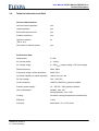
3.2
Technical Information and Data
General characteristics
Grid-connected operation:
yes
Island operation:
yes
Bi-directional power flow:
yes
Parallel connection:
yes
Galvanic isolation:
(ZK vs. AC)
no
Generation of reactive power:
yes
Performance data
Rated power:
2.3 kW
AC current range:
0…10ARMS
AC voltage range:
0…250VRMS (output voltage < DC link voltage)
Rated frequency:
50Hz, 60Hz
Frequency range in island operation:
40Hz-70Hz
Overload capability in island operation:
16ARMS for max. 30s
DC link voltage:
100…395V DC
Control interface:
USART (CMOS 5V); galvanic isolated
Auxiliary power supply:
12…30V DC, 10W; galvanic isolated
Own consumption:
standby: max. 5W
during operation: max. 10W
Cooling:
forced air cooling (temperature-controlled fan)
Efficiency:
> 90%
Accuracy:
better than ± 3 % of full scale
Flexiva automation & Robotik GmbH
Weißbacher Straße 3
D – 09439 Amtsberg
9
User Manual DC/AC-Module PM3AC10-1x
Product Description
Ambient conditions
Ambient temperature range :
Degree of protection:
Maximum humidity:
Pollutants:
-20..50°C (during operation)
IP 00
up to 90% (non-condensing)
The environment must not contain larger
quantities of dust, in particular no metal or
graphite dust.
Housing
Design:
open frame
Dimensions:
270 mm x 85 mm x 105 mm
Weight:
approx. 2.9 kg
Scope of delivery
DC/AC module PM3AC10 (pre-parameterized)
Data disk (CD)
Software for visualization and parameterization (on CD)
User manual (on CD)
Optional
10
Device system for max. 4 modules (variants on request)
Pre-parameterization according to the planned application
Flexiva automation & Robotik GmbH
Weißbacher Straße 3
D – 09439 Amtsberg
User Manual DC/AC-Module PM3AC10-1x
Product Description
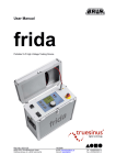
3.3
Power Connectors
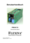
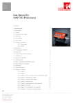
Fig. 1:
Power connectors
X1: DC link connection (DC side, DC link)
Plug with clamp max. 2.5mm²
X2: Connection for auxiliary supply
Plug with clamp max. 1.5mm²
12…30V DC
X3: Output connection (AC side, component side)
Plug with clamp max. 2.5mm²
N, L, PE
Flexiva automation & Robotik GmbH
Weißbacher Straße 3
D – 09439 Amtsberg
11
User Manual DC/AC-Module PM3AC10-1x
Product Description
3.4
Signal Connectors
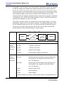
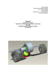
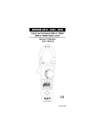
Fig. 2:
Signal connectors
SV1: Communication interface
The communication with the module is executed by means of an optically isolated
serial interface: To trigger the optocouplers, a supply voltage of 5V (approx. 30mA) is
to be provided. To permit to address several modules in a simple way, the signals
RXD and TXD can be switched-in by means of the SELECT signal. When SELECT is
low, TXD becomes a high-resistance value and RXD does not receive any signals.
When several modules are used, the RXD and TXD lines can be connected in parallel
this way and the currently addressed module can be selected by means of SELECT.
Data rate: 115200 bps,
Format: 8 bit + 1 stop bit
The signals OC_OK and OC_EN are provided for an additional safety feature:
OC_OK gets low, when the DC link voltage has exceeded the upper limit value.
Consequently, a module can inform all the others when this case has occurred by
AND-combining all OC - OK signals and supplying them to OC - EN. This way, it is
possible to prevent major damages when the voltage-measuring amplifier of the DC
link of a module breaks down.
12
Flexiva automation & Robotik GmbH
Weißbacher Straße 3
D – 09439 Amtsberg
User Manual DC/AC-Module PM3AC10-1x
Product Description
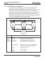
1
2
3
4
5
Abbreviation
GND
VCC
OC_OK
NC
NC
6
SELECT
7
8
9
10
OC_EN
RXD
NC
TXD
Pin
Explanation
ground
+5 V
H: no overvoltage of the DC link
not used
not used
H: serial interface activated
L: serial interface deactivated
H: module enabled
input of data
not used
output of data
Tab. 1:
Pin assignment SV3
SV2, SV3, SV4, SV5, TST: Service interfaces
The service interfaces are not needed for the operation and are not to be used.
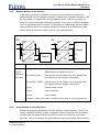
JP1, JP2, JP4: SYNC-IN / SYNC_OUT: Synchronizing inputs/outputs
These connections serve for the synchronization of several modules in the island
operation in case of parallel connection or multiphase operation. If the
synchronization has been successful, the signal at SYNC_OUT is in phase to the
signal at SYNC_IN. A parameterized phase displacement has only effects on the
power output, not on the signal at SYNC_OUT.
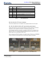
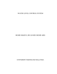
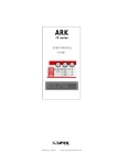
When using several DC/AC modules in a module carrier of Flexiva (e.g. WG5K020)
master and slaves are already factory connected and labeled accordingly.
Fig. 3:
Flexiva automation & Robotik GmbH
Weißbacher Straße 3
D – 09439 Amtsberg
Labeling of master and slaves in the module carrier
13
User Manual DC/AC-Module PM3AC10-1x
Product Description
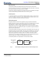
3.5
Basic Structure and Method of Functioning of the DC/AC Module
K1
+
R1
ZK
3,3µF L
K2
2mF
EMI
6,6µF
N
-
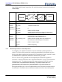
Fig. 4:
Structure of the DC/AC module
The negative pole of the DC link is gallvanically connected with the N-connection of
the AC side. The L-connection of the AC side can be maximally the DC link voltage
+UZK and minimally the DC link voltage -UZK.
In the switched-off condition, the contacts K1 and K2 are open. During the switchingon, K2 is closed first and charges the possibly empty DC link by means of the resistor
R1. These are two PTC resistors of the type EPCOS B59754D0120A70, each with a
value of 150Ohm in cold condition, that are switched in parallel. If the DC link cannot
be charged because of an error (short circuit, too high capacity), these resistors get
high-resistance resistors and limit the current to an undangerous value.
After the successful charging of the DC link, the contact K1 is closed and the power
stage is switched-in.
3.6
Safety Information
The DC/AC modules were developed according to recognized rules of technology
and submitted to a safety test before the delivery.
In case of wrong operations or unauthorized use, there are still dangers for persons
and the DC/AC module.
All persons who erect, operate, or maintain the system must:
14
1.
read and exactly follow the present operating manual,
2.
be trained and instructed for their job.
Flexiva automation & Robotik GmbH
Weißbacher Straße 3
D – 09439 Amtsberg
User Manual DC/AC-Module PM3AC10-1x
Product Description
Test voltage between DC link side and communication interface: 6kVp
Test voltage between DC link side and auxiliary supply: 6kVp
3.6.1
Safety Measures for the Installation
In order to guarantee a troublefree operation and to maintain the service life of the
electronic components, any accumulation of heat, especially at the fronts of the
module (fan and opposite side) is to be avoided. The place of installation is to be
selected so that the module is sufficiently ventilated during the operation.
Attention
The heat sinks are connected with potentials i.e. it is prohibited to touch them!
3.6.2
Remaining Dangers and Risks
The described product is in keeping with the latest technological development and
meets the recognized safety provisions. Nevertheless, dangers and risks may arise.
The remaining dangers and risks occurring in connection with the operation of the
system result from:
the utilization of electric / electronic components /sources, acceptors, memories) of
third-party suppliers,
the electricity itself.
For all components built-in, the provisions and safety instructions with regard to the
operation and the place of erection and/or installation applying to each of them are to
be observed and complied with.
3.6.3
Qualification of the Operating Staff
Only such persons are authorized to commission and connect the module who have
an electro-technical special training and who are able to execute the required line
connections expertly.
Basic knowledge of the work on PCs and with the current WINDOWS operating
system is required to use the software supplied along with the modules. Details about
this are contained in the enclosed extensive program description.
Flexiva automation & Robotik GmbH
Weißbacher Straße 3
D – 09439 Amtsberg
15
User Manual DC/AC-Module PM3AC10-1x
Preparation of the Product for the Use
4
Preparation of the Product for the Use
4.1
Transport of the Module
For the transport of the module, attention has to be to the fact that it is not exposed to
any vibrations, heavy shocks as well as jolts and impacts since sensitive components
might be damaged by that.
4.2
Packaging of the Module
Basically, packaging is to be used for the transport and/or shipment of the module
that meets the requirements of the destination and the system and is environmentally
acceptable.
Since the module itself has a degree of protection IP00, a transport packing is to be
selected that prevents the penetrating of water, dirt, and dust. The inserting of
conventional desiccating means in the packaging is recommended.
4.3
Storing of the Module
Durable storing: closed rooms, dry, room temperature
4.4
Commissioning of the Module
Prior to the commissioning, the following conditions are to be assured and to be
checked:
The expert installation and rating of all necessary electrical connection lines as
well as the correct connection of all components to the module.
The knowledge of the information and instructions given in the present user's
manual.
4.4.1
Connection of the DC Link (DC link side)
The cross section of the wires has to be selected according to the expected
current at least 1.5mm² are recommended.
Take into account the polarity.
4.4.2
Connection of the Output (AC side)
The cross section of the wires has to be selected according to the expected
current at least 1.5mm² are recommended.
16
Flexiva automation & Robotik GmbH
Weißbacher Straße 3
D – 09439 Amtsberg
User Manual DC/AC-Module PM3AC10-1x
Preparation of the Product for the Use
4.4.3
Connection of the Auxiliary Supply
12…30V DC, 1.5mm²
Observe the polarity!
4.4.4
Connection of the Communication
5V DC operating voltage required.
CMOS level level converter to RS232 level required.
OC_EN has to be set to +5V for operation.
4.4.5
Putting the Module into Operation
1. Read the present documentation
2. Connect the auxiliary supply
3. Parameterize
4. Switch it on
Flexiva automation & Robotik GmbH
Weißbacher Straße 3
D – 09439 Amtsberg
17
User Manual DC/AC-Module PM3AC10-1x
Operation
5
Operation
5.1
Method of Functioning
The DC/AC module is suited for the supply of directly connected electrical loads
(island operation). In this case, the output voltage (AC side) is kept at a constant
level. The operation at the mains (mains operation) is possible, too. Here, the output
current (AC side) is kept at a constant level. In this mode of operation, a bidirectional
working is possible i.e. power can also be drawn from the mains and supplied to the
DC link. For the changeover between the two, the parameter for the mode of
operation of the module (mod_opmode) has to be changed.
The output variables current and voltage are sinusoidal. For the control of the DC link
voltage, a PIT1 regulator is available that is realized by means of software. Its output
is connected with the desired values for the output variable and, thus, offers various
possibilities for the voltage control of the DC link.
5.1.1
Modes of Operation
The DC/AC module offers various modes of operation. In principle, you can
distinguish between 2 groups of modes of operation: modes of operation in island
operation and modes of operation in mains operation. The switchover between island
and mains operation is done by means of bit 1 of the parameter mod_opmode. The
following tables give a survey over the possible modes of operation in the two groups
of modes of operation and the corresponding bit combinations of the parameter
mod_opmode.
If bit 1 of mod_opmode is 0, it works in the island operation. If bit 0 is 0, a PI regulator
is used to control the output voltage, if bit 0 is 1, a PI regulator with resonant
integrator is used. In both modes of operation, there exists a regulator for the DC link
voltage limiting the same downwards.
If bit 1 is 1, the DC/AC module can be operated at the mains. Bit 0 has no function yet
here and should be 0. The DC/AC module works in this case as current source. There
are two DC link voltage regulators available. One for a (selectable) lower voltage limit,
the other for a (selectable) upper voltage limit.
Assistance during the fixing of the right mode of operation is offered by the
corresponding dialogue in the software „ModuleConfigSuite“ (See 7.4.10).
18
Flexiva automation & Robotik GmbH
Weißbacher Straße 3
D – 09439 Amtsberg
User Manual DC/AC-Module PM3AC10-1x
Operation
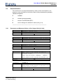
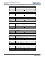
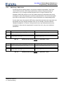
Parameter: mod_opmode
Bit
Dec
Meaning in island operation
0
1
Type of the output voltage regulator
not used
1
2
Island operation / Mains operation
Island operation / Mains operation
2
4
not used
not used
3
8
DC link voltage mode
DC link voltage mode
4
16
not used
Reactive current mode
5
32
Synchronisation
not used
6
64
Mehrphasenbetrieb / Parallelbetrieb
not used
7
128
not used
not used
Tab. 2:
Meaning in mains operation
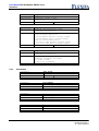
mod_opmode
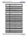
Parameter: mod_opmode
Bit
Dec
Hex
Meaning
0 x x 0 x 0 0 0
0
0x00
PI regulator
0 x x 0 x 0 0 1
1
0x01
Resonant PI regulator
0 x x 0 0 0 0 x
0
0x00
Normal DC link voltage range 350..400V
0 x x 0 1 0 0 x
8
0x08
Full DC link voltage range 0..400V
0 0 1 0 x 0 0 x
32
0x20
Parallel mode
0 1 1 0 x 0 0 x
96
0x60
Multi-phase mode
7 6 5 4 3 2 1 0
Tab. 3:
Options in island operation
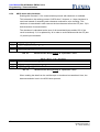
Parameter: mod_opmode
Bit
Dec
Hex
Meaning
0 0 0 x x 0 1 0
2
0x02
Mains operation
0 0 0 x 0 0 1 x
0
0x00
Normal DC link voltage range 350..400V
0 0 0 x 1 0 1 x
8
0x08
Full DC link voltage range 0..400V
0 0 0 0 x 0 1 x
2
0x02
Reactive power via phase angle setting
0 0 0 1 x 0 1 x
18
0x12
Reactive power via reactive current setting
7 6 5 4 3 2 1 0
Tab. 4:
5.1.2
Options in mains operation
Monitoring Functions / Shutdowns on Faults
The module is equipped with numerous monitoring functions that are explained in the
following. If there is a fault shutdown executed, the corresponding bits (see table
below) are set in the variable mod_state. Before the module can be restarted, the
faults occurred have to be acknoweldged by setting the variable err_quit to 1.
Flexiva automation & Robotik GmbH
Weißbacher Straße 3
D – 09439 Amtsberg
19
User Manual DC/AC-Module PM3AC10-1x
Operation
Overcurrent at the output (island operation, mains operation)
"Overcurrent at the output"
Is indicated when the hardware overcurrent shutdown was activated.
Overvoltage at the DC link (island operation, mains operation)
"U_ZK too high“
If the DC link voltage exceeds 400V, there is a fault shutdown carried out.
In the full range DC link voltage mode, there is an additional shutdown carried out if
the DC link voltage exceeds the value 1,5*zk_usollvh.
Overtemperature (island operation, mains operation)
"Overtemperature“
For the overtemperature shutdown, the temperature of the heat sink element is
monitored. At a temperature of more than 90 °C at the heat sink element, the
shutdown is carried out with an error message.
Undervoltage at the DC link (island operation, mains operation)
"U_ZK too low“
In the normal range DC link voltage mode, there is a shutdown carried out because of
DC link undervoltage at 351V.
In the full range DC link voltage mode, it is distinguished between mains operation
and island operation. In both cases, i.e. in mains operation as well as island
operation, a shutdown is carried out if the DC link voltage zk_uist is smaller than 95%
of the bottom desired value zk_usollv.
In the mains operation, a fault shutdown is carried out if zk_uist<a_ueff*1.4 is, i.e. if
the peak voltage at the output (AC side) is more than 99% of the DC link voltage.
In the island operation, a fault shutdown is carried out if the DC link voltage is smaller
than the peak value of the desired value of the output voltage (AC side).
Overload (island operation)
"Overload“
Is more power demanded on the AC side than is available via the DC link, the DC link
voltage regulator reduces the output voltage. If as a result the output voltage is
smaller than the desired value for more than 10s, a fault shutdown is carried out.
If the output current exceeds a value of 10.5A for more than 30s, a fault shutdown is
carried out.
20
Flexiva automation & Robotik GmbH
Weißbacher Straße 3
D – 09439 Amtsberg
User Manual DC/AC-Module PM3AC10-1x
Operation
Frequency deviation (island operation, mains operation)
"Frequency deviation“
In the mains operation, the frequency of the DC/AC module is constantly adjusted
according to the mains frequency by means of PLL. If a deviation of the
parameterized desired frequency from the mains frequency is determined that is more
than 0.5Hz, a fault shutdown is carried out.
In the island operation, the frequency is also monitored, namely in the parallel
operation and in the multiphase operation. Here, a fault shutdown is carried out when
the frequency differs more than 4,5Hz from the set value.
Synchronization error (island operation, mains operation)
"Synchronization error“
When the synchronization failed in the mains operation or in the parallel operation /
multiphase operation (synchronized island operation), a fault shutdown is carried out.
In the island operation, this fault is also indicated in the following cases:
There is no valid synchronization signal available.
(Frequency not between 37..74Hz).
In the parallel operation, before switching-on, the slave module compares its
own phase with the phase relation of the voltage of the master module. If
these do not correspond, a fault shutdown is carried out.
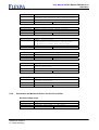
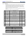
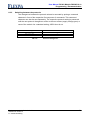
Parameter: mod_state
Bit
Dec
Hex
Meaning in mains operation
Meaning in island operation
0 0 0 0 0 0 0 0
0
0x00
no error
no error
0 0 0 0 0 0 0 1
1
0x01
Overcurrent at the output
Overcurrent at the output
0 0 0 0 0 0 1 0
2
0x02
U_ZK too high
U_ZK too high
0 0 0 0 0 1 0 0
4
0x04
Overtemperature
Overtemperature
7 6 5 4 3 2 1 0
0 0 0 0 1 0 0 0
8
0x08
U_ZK too low
U_ZK too low
0 0 0 1 0 0 0 0
16
0x10
Frequency deviation
Frequency deviation / Overload
0 0 1 0 0 0 0 0
32
0x20
Synchronization error
Synchronization error
0 1 0 0 0 0 0 0
64
0x40
Over-/under- voltage at the output
Output not voltage-free
1 0 0 0 0 0 0 0
128
0x80
Hardware error
Hardware error
Tab. 5:
Error codes
Monitoring of the output voltage (island operation, mains operation)
Island operation: "Output not voltage-free“
Mains operation: "Overvoltage/undervoltage at the output“
Flexiva automation & Robotik GmbH
Weißbacher Straße 3
D – 09439 Amtsberg
21
User Manual DC/AC-Module PM3AC10-1x
Operation
Prior to the switching-on, the existence of a voltage at the output is checked. If there
is no voltage available in the mains operation or if there is already a voltage in the
island operation, a fault shutdown is carried out.
In the mains operation, the mains voltage is monitored, too. If it differs by +/- 15%
from the desired value, a fault shutdown is carried out.
Hardware error (island operation, mains operation)
"Hardware error“
A hardware error either occurs when there has a problem in the power supply of the
module occurred or when the overvoltage shutdown of the DC link of another module
was triggert and the signal OC_EN is low at the communication interface.
22
Flexiva automation & Robotik GmbH
Weißbacher Straße 3
D – 09439 Amtsberg
User Manual DC/AC-Module PM3AC10-1x
Operation
5.2
Parameterization
The module can only be parameterized by means of the serial interface. It is,
however, more convenient to do this by means of the parameterizing software
"ModuleConfigSuite“.
R
readable
W
writable (parameterizable)
E
stored in the EEPROM (EEP)
B
can be changed in switched-on state (mod_on=1)
---------------------------------------------------------------------------------------5.2.1
Parameters and Measured Values of the Output Side (AC side)
parameter
description
explanation
command
a_fsoll
frequency, desired value
scaling: 40Hz…70Hz -> 4000…7000
RW
wf
parameter
description
explanation
command
a_fsoll_f
frequency, desired initial value in eeprom
scaling: 40Hz…70Hz -> 4000…7000
RW E
wg
parameter
description
explanation
command
a_fist
frequency, actual value
scaling: 40Hz…70Hz -> 4000…7000
R
wh
parameter
description
a_phase
phase angle of the current in mains op.
(limited to ±40°)
power into the mains: +capac. -induct.
power from the mains: +induct. -capac.
phase angle of the voltage in multiph. op.
scaling: -180°…180° -> -1800…1800
RW
wp
explanation
command
parameter
description
explanation
command
a_phase_f
phase angle of the current in mains op.
phase angle of the voltage in multiph. op
initial value in eeprom
scaling: -180°…180° -> -1800…1800
RW E
wq
Flexiva automation & Robotik GmbH
Weißbacher Straße 3
D – 09439 Amtsberg
23
User Manual DC/AC-Module PM3AC10-1x
Operation
parameter
description
explanation
command
parameter
description
explanation
command
parameter
description
explanation
command
a_isoll_f
current, desired value, mains operation,
initial value in eeprom
scaling: -10A…10A -> -1000…1000
RW E
wj
a_iblind_soll
reactive current, desired value, mains op.,
+ capacitive reactive current
- inductive reactive current
scaling: -10A…10A -> -1000…1000
RW B
wk
explanation
command
a_iblind_soll_f
reactive current, desired value, mains op.,
initial value in eeprom
scaling: -10A…10A -> -1000…1000
RW E
wl
parameter
description
explanation
command
a_usoll
voltage, desired value
scaling: 0…260V -> 0…2600
RW B
wu
parameter
description
a_usoll_f
voltage, desired value,
initial value in eeprom
scaling: 0…260V -> 0…2600
RW E
wv
parameter
description
explanation
command
parameter
description
explanation
command
parameter
description
explanation
command
24
a_isoll
current, desired value, mains operation
+ power into the grid
- power from the grid
scaling: -10A…10A -> -1000…1000
RW B
wi
a_kri
internal resistance, desired value
(parallel operation only)
scaling: 0…26.1 Ohm -> 0…255
RW E
wz
a_ueff
r.m.s. value of the output voltage
(between module and its internal relay)
scaling: 0…400V -> 0…4000
R
vu
Flexiva automation & Robotik GmbH
Weißbacher Straße 3
D – 09439 Amtsberg
User Manual DC/AC-Module PM3AC10-1x
Operation
explanation
command
n_ueff
r.m.s. value of the mains voltage
(between the internal relay and the mains)
scaling: 0…400V -> 0…4000
R
vw
parameter
description
explanation
command
a_ieff
r.m.s. value of the output current
scaling: 0…20A -> 0…2000
R
vi
parameter
description
explanation
command
a_p
power, actual value
+ power is delivered to the AC side
- power is taken from the AC side
scaling: -8000W…8000W -> -8000…8000
R
vp
parameter
description
explanation
command
a_udc
voltage, DC component
scaling: -1.524V…1.572V -> -1524…1527
R
vd
parameter
description
a_iampl
current, actual amplitude value
(mains operation)
scaling: -10Aeff…10Aeff -> -1000…1000
R
vj
parameter
description
explanation
command
parameter
description
explanation
command
5.2.2
a_uampl
voltage, actual amplitude value
(island operation)
scaling: 0…260V -> 0…2600
R
vv
Parameters and Measured Values for the DC Link Side
Normal voltage range
parameter
description
explanation
command
zk_usoll
voltage, lower regulator, desired value
scaling: 350V…400V -> 3500…4000
RW B
zu
Flexiva automation & Robotik GmbH
Weißbacher Straße 3
D – 09439 Amtsberg
25
User Manual DC/AC-Module PM3AC10-1x
Operation
explanation
command
zk_usoll_f
voltage, lower regulator,
desired initial value in eeprom
scaling: 350V…400V -> 3500…4000
RW E
zv
parameter
description
explanation
command
zk_usollh
voltage, upper regulator, desired value
scaling: 350V…400V -> 3500…4000
RW B
zs
parameter
description
zk_usollh_f
voltage, upper regulator,
desired initial value in eeprom
scaling: 350V…400V -> 3500…4000
RW E
zt
parameter
description
explanation
command
parameter
description
explanation
command
zk_uist
voltage, actual value
resolution
0V…350V:
0.4 V
resolution 350V…400V: app. 0.07V
scaling: 0V…400V -> 0…4000
R
za
Full voltage range
parameter
description
explanation
command
zk_usollv
voltage, lower regulator,desired value
scaling: 0V…400V -> 0…4000
RW B
zq
parameter
description
explanation
command
zk_usollv_f
voltage, lower regulator,
desired initial value in eeprom
scaling: 0V…400V -> 0…4000
RW E
zr
parameter
description
explanation
command
zk_usollvh
voltage, upper regulator,desired value
scaling: 0V…400V -> 0…4000
RW B
zo
parameter
description
zk_usollvh_f
voltage, upper regulator,
desired initial value in eeprom
scaling: 0V…400V -> 0…4000
RW E
zp
explanation
command
26
Flexiva automation & Robotik GmbH
Weißbacher Straße 3
D – 09439 Amtsberg
User Manual DC/AC-Module PM3AC10-1x
Operation
parameter
description
explanation
command
zk_uistv
voltage, actual value
resolution: 0…400V: 0.4V
scaling: 0V…400V -> 0…4000
R
zb
Normal / Full voltage range
parameter
description
explanation
command
parameter
description
explanation
command
parameter
description
explanation
command
parameter
description
explanation
command
parameter
description
explanation
command
parameter
description
explanation
command
zk_umax_g
voltage, upper limit
scaling: 0V…400V -> 0…4000
not used
RW E
zm
zk_umin_g
voltage, lower limit
scaling: 0V…400V -> 0…4000
not used
RW E
zn
zk_ki
regulator, I-component
parameter range: 0…1023
transfer function: G=VI/p
VI: 0…602s-1
VI=zk_ki*4825Hz/8192
RW E
yi
zk_kp
regulator, P-component
parameter range: 0…1024
gain: 0…4
RW E
yp
zk_kt
regulator, time constant
parameter range: 0…1024
transfer function: G=1(1+pT)
T: 212ms…0.21ms
T=1024/(zk_kt*4825Hz)
RW E
yt
zk_uf
voltage window for the gain increase
parameter range: 0…150
voltage range:
0…±10V (normal voltage range),
0…±15V (full voltage range)
RW E
yf
Flexiva automation & Robotik GmbH
Weißbacher Straße 3
D – 09439 Amtsberg
27
User Manual DC/AC-Module PM3AC10-1x
Operation
parameter
description
explanation
command
parameter
description
explanation
command
parameter
description
explanation
command
5.2.3
28
zk_kv
gain increase outside the voltage window
parameter range: 0…255
gain: 0…16
RW E
yv
zk_fkkp
falling characteristic, gain
„internal resistance“
parameter range: 0…255
gain in mains operation:
0…13V/10Aeff (normal voltage range)
0…20V/10Aeff (full voltage range)
gain in island operation:
0…13.5V/2.3kW (normal voltage range)
0…20.5V/2.3kW (full voltage range)
RW E
yk
zk_fkkt
falling characteristic, filter time const.
„internal resistance“
parameter range: 0…1024
transfer funktion: G=1(1+pT)
T: 212ms…0.21ms
T=1024/(zk_kt*4825Hz)
RW E
yz
Information
parameter
description
explanation
command
mod_state
module, state
see Tab. 5
R
Is
parameter
description
explanation
command
mod_opmode
module, operating mode
see Tab. 3
RW E
im
parameter
description
explanation
command
module, type
module type: AC2
R
it
parameter
description
explanation
command
module, firmware
software version of the firmware
R
if
Flexiva automation & Robotik GmbH
Weißbacher Straße 3
D – 09439 Amtsberg
User Manual DC/AC-Module PM3AC10-1x
Operation
5.2.4
parameter
description
explanation
command
module, serial number
serial number of the manufacturer
R
in
parameter
description
explanation
command
module, date of manufacture
date of manufacture
R
id
parameter
description
explanation
command
t_kk
temperature, heat sink
scaling: –112…160°C -> -1120…1600
R
tk
Commands
parameter
description
explanation
command
mod_on
module on / off
1: on
0: off
RW B
ce
parameter
description
explanation
command
err_quit
acknowledge an error
1: acknowledging the error
RW B
cq
parameter
description
explanation
command
com_mode
communication mode
0: ASCII short
1: ASCII long
R B
cc
Flexiva automation & Robotik GmbH
Weißbacher Straße 3
D – 09439 Amtsberg
29
User Manual DC/AC-Module PM3AC10-1x
Operation
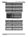
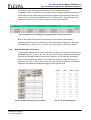
5.2.5
Oscilloscope
For the setting of the regulator parameters and for the observing in the operation, an
oscilloscope functionality is integrated into the software. By means of it, output
voltage, DC link voltage and output current can be recorded. 13 channels with 512
values each with a scope of values of 16bit are recorded. The possible scanning
frequency is in the range from 9.654 kHz and 37.9 Hz.
The channel where triggering is done can be selected independently of the recorded
channel.
The values are not scaled. i.e. they are internal operands.
Ch
Description
zk_uist
1
zk_uist_v
2
i_aistb
3
n_uist
4
a_uist
5
l1_iist
Current inductor 1
6
l2_iist
Current inductor 2
7
usoll
Desired voltage value
(in island operation only)
8
isoll
Desired current value
9
il1_soll_glob
Desired current value of inductor 1
(identical to inductor 2)
10
sin_ampl
Amplitude of the desired value:
voltage in island operation
current in mains operation
11
a_udc
DC voltage component at the output
12
l1_soll_glob
Desired voltage value for
the Modulator
parameter
description
explanation
command
osz_ch
channel
parameter range: 0…12
RW B
ok
parameter
description
explanation
osz_ft
frequency devider
clock: 9.654kHz/osz_ft
0 corresponds to 9.654kHz
RW B
of
command
30
DC link voltage
normal voltage range
DC link voltage
full voltage range
Output current, actual value,
calculated from l1_iist and l2_iist
Mains voltage,
actual value
Output voltage,
actual value
0
Scaled
range
5280
6040
0
+4000
-2970
+2970
-1952
+1952
-2014
2014
-2120
1976
-2120
1952
-2014
2014
-2120
2120
-2120
1976
-790
790
0
906
-1952
1952
-2014
2014
Real
range
350V
400V
0V
+400V
-20A
+20A
-400V
+400V
-400V
+400V
-19.9A
+18.5A
-19.9A
+18.5A
-400V
400V
-19.9A
+19.9A
-19.9A
+18.5A
-10A
10A
0V
260V
-1.5V
1.5V
-400V
400V
Flexiva automation & Robotik GmbH
Weißbacher Straße 3
D – 09439 Amtsberg
User Manual DC/AC-Module PM3AC10-1x
Operation
parameter
description
explanation
command
osz_tr
trigger value
trigger value for all channels
RW B
ot
parameter
description
explanation
command
osz_tch
trigger channel
parameter range: 0…12
RW B
oc
parameter
description
explanation
command
osz_m
storage mode
see Tab. 6
RW B
om
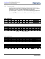
Parameter: osz_m
Bit
Dec
Hex
Meaning
x x x x x x x 0
0
0x00
trigger at: value > trigger value
x x x x x x x 1
1
0x01
trigger at: value < trigger value
x x x 0 0 x x x
0
0x00
trigger position: 0 %
7 6 5 4 3 2 1 0
x x x 0 1 x x x
8
0x08
trigger position: 25%
x x x 1 0 x x x
16
0x10
trigger position: 50%
x x x 1 1 x x x
24
0x18
trigger position: 75%
Tab. 6:
Modes of operation of oscilloscope
parameter
description
explanation
command
osz_on
oscilloscope on / off
start/stop; status
RW B
oe
parameter
description
explanation
read data, only the channel osz_ch
reads the 512 values (ASCII,
separated by 0x0D 0x0A)
R
or
command
parameter
description
explanation
command
Flexiva automation & Robotik GmbH
Weißbacher Straße 3
D – 09439 Amtsberg
read data, all channels
reads all the values of all
channels (ASCII, separated by
blank, end of line: 0x0D)
R
os
31
User Manual DC/AC-Module PM3AC10-1x
Operation
Parameter: osz_on
Bit
Dec
Hex
Meaning
0 0 0 0 0 0 0 0
0
0x00
not running
x x x x x x x 1
1
0x01
runs, waits for trigger
x x x x x x 1 x
2
0x02
runs, triggert
x x x x x 1 x x
4
0x04
runs, forerun before trigger
7 6 5 4 3 2 1 0
Tab. 7:
32
Status values of oscilloscope
Flexiva automation & Robotik GmbH
Weißbacher Straße 3
D – 09439 Amtsberg
User Manual DC/AC-Module PM3AC10-1x
Operation
5.3
Voltage Regulation of the DC Link
Measuring Ranges
For the voltage measurement and regulation of the DC link, there are two voltagemeasuring ranges available. These can be switched over by means of bit 3 of the
parameter mod-opmode.
If bit 3 is 0, a voltage range of 350V to 400V with a resolution of approx. 0.07V is
available. This range recommends itself in connection with other components of the
modular transformer system of Flexiva.
If bit 3 is 1, the full voltage range from 0V to 400V is available but only with a
resolution of 0.4V. This range recommends itself if the DC link voltage can become
smaller than 355V. In this case, attention has to be paid to the fact that the DC link
voltage has to be bigger than 1.4 when it is multiplied by the root-mean-square value
of the output voltage.
Voltage Regulator
zk_kt
zk_uist
Filter
PT1
zk_ki
zk_kp
zk_usoll
zk_uf
PI
zk_kv
a_isoll
zk_ki
zk_usollh
-
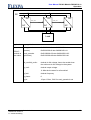
Fig. 5:
sin_ampl
zk_ki
PI
Block diagram of the DC link voltage control in mains operation
Flexiva automation & Robotik GmbH
Weißbacher Straße 3
D – 09439 Amtsberg
33
User Manual DC/AC-Module PM3AC10-1x
Operation
zk_kt
zk_uist
Filter
PT1
zk_ki
zk_kp
zk_usoll
zk_uf
PI
zk_kv
a_usoll
Fig. 6:
sin_ampl
Block diagram of the DC link voltage control in island operation
The voltage control of the DC link is digitally realized and designed as represented in
the figures above. It works as follows: The measured value of the DC link voltage gets
first into a comb filter that suppresses the ripple factor that is caused by the
fluctuating power. This ripple factor has the double value of the output frequency.
Then, the comparison with the desired value and the PIT1 regulator follows. To
suppress additionnally a possibly existing ripple factor of the DC link voltage that
would lead to a distortion of the sine-wave form of the output voltage it is possible to
define a voltage window (zk_uf). Within this voltage window, the actual-desired value
difference is not additionnally amplified. Outside this window, the difference is
additionnally amplified with the factor zk_kv. Thanks to that, it is reached that a ripple
factor on the DC link voltage acts on the output amplitude only with a low gain in the
stationary condition what leads to low distortions. In case of big deviations, e.g. step
changes in load, the range of the high gain is reached what leads to a quick
smoothing.
In mains operation, two DC link voltage regulators are provided, an upper and a lower
one. The upper regulator works when the DC link voltage exceeds its desired value
and effects that power is supplied into the mains and/or the power taken from the
mains is reduced. The lower regulator works when the DC link voltage remains under
its desired value and effects that power is taken from the mains or the power supplied
into the mains is reduced.
In the island operation, only one DC link voltage regulator is used. It reduces the
output voltage if its desired values is remained under.
34
Flexiva automation & Robotik GmbH
Weißbacher Straße 3
D – 09439 Amtsberg
User Manual DC/AC-Module PM3AC10-1x
Operation
Mains Operation
In the mains operation, the voltage control of the DC link can be used to feed
excessive power into the mains or to draw lacking power from the mains. In this case,
the current is limited to the maximum value of 10Aeff.
If the DC link voltage is between the two desired values of the regulators, the output
current is determined by the desired value of the current (a_isoll).
Island Operation
In the island operation, only one DC link voltage regulator is active. In case of a too
low DC link voltage, it reduces the output voltage. But if this condition lasts for more
than 10s, a shutdown is carried out because of overload.
Falling Characteristic
During the utilization of the DC link regulation in case of modules connected in
parallel, tolerances during the measurement of the DC link voltage lead to an uneven
load distribution. In order to make the load distribution more even, a falling
characteristic of the DC link voltage regulation can be set that simulates an internal
resistance. By means of an additional low pass, it is possible to suppress undesired
higher-frequency disturbances.
In the mains operation, the output current (in form of the desired value sin_ampl, see
Fig. above) is used as control variable. The more power is shifted from a source into
the DC link the bigger gets the output current leading to the consequence that the
desired value of the DC link voltage is raised. If a module connected in parallel
maintains the DC link voltage at a slightly lower value this means that the current is
reduced owing to that. Thereby, the load distribution gets evener.
In the island operation, the output power is used as control variable.
Mains operation
zk_fkkt
to the regulator
sin_ampl
Island operation
PT1
zk_fkkp
a_p
zk_usoll
Fig. 7:
Block diagram of falling characteristic of DC link voltage control
Flexiva automation & Robotik GmbH
Weißbacher Straße 3
D – 09439 Amtsberg
35
User Manual DC/AC-Module PM3AC10-1x
Operation
5.4
Parallel Connection
Mains Operation
In the mains operation, it is possible to connect in parallel as many modules as you
like. You only have to pay attention to the fact that N is connected with N and L is
connected with L at the output. A connection of L with N can result in a damage of the
modules.
You can specify any desired values of current you like to every module.
If the DC link voltage regulation is to be used, the same falling characteristic is to be
parameterized at all modules connected in parallel for an even load distribution. Here,
it is recommended to set a DC link voltage step of approx. 5V between no-load and
full-load.
Island Operation
In the island operation, the modules connected in parallel have to be synchronized.
For this purpose, the SYNC-OUT output of the master module has to be connected to
the SYNC-IN input of the next module. The SYNC-OUT output of the latter with the
SYNC-IN input of the following etc.
The master module is parameterized for normal island operation (bit 5=0). The slave
modules are parameterized with bit 5=1 and bit 6=0 in mod_opmode.
The desired values of the output voltage of all modules connected in parallel have to
be parameterized identically. The phase relation has also to be parameterized at all
modules to the same value (recommended all to 0). For the compensation of
circulating currents owing to tolerances, a fine adjustment can be carried out by
means of these two parameters after the commissioning. A modification of the
desired values of the voltage leads to the flowing of reactive current, a phase
displacement mainly to active current.
Furthermore, it is possible to define an internal resistance (parameter a_kri) that leads
to an even load distribution. This should be identical at all modules connected in
parallel. If the normal PI regulator is selected (bit 0=0 in mod_opmode), this is not
absolutely required since this regulator has a steady-state deviation in case of a sinewave desired value. If the resonant PI regulator is selected (bit 0=1 in mod_opmode),
it is a must to parameterize an internal resistance.
First of all, the master module has to be switched on, then the slave modules that
check the phase relation before their switching-in. A check of the voltage is not
carried out since, when only the master module is in operation at the beginning, this
module is possibly overloaded and the voltage generated by it (the master) could be
too low.
36
Flexiva automation & Robotik GmbH
Weißbacher Straße 3
D – 09439 Amtsberg
User Manual DC/AC-Module PM3AC10-1x
Operation
5.5
Multiphase Operation
Mains Operation
In the mains operation, the modules can be distributed to several phases as you like.
It is important that all N-connections of the modules are connected with the Nconnection of the mains. An operation at mains without accessible star point is not
possible.
If the DC link voltage regulation is to be used, the falling characteristic is to be
parameterized at all phases for an even load distribution. Here, it is recommended to
set a DC link voltage step of approx. 5V between no-load and full-load.
Island Operation
For the setting-up of a multiphase island network, the modules have to be
synchronized. For this purpose, the SYNC-OUT output of the master module has to
be connected to the SYNC-IN input of the next module. The SYNC-OUT output of the
latter with the SYNC-IN input of the following etc. Of course, it is possible to connect
in parallel modules to all these modules to increase the power. These modules have
to be synchronized, too. After the successful synchronization, the output SYNC_OUT
is always in phase to SYNC_IN.
The master module is parameterized for normal island operation (bit 5=0). The slave
modules are parameterized with bit 5=1 and bit 6=1 in mod_opmode as such.
The desired values of the output voltage have to be parameterized identically. The
phase relation has to be parameterized at all modules to the desired phase
displacement, e.g. 0°,+120° and –120° in case of a three-phase network.
5.6
Typical Cases of Application / Parameterization Examples
To be able to operate the DC/AC module in a certain arrangement, some parameters
have to be placed correctly. In the following example configurations, useful
instructions are given for the correct parameterization of a DC/AC module in
connection with a DC/DC module of the type PM3Kxxx of Flexiva.
Attention
During the initial charging of the DC link it must be unloaded, i.e. there have to be
no additional electrical capacities and / or electrical loads connected to the DC link.
Flexiva automation & Robotik GmbH
Weißbacher Straße 3
D – 09439 Amtsberg
37
User Manual DC/AC-Module PM3AC10-1x
Operation
5.6.1
DC Link Voltage Modes
In principle, 2 voltage ranges are available with regard to the DC link, the normal DC
link voltage range and the full DC link voltage range. In case of the utilization of the
DC/AC module with DC/DC modules of the type PM3Kxxx of Flexiva, the utilization of
the normal DC link voltage range is recommended for reasons of compatibility, i.e. the
DC link range of 350…400V.
For applications requiring another DC link voltage (formed, for example, under the
utilization of batteries), the full DC link voltage range, namely the DC link range of
0…400V, should be used. For reasons of efficiency, a DC link voltage of more than
100V is to be recommended in operation. It has to be taken into account that the peak
value of the output voltage has to be always smaller than the DC link voltage.
Consequently, a maximum output voltage of 70 Veff is possible at a DC link voltage of
100V.
5.6.2
Parameter DC Link Voltage Regulator
The following parameters for the DC link voltage regulator lead in the most cases to
an acceptable behaviour. An optimization can be appropriate in certain cases. The
oscilloscope function will help to do this.
Command
yi
38
Parameter
zk_ki
65
Recommended values
yp
zk_kp
350
yt
zk_kt
1000
yf
zk_uf
50
yv
zk_kv
128
yk
zk_fkkp
0
only a single module
100 in parallel operation
yz
zk_fkkt
120 in mains operation
6
in island operation
without effect if zk_fkkp=0
Flexiva automation & Robotik GmbH
Weißbacher Straße 3
D – 09439 Amtsberg
User Manual DC/AC-Module PM3AC10-1x
Operation
5.6.3
Single Module at the Mains
In example a), the operation of a DC/AC module at the mains is shown. The DC link
voltage is supplied from outside. Depending on the voltage range, bit 3 is to be set
from mod_opmode.
If the DC link voltage is between zk_usoll and zk_usollh, no DC link voltage regulator
is active and the current can be specified as you like by means of the parameter
a_isoll (+ into the mains). Of course, the DC link side source and/or sink is loaded
by that what can lead to a change of the DC link voltage. If the DC link voltage
reaches the upper and/or lower desired value, the output current is automatically
increased and/or reduced by the module.
Depending on bit 4 in mod_opmode, a desired reactive current as phase
displacement (a_phase) or as desired value of the reactive current (a_iblind_soll) can
be specified.
a)
ZK
DC
Mains
AC
application
any application
parameter
mod_opmode:
DC/ACmodule at
the mains
0b00000010=2 / 0b00001010=10
0b00010010=18 / 0b00011010=26
zk_usoll/zk_usollv:
desired lower dc link voltage, has to be smaller than
the minimum dc link voltage in the system
zk_usollh/zk_usollvh: desired upper dc link voltage, has to be bigger than
the maximum dc link voltage in the system
a_isoll: (+/-)
desired output current
a_fsoll:
mains frequency
a_usoll:
mains voltage
a_phase/a_iblind_soll phase / reactive current, dep. on mod_opmode bit 4
5.6.4
Single Module at the Network with DC/DC Module at the DC Link
In connection with a DC/DC converter module of the type PM3Kxxx of Flexiva, the
DC/AC module can serve as a network front end for a bidirectional DC source/sink. In
connection with an accu, it is possible to set up, for example, a memory unit this way.
Flexiva automation & Robotik GmbH
Weißbacher Straße 3
D – 09439 Amtsberg
39
User Manual DC/AC-Module PM3AC10-1x
Operation
In example b), such a memory unit is represented. If the DC/DC module can maintain
the DC link voltage at its desired value (this lies between the two desired values of
the DC/AC module), the desired value of the current can be set as you like by means
of the parameter a_isoll. If the DC/DC converter module gets to a current limit or if the
end-of-charge voltage of the memory is reached, the DC module can no longer
maintain the DC link voltage at its desired value and the DC link voltage runs upwards
or downwards. Here, the DC link voltage regulation of the AC module intervenes and
maintains the voltage at zk_usoll or zk_usollh.
The DC/DC converter module only monitors the end-of-charge voltage, i.e. the endof-discharge voltage has to be monitored externally. The regulator parameters of the
DC link voltage regulator are to be set, e.g. with the aid of the oscilloscope function,
so that only a low ripple factor gets from the DC link to the VS side of the DC/DC
module and thus to the electrical storage ( reduce gains).
VS
b)
ZK
DC
Accu
ZK
DC
DC
AC
Mains
application
electrical storage
parameter
mod_opmode:
0
DC/DCmodule at
the accu
vs_imax:
+ desired current limit
vs_imin:
- desired current limit
zk_usoll:
desired dc link voltage
vs_usoll:
end-of-charge voltage of the storage
parameter
mod_opmode:
0b00000010=2 / 0b00010010=18
DC/ACmodule at
the mains
zk_usoll:
desired lower dc link voltage, has to be smaller than
the desired dc link voltage of the DC/DC module
(min. 5V difference)
zk_usollh:
desired upper dc link voltage, has to be bigger than
the desired dc link voltage of the DC/DC module
(min. 5V difference)
a_isoll:
desired output current
a_fsoll:
mains frequency
a_usoll:
mains voltage
a_phase/a_iblind_soll phase / reactive current, dep. on mod_opmode bit 4
40
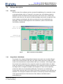
Flexiva automation & Robotik GmbH
Weißbacher Straße 3
D – 09439 Amtsberg
User Manual DC/AC-Module PM3AC10-1x
Operation
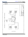
5.6.5
Multiple Modules at the Network
In the mains operation, it is possible to connect several modules in parallel or to
distribute them to several phases. Example c) shows such a parallel connection. If the
DC link voltage is constant and is not regulated by the AC modules, the current of
every AC module can be set individually by means of its a_isoll. If the DC link voltage
is to be regulated by the AC modules, it is important to parameterize the same falling
characteristic for the DC link voltage regulator by means of the parameters zk_fkkp
and zk_fkkt at all modules in order to get an even load distribution.
c)
ZK
ZK
DC
DC
AC
L1
AC
Mains
DC
AC
application
any application
parameter
mod_opmode:
DC/ACmodule at
the mains
Mains
DC
L2
AC
N
0b00000010=2 / 0b00001010=10
0b00010010=18 / 0b00011010=26
zk_usoll/zk_usollv:
desired lower dc link voltage, has to be smaller than
the minimum dc link voltage in the system
zk_usollh/zk_usollvh: desired upper dc link voltage, has to be bigger than
the maximum dc link voltage in the system
a_isoll:
desired output current
a_fsoll:
mains frequency
a_usoll:
mains voltage
a_phase/a_iblind_soll phase / reactive current, dep. on mod_opmode bit 4
5.6.6
Single Module in Island Operation
Example d) shows the application of the AC module in island operation. The DC link
voltage regulation of the AC module reduces the output voltage if the DC link voltage
remains under the desired value of the DC link of the AC module zk_usoll and/or
zk_usollv. This is, for example, the case when the source is no longer able to feed the
Flexiva automation & Robotik GmbH
Weißbacher Straße 3
D – 09439 Amtsberg
41
User Manual DC/AC-Module PM3AC10-1x
Operation
load. If this condition lasts longer than 10s, a fault shutdown is carried out because of
undervoltage.
VS
d)
ZK
DC
Source
5.6.7
ZK
DC
DC
AC
Load
application
any application
parameter
mod_opmode:
1
DC/DCmodule at
the source
vs_imax:
+ desired current limit
vs_imin:
0
zk_usoll:
desired dc link voltage
vs_usoll:
smaller than the minimum voltage (of the source)
parameter
mod_opmode:
DC/ACmodule at
the load
0b00000000=0 oder 0b00000001=1
0b00001000=8 oder 0b00001001=9
zk_usoll/zk_usollv:
desired dc link voltage, has to be smaller than
the minimum dc link voltage in the system
a_usoll:
desired output voltage
a_fsoll:
desired frequency
Parallel Operation in Island Operation
In example e), the parallel connection of several modules in island operation is
shown. The first module (master) is normally parameterized for the island operation.
As far as the slave modules are concerned, bit 5 must be set in mod_opmode in order
to enable them to synchronize themselves via the SYNC_IN input.
If bit 0=1 is set in mod_opmode and consequently the resonant PI regulator is
activated, an internal resistance has to be parameterized for an even load distribution
(parameter a_kri). The desired values of the output voltage of all DC/AC modules
involved have to be parameterized identically. The phase relation has to be
parameterized to the same value (recommended all to 0) at all modules, too.
During the switching-on, it has to be paid attention to the fact that the master module
is switched on first and the slave modules are switched in after a short waiting time.
42
Flexiva automation & Robotik GmbH
Weißbacher Straße 3
D – 09439 Amtsberg
User Manual DC/AC-Module PM3AC10-1x
Operation
e)
ZK
MASTER
SL AVE
SL AVE
DC
DC
DC
SYNC_ OU T
SYNC_ OU T
SYNC_ IN
SYN C_IN
AC
N
AC
L
N
AC
L
N
L
Load
application
any application
parameter
mod_opmode:
(master)
0b00000000=0 oder 0b00000001=1
0b00001000=8 oder 0b00001001=9
mod_opmode:
(all slaves)
0b00100000=32 oder 0b00100001=33
0b00101000=40 oder 0b00101001=41
zk_usoll/zk_usollv:
desired dc link voltage, has to be smaller than
the minimum dc link voltage in the system
a_usoll:
desired output voltage
Must be the same for all modules!
a_fsoll:
desired frequency
a_phase:
0
a_kri:
10 per 1 Ohm, if bit 0 in mod_opmode is set
DC/ACmodule at
the mains
Flexiva automation & Robotik GmbH
Weißbacher Straße 3
D – 09439 Amtsberg
43
User Manual DC/AC-Module PM3AC10-1x
Operation
5.6.8
Multiphase System in Island Operation
For the setting-up of a multiphase island system, the master module has to be
configured for the normal island operation. As far as the slave modules are
concerned, the bits 5 and 6 must be set in mod_opmode. Bit 5 for the synchronization
via SYNC_IN, bit 6 for the multiphase operation, in case of which neither the
existence of voltage at the module nor the phase relation of it are checked before the
switching-in. The outputs SYNC_OUT are in phase with SYNC_IN each if the
synchronization was successful. The phase displacement of the individual modules is
fixed by means of the parameter a_phase. Consequently, the angles 0°, +120° and –
120° have to be parameterized for a three-phase network.
f)
ZK
MASTER
SLAVE
DC
SLAVE
DC
DC
SYNC_ OU T
SYNC _OUT
SYNC _IN
AC
N L1
SYNC_ IN
AC
N L2
AC
N L3
Load
3~
application
any application
parameter
mod_opmode:
(master)
0b00000000=0 oder 0b00000001=1
0b00001000=8 oder 0b00001001=9
mod_opmode:
(all slaves)
0b01100000=96 oder 0b01100001=97
0b01101000=104 oder 0b01101001=105
zk_usoll/zk_usollv:
desired dc link voltage, has to be smaller than
the minimum dc link voltage in the system
a_usoll:
desired output voltage
a_fsoll:
desired frequency
a_phase:
0, +120° -120°
DC/ACmodule at
the mains
44
Flexiva automation & Robotik GmbH
Weißbacher Straße 3
D – 09439 Amtsberg
User Manual DC/AC-Module PM3AC10-1x
Operation
5.7
Error Handling
Acknowledging of the error, eliminating of the cause, restarting.
Flexiva automation & Robotik GmbH
Weißbacher Straße 3
D – 09439 Amtsberg
45
User Manual DC/AC-Module PM3AC10-1x
Programming / Parameterization
6
Programming / Parameterization
6.1
Preliminary Remarks
The DC/AC module offers a convenient software interface. All parameters /
commands / measured values can be written and/or read by means of a simple ASCII
protocol. All module variables no matter whether they represent a parameter, a
measured value or a command are addressable by means of an instruction code
consisting of two characters. The first character indicates the respective group
membership, e.g. "z“ for the voltage parameters of the DC link and the second
character then specifies the concrete variable. A complete list of all instruction codes
is part of the present documentation.
The serial interface of the modules serves as (hardware) communication interface. It
can, for example, be connected with the RS232 interface of a PC. The following
settings are required:
Bits per Second
Data bits
Parity
Stop bits
Flow control
Tab. 8:
46
115200
8
None
1
None
Settings RS232
Flexiva automation & Robotik GmbH
Weißbacher Straße 3
D – 09439 Amtsberg
User Manual DC/AC-Module PM3AC10-1x
Programming / Parameterization
6.2
The ASCII Protocol used
The transfer of the corresponding commands in the ASCII format is done in a simple
scheme. All characters transferred to the module are immediately evaluated by the
same and checked with regard to their validity within the respective sequence of
commands. This means concretely: If, for example, a plus/minus sign is expected at
a certain point of a sequence of commands, the module only accepts the signs
plus(+) or minus(-). Valid characters are directly mirrored (exceptions: control
characters for the protocol changeover and CR), invalid characters are immediately
rejected. With the aid of this procedural method, a complex and extensive protocol
(checksums, length specifications etc.) can be avoided and, nevertheless, faulty
insertions can be minimized.
From firmware 2.13 on, a protocol with checksum is available (see further chapter).
6.2.1
Read / write without checksum
Basically, you have to distinguish between "Reading" and "Writing" as far as the
sequences of instructions to be sent to the module are concerned. If, for example, the
value stored in a module variable is only to be read, you have to send the
corresponding command code as a sequence followed by Return. If a new value is to
be stored in a variable, the corresponding command code, the plus/minus sign of the
new value, the new value itself and Return are to be sent.
Read
Command code + CR
Write
Command code + sign + new value + CR
Tab. 9: Command sequences without checksum in general
6.2.2
Read / write with checksum
Basically, you have to distinguish between "Reading" and "Writing" as far as the
sequences of instructions to be sent to the module are concerned. If, for example, the
value stored in a module variable is only to be read, you have to send the
corresponding command code as a sequence followed by Return. If a new value is to
be stored in a variable, the corresponding command code, the plus/minus sign of the
new value, the new value itself, the checksum and Return are to be sent.
Read
Command code + Σ + CR
Tab. 10:
Write
Command code + sign + new value + Σ + CR
Command sequences with checksum in general
The following table lists all possible command codes for the communication with the
module and they are arranged in groups. At the same time, the names of the
respective module variables as well as the place of storing and the parameterability
are shown.
Flexiva automation & Robotik GmbH
Weißbacher Straße 3
D – 09439 Amtsberg
47
User Manual DC/AC-Module PM3AC10-1x
Programming / Parameterization
Group
DC link
(DC link side)
Output
(AC side,
(component
side)
Temperatures
Info
Commands
Oscilloscope
x+
Description
voltage, normal range: lower regulator, desired value
2. Command
Character
parametrizable
z
u
x+
stored in
EEPROM
Parameter
zk_usoll
voltage, normal range: lower regulator, desired initial value in EEPROM
z
v
x
voltage, normal range: upper regulator, desired value
z
s
x+
voltage, normal range: upper regulator, desired initial value in EEPROM
z
t
x
voltage, full range: lower regulator, desired value
z
q
x+
voltage, full range: lower regulator, desired initial value in EEPROM
z
r
x
voltage, full range: upper regulator, desired value
z
o
x+
voltage, full range: upper regulator, desired initial value in EEPROM
z
p
x
voltage, normal range: actual value
z
a
zk_uist
voltage, full range: actual value
z
b
zk_uistv
voltage: upper limit (not used)
z
m
x
x
zk_umax_g
voltage: lower limit (not used)
z
n
x
x
zk_umin_g
x
zk_usoll_f
x
zk_usollh_f
zk_usollh
zk_usollv
x
zk_usollv_f
zk_usollvh
x
zk_usollvh_f
regulator: I-component
y
i
x
x
zk_ki
regulator: P-component
y
p
x
x
zk_kp
regulator: time constant
y
t
x
x
zk_kt
voltage window for the gain increase
y
f
x
x
zk_uf
gain increase outside the voltage window
y
v
x
x
zk_kv
falling characteristic ("internal resistance"): gain
y
k
x
x
zk_fkkp
falling characteristic ("internal resistance"): filter time constant
y
z
x
x
zk_fkkt
x
a_fsoll_f
frequency: desired value
w
f
x
frequency: desired initial value in EEPROM
w
g
x
a_fsoll
frequency: actual value
w
h
phase angle: desired value
w
p
phase angle: desired initial value in EEPROM
w
q
x
current: desired value
w
i
x+
current: desired initial value in EEPROM
w
j
x
reactive current: desired value
w
k
x+
reactive current: desired initial value in EEPROM
w
l
x
voltage: desired value
w
u
x+
voltage: desired initial value in EEPROM
w
v
internal resistance: desired value
w
z
voltage: r.m.s. value of the output, measured value
v
u
voltage: r.m.s. value of the mains, measured value
v
w
n_ueff
current: r.m.s. value, measured value
v
i
a_ieff
a_fist
x
a_phase
x
a_phase_f
x
a_isoll_f
x
a_iblind_soll_f
x
x
a_usoll_f
x
x
a_kri
a_isoll
a_iblind_soll
a_usoll
a_ueff
power: actual value
v
p
a_p
voltage: DC component
v
d
a_udc
current: actual amplitude value (mains operation)
v
j
a_iampl
voltage: actual amplitude value (island operation)
v
v
a_uampl
heat sink
t
k
t_kk
module state
i
s
module operating mode
i
m
module type
i
t
module firmware
i
f
module serial number
i
n
x
module date of manufacture
i
d
x
mod_state
x
x
mod_opmode
module on / off
c
e
x+
mod_on
acknowledge an error
c
q
x
err_quit
communication mode
c
c
com_mode
channel
o
k
x+
osz_ch
frequency divider
o
f
x+
osz_ft
trigger value
o
t
x+
osz_tr
trigger channel
o
c
x+
osz_tch
storage mode
o
m
x+
osz_m
oscilloscope on / off
o
e
x+
osz_on
read data (only the channel osz_ch)
o
r
read data (all channels)
o
s
also parametrizable, if the module is switched on (mod_on=1)
Tab. 11:
48
1. Command
Character
Complete table of the command codes
Flexiva automation & Robotik GmbH
Weißbacher Straße 3
D – 09439 Amtsberg
User Manual DC/AC-Module PM3AC10-1x
Programming / Parameterization
6.2.3
ASCII-long / ASCII-short
On the part of the module answer, two protocol variants are possible: "long" and
"short" ASCII protocol. ASCII-long is particularly suited for the manual entry of
instructions, e.g. by using a terminal program such as "HyperTerminal" from
Windows. When this protocol is set, the module sends any information and (error)
messages in clear text and sees to a distinct representation in the terminal program
by means of the transfer of CR and NL control characters at corresponding points.
On the other hand, the protocol ASCII-short should be used when the instruction is to
be handed over from another software such as, for example, from the software
"ModuleConfigSuite" of Flexiva. If this protocol is set, any information and (error)
messages in clear text are suppressed. In case of an error, only error codes are
transferred.
ASCII-long
- command code + CR + NL
without
- sign + readout value + CR + NL
error
- „OK“ + CR + NL + NL
with
error
- command code + CR + NL
- error code + CR + NL
- error text + CR + NL + NL
Tab. 12:
ASCII-short
- command code + CR
- sign + readout value + CR
- command code + CR
- error code + CR
Module answer for the reading of a parameter / value
ASCII-long
ASCII-short
- command code + sign + new value + CR + NL
without
- sign + read back value + CR + NL
error
- „OK“ + CR + NL + NL
- command code + sign + new value + CR
- sign + read back value + CR
- command code + sign + new value + CR + NL
- error code + CR + NL
- error text + CR + NL + NL
- command code + sign + new value + CR
- error code + CR
with
error
Tab. 13:
Module answer for the writing of a parameter / value
Flexiva automation & Robotik GmbH
Weißbacher Straße 3
D – 09439 Amtsberg
49
User Manual DC/AC-Module PM3AC10-1x
Programming / Parameterization
6.2.4
ASCII-short with checksum
Starting with firmware 2.13 a communication protocol with checksum is available.
This is based on the existing protocol "ASCII-short". However, a 1-byte checksum is
used now instead of resending each character received for error checking. This
checksum is transmitted in each case as the last character before the CR (dec. 13) in
both directions of communication.
The checksum is calculated as the sum of all transmitted bytes modulo 256. If the
result is randomly 13, it is replaced by 14 in order to avoid collisions with the CR (dec.
13) as an input terminator.
ASCII-short with checksum
without
error
with
error
- command code + Σ + CR
- sign + read back value + Σ + CR
- command code + Σ + CR
- error code + Σ + CR
Tab. 14:
Module answer during reading of a parameter / value
ASCII-short with checksum
without
error
with
error
- command code + sign + new value + Σ + CR
- sign + read back value + Σ + CR
- command + sign + new value + Σ + CR
- error code + Σ + CR
Tab. 15:
Module answer during writing of a parameter / value
When reading the data from the oscilloscope no checksum is transmitted. Here, the
data transmission is as in the ASCII-short protocol.
50
Flexiva automation & Robotik GmbH
Weißbacher Straße 3
D – 09439 Amtsberg
User Manual DC/AC-Module PM3AC10-1x
Programming / Parameterization
6.2.5
Switching between the protocols
The changeover between the protocol variants is executed by putting a command
character in front of the respective first sequence of commands. This command
character can also be sent separately. The respective protocol setting is preserved
until the next protocol changeover and/or to the next restart (supply voltage gone) or
reset of the module. As a standard setting, ASCII-short is set.
Protocol-option
ASCII-short
ASCII-long
ASCII-short with checksum
Tab. 16:
Flexiva automation & Robotik GmbH
Weißbacher Straße 3
D – 09439 Amtsberg
Control character to the module
$
%
&
Protocol changeover
51
User Manual DC/AC-Module PM3AC10-1x
Programming / Parameterization
6.2.6
Concrete example
To explain the above-mentioned paragraphs, the sequences of instructions to be
transferred to the module and the corresponding answers of the module are listed in
the following at a concrete example. The case without errors is treated.
The module variable zk_umin_g is to be read-out and a new value is to be stored in it.
The corresponding code is "zn", the old value in the variable is "+3500" and the new
value is "+3600". This results for the two ASCII modes in the following communication
with the module:
6.2.6.1 ASCII-long
To the Module
ASCII
%
z
n
HEX
25 7A 6E
From the Module
ASCII
z
n
HEX
7A 6E
CR
OD
CR
0D
NL
0A
+
2B
3
33
5
35
0
30
Tab. 17:
To the Module
ASCII
%
z
n
HEX
25 7A 6E
From the Module
ASCII
z
n
HEX
7A 6E
0
30
CR
0D
NL
0A
O
4F
K
4B
CR
0D
NL
0A
NL
0A
Reading ASCII-long
+
2B
3
33
6
36
0
30
0
30
CR
0D
+
2B
3
33
6
36
0
30
0
30
CR
0D
NL
0A
Tab. 18:
+
2B
3
33
6
36
0
30
0
30
CR
0D
NL
0A
O
4F
K
4B
CR
0D
NL
0A
NL
0A
Writing ASCII-long
6.2.6.2 ASCII-short
To the Module
ASCII
$
z
n
HEX
24 7A 6E
From the Module
ASCII
z
n
HEX
7A 6E
CR
OD
CR
0D
+
2B
3
33
5
35
0
30
0
30
Tab. 19:
To the Module
ASCII
$
z
n
HEX
24 7A 6E
From the Module
ASCII
z
n
HEX
7A 6E
52
Reading ASCII-short
+
2B
3
33
6
36
0
30
0
30
CR
0D
+
2B
3
33
6
36
0
30
0
30
CR
0D
Tab. 20:
CR
0D
+
2B
3
33
6
36
0
30
0
30
CR
0D
Writing ASCII-short
Flexiva automation & Robotik GmbH
Weißbacher Straße 3
D – 09439 Amtsberg
User Manual DC/AC-Module PM3AC10-1x
Programming / Parameterization
6.2.6.3 ASCII-short with checksum
To the Module
ASCII
&
z
n
HEX
26 7A 6E
From the module
ASCII
HEX
Σ
E8
CR
0D
+
2B
3
33
Tab. 21:
To the Module
ASCII
&
z
n
HEX
26 7A 6E
From the Module
ASCII
HEX
+
2B
3
33
6
36
5
35
0
30
0
30
Σ
F3
Reading ASCII-short with checksum
0
30
0
30
Σ
DC
CR
0D
+
2B
Tab. 22:
CR
0D
3
33
6
36
0
30
0
30
Σ CR
F4 0D
Writing ASCII-short with checksum
For computing the checksum the gray values are added. The residue left in the
Division by 256 is the checksum. If this value is 13, it is replaced with 14.
char checksum;
...
checksum = 0;
for (i = 0; i < idx; i++) checksum = checksum + buf[i];
if (checksum == 13) checksum = 14;
...
Tab. 23:
Flexiva automation & Robotik GmbH
Weißbacher Straße 3
D – 09439 Amtsberg
Example for computing the checksum in C
53
User Manual DC/AC-Module PM3AC10-1x
Programming / Parameterization
6.2.7
Error messages during the communication
All sequences arriving in the module are immediately checked and processed. The
following errors can occur during the reading / writing and these errors concern
exclusively the parameterizing process and are not to be confused with the errors that
may arise during the operation of the module and are coded in the status variable
mod_state (Tab. 5):
Error code
E0
E1
E2
E3
E4
E5
E6
E7
E8
E9
Meaning in clear text
Reserve
Reserve
Invalid module command
Value is out of range
Value is read only
Device must be switched off
Not used
Not used
Min-value must be smaller than the max-value
Checksum error
Tab. 24:
54
Error messages
Flexiva automation & Robotik GmbH
Weißbacher Straße 3
D – 09439 Amtsberg
User Manual DC/AC-Module PM3AC10-1x
Programming / Parameterization
6.3
Communication by Means of a Terminal Software
Because of the utilization of an ASCII protocol for the communication interface, a
communication with the module is possible by means if any terminal software you
like. As an example, HyperTerminal is mentioned here that is part of the older (below
windows7) windows versions (see Fig. 8). Of course, every other software can be
also applied (Freeware, self-developed software) by means of which a bidirectional
serial communication is possible. For the utilization of terminal software, the protocol
setting ASCII-long is recommended.
Fig. 8: Module parameterization by means of a terminal software
6.4
Communication by Means of ModuleConfigSuite
Another and much more convenient possibility is the utilization of the Windows
software "ModuleConfigSuite" from the company Flexiva that is contained in the
scope of delivery of the inverter module as a standard component. This software
permits a convenient communication and a closed access (parameterizing /
monitoring / storing) to all variables (parameters / commands / measured values) of
every single module. Furthermore, it is possible to communicate simultaneously with
up to 4 modules. The ModuleConfigSuite uses the protocol setting ASCII-short
Flexiva automation & Robotik GmbH
Weißbacher Straße 3
D – 09439 Amtsberg
55
User Manual DC/AC-Module PM3AC10-1x
The Parameterizing Software "ModuleConfigSuite"
7
The Parameterizing Software "ModuleConfigSuite"
7.1
Preliminary Remarks
A Windows-software for the PC is supplied along with the module. It is intended for
the convenient parameterization and visualization of all parameters / commands /
measured values as well as for the recording of selected data on the PC. In the
following, details concerning the function and operation of this software are explained.
System requirements
Hardware:
- customary PC of medium performance and RS232 interface
Operating system:
- MS Windows (from Windows XP SP2 onwards)
7.2
Installation
The software is installed like any other conventional Windows software:
1. Insert the data carrier.
2. Start the installation by means of starting the file setup.exe.
3. Follow the instructions given by the installation program (path entry etc.).
a. Installation step backwards by means of a click onto Back
b. Installation step forwards by means of a click onto Next
c. Stop the installation by means of a click onto Cancel
4. Terminate the installation by means of a click onto Finish
7.3
Deinstallation
If the software is to be removed from the PC, you proceed as follows:
1. Open the Start menu of Windows.
2. Select System control.
3. In the system control panel click onto the symbol Software.
A list of the available programs is displayed.
4. Select from the list the symbol for ModuleConfigSuite.
5. Click onto Remove. The software is de-installed now.
56
Flexiva automation & Robotik GmbH
Weißbacher Straße 3
D – 09439 Amtsberg
User Manual DC/AC-Module PM3AC10-1x
The Parameterizing Software "ModuleConfigSuite"
7.4
Software description
7.4.1
Overview
After the start of the software and the successful establishing of a connection to one
or several modules (click on "Connect!" in the menu line), the following window is
displayed in which a division into three parts that is into a menu line, a button bar
directly under the menu line and the remaining display area can be recognized. Only
those modules are displayed with which a connection is to be established (see
paragraph "Selection and Assignment of the Interfaces“) and a connection was
successfully established.
Menu line
Button bar
Remaining
display aread
Fig. 9:
7.4.2
Basic structure of the software
Single-Mode / Multi-Mode
On principle, the software distinguishes between two modes, the so-called "Single"mode for the communication with only one single module and the so-called "Multi"mode for the simultaneous communication with up to 4 modules. In the Single-mode,
the access to all parameters of the respective module is possible while in the Multimode, the access only to selected parameters of the respective module is possible. In
the Single-mode, the digital nameplate and temperature values of the respective
module are read-out and visualized additionally. Furthermore, an oscilloscope
function and a selection aid for the fixing of the mode of operation (mod_opmode) are
available. The changeover between the modes is executed by means of the buttons
in the upper window area. After the start of the software, the Multi-mode is
automatically set.
Flexiva automation & Robotik GmbH
Weißbacher Straße 3
D – 09439 Amtsberg
57
User Manual DC/AC-Module PM3AC10-1x
The Parameterizing Software "ModuleConfigSuite"
Fig. 10:
Fig. 11:
58
Single-mode / module 3
Multi-mode
Flexiva automation & Robotik GmbH
Weißbacher Straße 3
D – 09439 Amtsberg
User Manual DC/AC-Module PM3AC10-1x
The Parameterizing Software "ModuleConfigSuite"
7.4.3
Groupings by Means of Colours / Backgrounds
Owing to the great number of information to be represented at the same time and the
diversity of the entries to be processed, the application of different colors for the
logical grouping turned out to be advantageous. The legend with the explanation of
the colors can be called after the selection of the menu item "Help Color Codes".
Fig. 12: Example for groupings
Flexiva automation & Robotik GmbH
Weißbacher Straße 3
D – 09439 Amtsberg
Fig. 13 :
Color legend
59
User Manual DC/AC-Module PM3AC10-1x
The Parameterizing Software "ModuleConfigSuite"
7.4.4
Meaning of the Error Codes
All data that are transferred (for example, by a click onto one of the buttons "Write
Values" in the single-mode) to the module, are immediately checked there with regard
to their validity. In case of an error, the corresponding error code is entered in a red
field directly next to the respective display / entry element. A table with the meaning of
the error codes can be retrieved by selection of the menu item „Help Error Codes“.
Fig. 14: Example of error codes
7.4.5
Fig. 15: Meaning of the error codes
Selection and Assignment of the Interfaces
The selection of the interfaces and their assignment to the modules is carried out by
the selection of the menu item "Settings Connection". Depending on the type of the
module carrier, there are various possibilities available. In case of the module carrier
of the type 1, the communication is executed by means of 4 separate RS232
interfaces (one for every module). The module carrier of the type 2 needs only one
RS232 for the communication with all modules (is multiplexed in the module carrier).
In addition to the assignment of the interfaces, you also have to select explicitly by
marking a checkbox in the configuration dialogue whether communication with the
respective module is intended. This offers the possibility to include the individual
modules in the communication or not.
During the selection and assignment of the rs232 interfaces, tests are carried through
concerning the existence in the PC and/or availability.
60
Flexiva automation & Robotik GmbH
Weißbacher Straße 3
D – 09439 Amtsberg
User Manual DC/AC-Module PM3AC10-1x
The Parameterizing Software "ModuleConfigSuite"
Fig. 16: Assignment of the interface
Attention: Only a test of the chosen interfaces and their assignment to the modules is
made. The data connection to the modules is only established after the selection of
the menu item "Connect!".
7.4.6
Connecting / Disconnecting
By the selection of the menu item "Connect!" it is possible to establish a data
connection to the corresponding module (single-mode) and/or to the modules multimode). In the single-mode, all data are read-out once completely from the chosen
module after the successful establishing of the connection and entered into the
respective fields of the screen mask. In the multi-mode, only the relevant data are
read-out after the successful establishing of the connection and entered into the
respective fields of the screen mask. A selection of the menu item "Disconnect!"
cut(s)-off the connection(s).
Fig. 17: Information in case of the cutting-off of the connection
Flexiva automation & Robotik GmbH
Weißbacher Straße 3
D – 09439 Amtsberg
61
User Manual DC/AC-Module PM3AC10-1x
The Parameterizing Software "ModuleConfigSuite"
The connection is permanently monitored both during the establishing of the
connection and during the existing connection. If the establishing of the connection
fails and/or the connection is cut-off a corresponding hint appears.
7.4.7
Storing / Loading of Parameter Sets
In the single-mode, it is possible to store parameter sets on the PC and/or to load
parameter sets that are stored on the PC. After the calling of the menu items "File
Load Parameter Set" and/or "File Save Parameter Set", the corresponding
dialogues are called for the loading and storing of files. The parameter files have got
a special format that can only be read and write by the ModuleConfigSuite.
Fig. 18: Dialogue for the loading of parameter files
When such a file is loaded from the PC, all parameters are immediately entered into
the corresponding fields. In the reverse case, only the corresponding fields are readout for the storing of the parameters in such a file. Only such fields with the respective
colored background are taken into account.
7.4.8
Reading-Out / Parameterization
All relevant data are automatically read-out from the module and/or the modules
during the changeover between the two main modes single-mode and multi-mode
(buttons: "Modules 1…4" and "M1" … "M4") or during the establishing of the
connection ("Connect!"). In the single-mode, all data are read-out from the selected
module and entered into the corresponding fields of the screen mask, in the multimode only the relevant ones. The requirement is in both modes an existing data
62
Flexiva automation & Robotik GmbH
Weißbacher Straße 3
D – 09439 Amtsberg
User Manual DC/AC-Module PM3AC10-1x
The Parameterizing Software "ModuleConfigSuite"
connection to the respective module and/or to the respective modules.
In addition to that, it is possible in the single-mode to explicitly initiate the reading-out
of the data from the module and/or the storing of data in the module by means of a
click onto one of the buttons "Read Values" or "Write Values". Only the data of the
respective column (e.g. "DC link") are taken into account during this.
Fig. 19: Buttons for the reading-out / parameterization in the single-mode
Both in the single-mode and in the multi-mode, some data are immediately
transferred after their entry / modification (see color codes). These are in particular
the parameters: a_isoll, a_usoll, zk_usoll (zk_usollv) and zk_usollh (zk_usollvh).
7.4.9
Data Visualization / Recording
In the single-mode as well as in the multi-mode, in case of an existing connection, the
parameters a_ueff, n_ueff, a_ieff, zk_uist (zk_uistv) and mod_state are permanently
read-out and visualized with a transfer rate of approx. 10 Hz when the connection
exists. If the check boxes "Charts" and "Save" are marked, in addition to that, the
parameters a_ueff, n_ueff, a_ieff, zk_uist (zk_uistv) are simultaneously visualized in
diagrams and data are stored (data-logging) in the ASCII format.
Fig. 20: Dialogue field storing / visualizing
Flexiva automation & Robotik GmbH
Weißbacher Straße 3
D – 09439 Amtsberg
zk_uist
a_ieff
a_ueff
n_ueff
3698
3698
3697
3698
3697
3697
3697
3697
3697
3697
3697
3697
3697
3696
3696
69
69
69
69
69
69
69
69
69
69
69
69
69
69
69
2231
2231
2231
2231
2231
2231
2231
2231
2229
2231
2231
2231
2231
2231
2231
2218
2218
2218
2218
2218
2218
2218
2218
2218
2218
2218
2218
2220
2218
2218
Fig. 21: Recorded ASCII data
63
User Manual DC/AC-Module PM3AC10-1x
The Parameterizing Software "ModuleConfigSuite"
During every new establishing of a connection by means of a click onto "Connect!"
and a marked "Save", a new data file (a separate one for every module) in the ASCII
format with the file extension *.asc is automatically generated in the working directory
of the ModuleConfigSuite. For this purpose, it does not matter whether you are in the
single-mode or in the multi-mode. The file names of the generated files are composed
of the module code as well as date and time of the beginning of the recording.
Consequently, the file name “M3_110406_114231.asc“ designates a data recording
of the module 3 that started on 11th April 2006 at 11:42:31 a.m.
For safety reasons, the data are stored only in the corresponding mode (single-/
multi-) respectively in the single-mode only for the module just selected. If, for
example, the storing is marked for all 4 modules in the multi-mode, only a storing of
the data in the file of the corresponding chosen module is carried out in the singlemode and no (background) storing of the data of all 4 modules is executed. Singlemode and multi-mode store to the same data file of the respective module.
64
Flexiva automation & Robotik GmbH
Weißbacher Straße 3
D – 09439 Amtsberg
User Manual DC/AC-Module PM3AC10-1x
The Parameterizing Software "ModuleConfigSuite"
7.4.10
Selecting of the Mode of Operation
In the Single-mode, it is possible to select the required mode of operation in a simple
way. By means of simple dialogue field (invocation by means of button "selection" in
the field "mod_opmode“), all bits of the parameter mod_opmode and their
dependencies from each other are visualized and the corresponding decimal value of
the parameter mod_opmode is calculated. After clicking "Apply", this value is applied
and stored in the module.
Fig. 22: Dialogue for the selection of the mode of operation
Flexiva automation & Robotik GmbH
Weißbacher Straße 3
D – 09439 Amtsberg
65
User Manual DC/AC-Module PM3AC10-1x
Maintenance service and repairs by the customer service
8
Maintenance service and repairs by the customer service
According to the general terms and conditions of sale and delivery, WARRANTY is
furnished for the device provided by the manufacturer. If malfunctions or damages
occur at the device during the warranty period warranty is given for according to the
terms and conditions of warranty, the manufacturer shall execute the repair or the
replacement of defective components after a prior examination.
The manufacturer shall be responsible for the device in its original configuration.
Only the manufacturer shall be authorized to carry out all and any interventions that
concern the device, the structure, the software, or the operating cycle of the device or
these interventions exclusively require the express prior consent of the manufacturer.
Attention
The environmental conditions agreed in the contract must be met.
The manufacturer shall not be liable for any damages owing to the improper or false
utilization of the device as well owing to damages arising from interventions to the
device that are not expressly required in the present manual.
66
Flexiva automation & Robotik GmbH
Weißbacher Straße 3
D – 09439 Amtsberg
User Manual DC/AC-Module PM3AC10-1x
Appendix
9
Appendix
Flexiva automation & Robotik GmbH
Weißbacher Straße 3
D – 09439 Amtsberg
67
FLEXIVA automation & Robotik GmbH
Weißbacher Straße 3
09439 Amtsberg
Telefon: +49 37209 671 0
Telefax: +49 37209 671 30
www.flexiva.eu
[email protected]