1
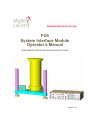
FG5
System Interface Module
Operator’s Manual
WITH REMOTE OPERATION PACKAGE INSTRUCTIONS
MARCH, 2006
Micro-g LaCoste Tele-g Remote Operation User’s Manual
TABLE OF CONTENTS
TABLE OF FIGURES...................................................................................................... 3
1
INTRODUCTION..................................................................................................... 4
1.1
1.2
1.3
2
DESIGN ................................................................................................................ 4
COMPONENTS ...................................................................................................... 4
APPLICATION EXAMPLES ..................................................................................... 4
HARDWARE ............................................................................................................ 5
2.1
THE “SYSTEM INTERFACE MODULE” ................................................................... 5
2.1.1
The Outputs................................................................................................. 5
2.1.2
The Dropper Controller.............................................................................. 6
2.1.3
The Superspring Controller ........................................................................ 8
2.1.4
The System Leveling Controller.................................................................. 9
2.1.5
The Tele-g and g Software Interfaces ....................................................... 10
2.2
ASSEMBLING THE SUPERSPRING AUTO-LEVELING TRIPOD ................................ 12
2.3
SETTING UP THE TELE-G ENABLED FG5 GRAVIMETER ...................................... 13
2.4
THE TILT METERS .............................................................................................. 14
3
SOFTWARE – TELE-G ......................................................................................... 15
3.1
3.2
3.3
3.4
3.5
3.6
4
INTRODUCTION .................................................................................................. 15
STARTING TELE-G .............................................................................................. 15
SUPERSPRING CONTROL ..................................................................................... 15
LEVEL CONTROL ................................................................................................ 16
DROPPER CONTROL ........................................................................................... 17
A2D SETUP ........................................................................................................ 19
SOFTWARE – THIRD PARTY............................................................................ 20
4.1
INTRODUCTION .................................................................................................. 20
4.2
“VNC” VIRTUAL NETWORK COMPUTING .......................................................... 20
4.2.1
Setting up the VNC Server on the System Controller ............................... 21
4.2.2
Setting up the VNC Viewer ....................................................................... 22
4.3
“SSH” SECURE SHELL FOR CONNECTIONS THROUGH FIREWALLS ..................... 22
2
Micro-g LaCoste Tele-g Remote Operation User’s Manual
Table of Figures
FIGURE 1. THE OUTPUT PORTION OF THE SIM. THIS PROVIDES AN OUTPUT OF THE ANALOG
FRINGE SIGNAL, AND CONNECTIONS TO AN (OPTIONAL) ML 1 LASER........................... 5
FIGURE 2. DROPPER CONTROLLER SECTION OF THE SYSTEM INTERFACE MODULE............ 6
FIGURE 3. SUPERSPRING PORTION OF THE SYSTEM INTERFACE MODULE............................ 8
FIGURE 4. AUTO-LEVELING PORTION OF SYSTEM INTERFACE MODULE. .......................... 10
FIGURE 5. THE "TELE-G" AND "G" SOFTWARE INTERFACE................................................ 11
FIGURE 6. SUPERSPRING ON AUTO-LEVELING TRIPOD...................................................... 12
FIGURE 7. SUPERSPRING TRIPOD DURING ASSEMBLY. THE Y LEG IS SHOWN WITHOUT THE
FOOT. BEFORE SNAPPING THE FEET IN PLACE IT IS NECESSARY TO INSERT AND TIGHTEN
THE LOCK NUTS (SHOWN IN PURPLE). ......................................................................... 13
FIGURE 8. IOTECH INITIALIZATION SCREEN IN TELE-G. .................................................... 15
FIGURE 9. SUPERSPRING CONTROL WINDOWS IN TELE-G. ................................................. 16
FIGURE 10. LEVEL CONTROL WINDOWS IN TELE-G. THE RED CURVE SHOWS THE TILT
ABOUT THE X AXIS AND THE BLUE CURVE SHOWS THE TILT ABOUT THE Y................. 17
FIGURE 11. DROPPER CONTROLLER WINDOW IN TELE-G................................................... 18
FIGURE 12. A2D SETUP SCREEN IN TELE-G....................................................................... 19
FIGURE 13. VNC DISPLAY WITH TELE-G RUNNING ON A REMOTE COMPUTER. .................. 21
FIGURE 14. SSH SETUP FOR CONNECTING THROUGH A FIREWALL. ................................... 23
FIGURE 15. VNC/SSH TUNNELING DIAGRAM. .................................................................. 24
3
Micro-g LaCoste Tele-g Remote Operation User’s Manual
1 INTRODUCTION
1.1 Design
The Tele-g Remote Gravimeter Operation system is designed to allow remote access to
the system controller (computer) of a gravity meter. In addition to accessing g, the
gravity measurement software, the system has its own software package Tele-g that
allows the monitoring of a large portion of the system components. These include:
• The system tilt (verticality)
• Superspring position
• Superspring mode
• Dropper “tuning”
• Dropper mode
• Interferometric fringe amplitude measurement
In addition, a few parameters can be adjusted through the Tele-g interface. These
include
• Resetting the tilt position (and thus verticality) back to zero.
• Changing the superspring position
• Enabling/Disabling the Superspring servo
• Changing the dropper controller mode
1.2 Components
The complete Remote Gravimeter Operation system is comprised of hardware upgrades
to an FG5 gravimeter, an electronic component known as the System Interface Module
(SIM), and the Tele-g software program. In addition, to facilitate networking the system
controller for remote access, two additional third-party software packages can be used.
1.3 Application Examples
The Remote Gravimeter Operation system is designed for either long or short term
monitoring of a remote FG5. The system can be used to verify that a meter set up to run
for a long (weeks) period of time is still functioning. The user can check system tilt
(verticality) and make adjustments to it. The user can also reset the Superspring position,
if necessary. And if the system stops due to a power outage or a hardware reset, in most
cases it can be restarted remotely.
Even for short (overnight) applications, the system is highly useful. In time critical
surveys the meter can be “checked in on” to verify that things are still functioning
properly.
4
Micro-g LaCoste Tele-g Remote Operation User’s Manual
2 HARDWARE
2.1 The “System Interface Module”
The electronics for the Remote Gravimeter Operation System are housed in the System
Interface Module (SIM). This unit replaces the separate Patch Panel, Superspring
Controller, and Dropper Controller of previous FG5 systems. In addition, the SIM
provides tilt meter control and a separate communication link for the Tele-g software
program. Functionally, the SIM can be divided into five sections:
• The Outputs
• The Dropper Controller
• The Superspring Controller
• The Auto-Level Controller
• The Patch Panel to the “Tele-g” and “g” programs.
The SIM can be in either “Remote” or “Local” mode. Remote mode is discussed in
Section 3 where the system is accessed through the Tele-g program. “Local” mode is
actual “at the instrument” button-operation of the electronics.
2.1.1 The Outputs
The output portion of the SIM is displayed in Figure 1
Figure 1. The Output Portion of the SIM. This provides an output of the
analog fringe signal, and connections to an (optional) ML 1 laser.
“Fringes” provides an output of the analog signal measured at the photo-detector in the
interferometer. This is identical to “Analog” on the actual interferometer. By placing the
5
Micro-g LaCoste Tele-g Remote Operation User’s Manual
dropper in OSC mode (see Section Error! Reference source not found. for discussion
of the dropper controller), the fringe amplitude can be measured here. See the FG5
Operator’s Manual for discussion of fringe optimization.
The laser mode and lock are for communication with an (optional) ML-1 HeNe laser.
(See ML-1 Manual for details.)
2.1.2 The Dropper Controller
The dropper controller portion of the SIM is displayed in Figure 2.
Figure 2. Dropper Controller Section of the System Interface Module.
2.1.2.1 Theory of Operation
The dropper controller uses two modes to operate the dropping chamber. These modes
are OSC and DROP. The operator controls the status of these modes and also the
dropper triggering with the RESET and TRIG switches.
In DROP mode, the dropper controller directs the motor in the Dropping Chamber to lift
the cart and test mass to a specified height, to move the cart at a specified velocity, and to
track the test mass during free-fall.
The motor drives the cart/test mass assembly by turning a pulley and stainless steel drive
belt which is attached to the cart. The motor also turns an optical shaft encoder that
provides accurate information to the dropper controller on the position and velocity of the
pulley.
Information on the relative position of the test mass to the cart during free-fall is provided
by comparing the interferometric fringe output (position of the test mass) with the shaft
6
Micro-g LaCoste Tele-g Remote Operation User’s Manual
encoder information (position of the cart). The dropper controller uses this information
to determine whether to maintain, increase, or decrease current to the motor to achieve
the appropriate relative position of the cart and the test mass. This feedback system is a
conventional analog servo system.
In OSC (oscillation) mode, the cart slowly moves the test mass up and down to generate
slow and uniform optical fringes in the interferometer. An oscilloscope attached to
“Fringes” in the output portion of the SIM can be used to measure the fringe amplitude.
The position of the cart is indicated by the CART POS LEDs. To automatically stop
OSC mode, simply press TRIG or DROP, and the cart will stop at the bottom of the next
cycle. Do not press RESET as this will place the cart into freefall which could possibly
damage the test mass.
2.1.2.2 Operation Using the SIM
Default mode of the dropper controller at power-up is RESET. When in RESET
mode, the dropper cannot be made to either oscillate, lift, or drop. Pressing RESET at
any time will immediately drop the cart to the bottom of its travel.
Pressing DROP will put the dropper in drop mode. In this mode, pressing TRIG will:
• Cart at the bottom. TRIG will lift the cart to the top of its travel
• Cart at the top. TRIG will initiate the drop sequence in which the cart places the
test mass in freefall and then gracefully catches it at the bottom
The dropper should be in DROP mode for data acquisition. Again, the CART POS LEDs
will indicated the position of the cart.
There are three BNC outputs for the Dropper Controller. TRIG OUT sends out a logic
pulse when the drop has been initiated. This is normally used to trigger the Time Interval
Analyzer card in the system controller (computer). OBJECT POS can be used to read out
the position of the test mass relative to the cart. As the distance increases during the
freefall portion of the drop, the voltage output increases. CART POS can be used to read
out the position of the cart relative to the dropping chamber.
7
Micro-g LaCoste Tele-g Remote Operation User’s Manual
2.1.3 The Superspring Controller
The Superspring Controller section of the SIM is shown in Figure 3.
Figure 3. Superspring Portion of the System Interface Module.
2.1.3.1 Theory of Operation
The purpose of the electronic and mechanical systems for the superspring is to isolate the
reference mass from any vertical motion of the instrument in order to keep the path
length of the test beam constant. Three systems provide coarse and fine adjustment of the
spring support structure: a motor attached to the top of the mainspring, a linear actuator
coil and magnet system, and an aneroid wafer assembly. A controller circuit board drives
the motor and the coil and magnet system, while the aneroid wafer assembly responds
automatically to temperature changes.
A sphere detector system similar to the one used in the Dropping Chamber provides
information on the position of the reference mass relative to the mainspring support
system. An infrared LED and a photo detector are mounted opposite each other inside
the mainspring support housing. A sphere attached to the bottom of the mass focuses the
light from the LED onto the detector, which transmits the resulting signal to a sphere
signal preamplifier.
8
Micro-g LaCoste Tele-g Remote Operation User’s Manual
The zero-position of the sphere on the test mass can be adjusted by moving the top of the
main spring with a small DC motor with a very large gear ratio for fine control.
The main servo electronics control, the coil-magnet forcer, moves the main spring
support in such a way to keep the main spring length constant. This active servo
effectively weakens the main spring, synthesizing a long period isolation device. The
active period of the superspring is nominally about 60 seconds.
2.1.3.2 Operation using the SIM
ZERO is used to automatically position the superspring corner-cube in the center of the
detector range. With the Superspring travel lock disengaged, monitor the SPHERE
position using a voltmeter. Once the voltage has settled down to a few 10s of mV, enable
ZERO. The spring should come to within approximately 20 mV of zero.
SERVO is used to enable the servo circuit on the superspring. The two functions are
mutually exclusive: one cannot zero the spring while the servo is enabled, and viceversa. Once the spring has settle down near the zero position, enable SERVO.
There are two BNC outputs in the Superspring controller. SPHERE is a voltage
proportional to the location of the superspring corner-cube. Ideally this is within 100mV
or so of zero. COIL is a voltage proportional to the current being applied to the coilmagnet mechanism. Ideally, after the spring has come to equilibrium, this is constant at
zero. See the FG5 manual for details.
2.1.4 The System Leveling Controller
The leveling portion of the SIM is shown in Figure 4.
9
Micro-g LaCoste Tele-g Remote Operation User’s Manual
Figure 4. Auto-Leveling Portion of System Interface Module.
The leveling system is used to monitor and/or actively change the tilt of the Superspring
tripod. The tripod is rigidly coupled to the Superspring and interferometer, and thus the
tilt system will provide a measure of possible change in beam verticality throughout the
gravity measurement. Also, for long term measurement applications, the leveling system
can be used to restore the gravity meter to its original verticality.
There are two main mode classes for the leveling system: AUTO and MANUAL. In
both cases it is possible to separately level system along the X and Y axes. Both axes can
also be leveled simultaneously in AUTO mode. The MODE switch is used to cycle
between these five modes, and the selected mode is indicated by the LED.
Once a mode is selected it will only be activated when the ENABLE button is pressed.
This allows power to reach the selected motor leg(s) on the Superspring tripod.
In MANUAL X or Y mode the MANUAL knob can be used to drive the selected leg up
or down.
The output of the tilt meters can be monitored at the X and Y BNC connectors. The
output of the tilt meters is discussed in Section 2.4.
2.1.5 The Tele-g and g Software Interfaces
The software portion of the SIM is shown in Figure 5.
10
Micro-g LaCoste Tele-g Remote Operation User’s Manual
Figure 5. The "Tele-g" and "g" Software Interface.
The REMOTE button is used to toggle between two modes: local and remote. Local
mode allows user operation of the SIM buttons as described above. Remote mode
disables the buttons and allows the Tele-g program on the system controller (computer) to
operate the electronics. (Note that the TRIG button in the Dropper Controller section of
the SIM is enabled whether or not the system is in REMOTE mode).
The BNC connectors in this section are all inputs. The Ion Pump and Laser inputs are
used in the g software for diagnostic purposes. CHs 3,4 and 7-10 are auxiliary inputs for
user defined functions or future upgrades.
For past FG5 users, note that the rest of the connections (barometer, triggers, Superspring
sphere) are now all connected internally.
11
Micro-g LaCoste Tele-g Remote Operation User’s Manual
2.2 Assembling the Superspring Auto-Leveling Tripod
Figure 6 shows the assembled Superspring tripod and Superspring.
Figure 6. Superspring on Auto-Leveling Tripod.
The small box on the tripod houses the tilt meter and electronics. It also sends power to
the motorized legs that live in the cylindrical housings. The leg nearest the small box is
referred to as the Y leg and the other is the X leg. Level the X axis before leveling the Y
axis (however, in fully AUTO mode, both legs are activated simultaneously).
12
Micro-g LaCoste Tele-g Remote Operation User’s Manual
2.3 Setting up the Tele-g Enabled FG5 Gravimeter
The tilt meters employed in the Remote Gravimeter Operation System are highly accurate
and highly reproducible, but they are sensitive large rotations and vibrations. For best
results do not turn the tripod upside down during assembly. In fact, it is best to keep the
tripod as horizontal as possible during the assembly process.
When stored in the transit case the motor legs are detached from the Superspring tripod,
and it is necessary to assemble them. The process is quick and quite simple. While
keeping the tripod as level as possible, place the Y leg (short cable connection) in the
tripod hole nearest the small tilt meter box. Place lock nut (shown in purple) up from
below to lock the leg in place (a wrench is also provided to tighten the nut if necessary).
Then snap the foot to the bottom of the leg. Repeat the process for the X leg. Finally,
connect the two small cables from the leg to the tilt meter box and connect the red LEMO
connector to the back of the SIM.
Figure 7. Superspring tripod during assembly. The Y leg is shown without
the foot. Before snapping the feet in place it is necessary to insert and tighten the
lock nuts (shown in purple).
13
Micro-g LaCoste Tele-g Remote Operation User’s Manual
Then place the center of the tripod over the spot where gravity is to be measured. Turn
on DC power on the FG5 power supply, use the SIM in AUTO level mode to level the
tripod. Measure the lower reference height.
Place the Superspring in the tripod. If necessary, use MANUAL X and Y to fine tune the
tripod so that the Superspring bubbles are level. (If the bubbles were very far from level,
it may be necessary to remove the Superspring and re-measure the lower reference
height). Turn off DC power, and assemble the rest of the FG5 as described in the FG5
manual.
2.4 The Tilt Meters
The tilt meters used in the Remote Gravimeter Operation System are each individually
calibrated but have the following approximate characteristics:
Full range: ±3º
Output: 2.2arcsec/mV
The tilt meters are set at the factory to read zero when the system is nominally leveled.
During shipping, large temperature changes, or even system setup, the meters may be
disturbed and, depending on the actual tilt meters installed, can take up to a few hours to
truly read zero again. This is why, during setup, it may be necessary to use MANUAL
level to fine tune the Superspring level.
It is important to understand that the system resets the verticality by driving the tripod
legs until the tilt meters think they are at zero. If, for some reason, the tilt meter zeroes
have been reset (or disturbed), using AUTO level will drive the system to a new, nonvertical setting. Therefore it is important that BEFORE LEAVING THE SYSTEM TO
RUN, VERIFY THAT WHEN AUTOLEVEL IS ENABLED, THE TEST BEAM
REMAINS VERTICAL. In other words, with the alcohol pool in the interferometer, and
without adjusting the verticality, enable AUTO level and verify that the test beam is still
vertical. At this point should the tilt meters read something other than zero, it should be
okay to remotely AUTO level the system to restore verticality.
If AUTO level causes the system to no longer be vertical, this is probably because the tilt
meters have not reached equilibrium. If, after a day or so, this is still the case, it is
possible to rest the zero of the tilt meters using the adjustment screw on front of the SIM.
Again though, if the system is just being set up, and it is likely that the tilt meters are not
in equilibrium, do not adjust the screws – use MANAUL X and Y to fine tune the tilt of
the tripod.
14
Micro-g LaCoste Tele-g Remote Operation User’s Manual
3 SOFTWARE – Tele-g
3.1 Introduction
The software portion of the system is actually composed of a few separate components.
• Tele-g which can be used locally or remotely to access the gravity meter
• g which is used to run the gravity meter and acquire data
• Third party software to facilitate remote connections to the gravity meter system
controller
Tele-g is designed to allow computer access to the hardware described in Section 2. The
Dropper Controller, Superspring Controller, and Leveling functions can all be operated
using Tele-g.
3.2 Starting Tele-g
When Tele-g starts the user is presented with the dialog box shown in Figure 8
Figure 8. IOTech Initialization screen in Tele-g.
Normally the default settings are correct. This tells Tele-g which of the two IOTech
DAQ cards to communicate through (the “g” software communicates through the other
card).
3.3 Superspring Control
Figure 9 shows the two Superspring windows.
15
Micro-g LaCoste Tele-g Remote Operation User’s Manual
Figure 9. Superspring Control windows in Tele-g.
The large window shows the spring position (sphere) as a function of time. Both the X
and Y axes can be adjusted by double clicking on the graph. Note that the default is for
the Y axis to scale automatically, so it is important to make a note of the scale when
trying to determine the state of the Superspring.
The small window is the Superspring controller. This also displays the spring position
and allows the user to either “zero” the spring (automatically set it at its central position)
or enable the Superspring servo mechanism. Note that it is up to the user to enable the
Servo only after the spring has settled down (to a few 10s of mV). Once the Servo is
enabled, the Zero function is disabled (and vice-versa).
3.4 Level Control
The level control windows are shown in Figure 10.
16
Micro-g LaCoste Tele-g Remote Operation User’s Manual
Figure 10. Level Control windows in Tele-g. The red curve shows the tilt
about the X axis and the blue curve shows the tilt about the Y.
The large window shows the two tilt meter values as a function of time. Red corresponds
to tilt about the X axis, while blue corresponds to Y. To change either the horizontal or
vertical axis scales, simply double click on the graph.
The small windows shows the current values of the tilt and allows AUTO LEVEL to be
enabled for both the X and Y axes. Simply press “Zero Tiltmeter” to tilt the Superspring
tripod back to where the tilt meters read zero.
3.5 Dropper Control
Figure 11 shows the dropper controller window. When accessing the dropper controller
modes, the program will warn you that it has to switch to a different sampling mode.
17
Micro-g LaCoste Tele-g Remote Operation User’s Manual
Figure 11. Dropper Controller window in Tele-g.
The Status box indicates the current status of the dropper controller: lift, drop, OSC, or
standby and the current cart position in Volts.
To initiate OSC mode, simply press the Oscillate button. The motion of the cart will be
apparent on the Cart graph. To gracefully stop OSC mode, press Trigger. This will stop
the cart at the bottom of the next cycle. During OSC mode the system will sample the
interferometric fringe signal and display it in the upper graph. This allows the user to
measure the amplitude of the fringe signal.
To put the dropper in Drop mode (necessary for data acquisition) press Drop. Then to
manually lift the cart, press trigger, and to initiate a drop, press trigger again. To allow
the “g” software to initiate drops, simply leave the dropper in this Drop mode. Note that
during the drop, the sphere signal is displayed on the upper graph. This is a
representation of the distance between the test object and the drag free cart. See the FG5
manual for a full discussion of the sphere signal.
18
Micro-g LaCoste Tele-g Remote Operation User’s Manual
3.6 A2D Setup
As mentioned above, Tele-g communicates with the hardware via a second A2D DAQ
card. The setup screen for this communication is shown in Figure 12. It is accessed by
going to View | Channel Setup (or F4). Normally the default settings are optimal.
However the user does have the ability to change the input scales, offsets, and
multipliers.
Figure 12. A2D Setup screen in Tele-g.
In addition to the channel scale factors, the user can also change the trigger points for
Dropper OSC mode to get the fringe signal sampled at a convenient time (this adjustment
is only possible in Software trigger mode). The trigger is based on the position of the
dropper cart: -5 V at the bottom of the travel, and about +4 V at the top. In order to
avoid aliasing of the fringe signal, it is necessary to sample the fringes when the cart is
traveling slowly – near the top and bottom of the travel. Typical values are shown in the
trigger.
19
Micro-g LaCoste Tele-g Remote Operation User’s Manual
4 SOFTWARE – Third Party
4.1 Introduction
The Tele-g remote system described so far works perfectly well on the actual system
controller. No mention has yet been made of remote access. To facilitate this access,
two third party programs, Virtual Network Computing (VNC – distributed by RealVNC
at www.realvnc.com) and Secure Shell (SSH – distributed by SSH Communications
Security at www.ssh.com) can be employed.
4.2 “VNC” Virtual Network Computing
While a full discussion of VNC and how it works are beyond the scope of this manual, a
few features focusing on the Tele-g application are described below. VNC simply
displays the desktop of a remote computer on a local computer. Figure 13 shows Tele-g
running on a remote computer displayed in a window on the local computer. The local
computer runs the VNC Viewer while the remote machine runs the VNC Server.
20
Micro-g LaCoste Tele-g Remote Operation User’s Manual
Figure 13. VNC display with Tele-g running on a remote computer.
4.2.1 Setting up the VNC Server on the System Controller
The first step is to run the VNC Server on the system controller (which will be the remote
machine when accessed from afar). Simply run VNC Server and take note of the IP
address and “desktop number”. It is also necessary to assign a password for the session
the first time the VNC Server is run.
It is recommended to create a shortcut for the VNC Server and place it in the Windows
Start Menu Startup folder. This way during any reboot (after a power outage, for
example), remote access to the machine will still be possible.
Finally, a note about “desktop number”. The desktop numbers are assigned by the server
and can be 0 through 9. The VNC Server opens port number 590X on the server
computer where X is the desktop number. As an example, if the server assigns desktop 0
for the session, the system will be listening for viewer connections on port 5900.
21
Micro-g LaCoste Tele-g Remote Operation User’s Manual
4.2.2 Setting up the VNC Viewer
The VNC Viewer can be installed on any machine (including Unix machines) or even run
through Java on a web browser. Simply tell the Viewer to connect to the IP address of
the Server followed by a “:” and the desktop number that the Server is running on. As an
example let’s assume the IP address of the system controller computer is
111.222.333.444. We would then ask our VNC Viewer to connect to111.222.333.444:0.
After entering the password successfully, the desktop of the gravity meter system
controller can be accessed. At this point it is equivalent to running the system controller
at the gravity meter location: “Tele-g” can be used to monitor and change system
settings, and “g” can be run normally to acquire gravity data.
4.3 “SSH” Secure Shell for Connections through Firewalls
A problem with the above scenario is that many gravity meters are setup in laboratories
that have internet access through a network firewall, and remote access to the local IP
address is impossible. In this case it is possible to use the third-part software, Secure
Shell (SSH), to “tunnel” through the firewall. Note that this is not “hacking” per se. It is
assumed that you have permission to do the following! Note also that the firewall
computer has to be running an SSH server and you have to have a user account on it.
Most unix firewalls run SSH by default. Finally, note that if the local machine is behind
a firewall of its own, none of these instructions change.
Setting the system up is perhaps a little confusing, and is best illustrated through an
example. Again, this is only necessary for accessing machines that are behind firewalls.
If your system has a public IP address, the following steps are unnecessary!
Let’s assume that the remote computer, RR, (gravity meter controller) has local IP
address 192.168.0.4, is running VNC Server on desktop 0, and is behind a firewall. Let’s
assume the firewall, FF, has a public IP address 123.456.789.0.
Let’s assume your local machine has it’s own local IP address 90.0.0.17, and let’s refer to
the machine as LL. On LL, open the SSH program and go to Settings | Connection |
Tunneling and enter parameters following Figure 14.
22
Micro-g LaCoste Tele-g Remote Operation User’s Manual
Figure 14. SSH Setup for connecting through a firewall.
Note that the Destination Port has to be 5900 + “desktop number” assigned by the VNC
Server on RR (zero, in this example). The Destination Host is the address of RR behind
its firewall. Finally the Listen Port can be set to whatever you like (0 through 9, though
choosing zero might make things confusing. 2 is used in this example).
Save this SSH connection as a profile with a convenient name so you can use it again
(e.g. 123.456.789.0). Use this connection and connect to 123.456.789.0 as a normal user
(entering username and password for your account on 123.456.789.0). At this point you
do not need the SSH connection for anything, but you do need to leave it connected. It is
perhaps best to minimize it.
Next, open VNC Viewer on the local machine, LL. Have it connect to address
90.0.0.17:2. Yes, you are indeed asking it to connect to itself! The important part is that
23
Micro-g LaCoste Tele-g Remote Operation User’s Manual
you are having it listen on port 5902. The SSH that is running in the background will
now redirect the request for this local port, through the firewall tunnel at 123.456.789.0,
to the remote VNC Server 192.168.0.4:0.
Now enter the password for VNC Server on the remote computer, RR, and run “g” and
“Tele-g”.
A flowchart of the whole system is shown in Figure 15.
Figure 15. VNC/SSH tunneling diagram.
24