1
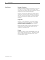
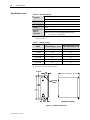
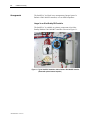
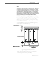
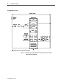
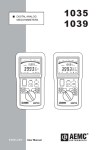
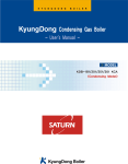
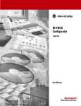
IntelliVAC™ Contactor Control Module Bulletin 1503VC User Manual Important User Information Read this document and the documents listed in the Additional Resources section about installation, configuration, and operation of this equipment before you install, configure, operate, or maintain this product. Users are required to familiarize themselves with installation and wiring instructions in addition to requirements of all applicable codes, laws, and standards. Activities including installation, adjustments, putting into service, use, assembly, disassembly, and maintenance are required to be carried out by suitably trained personnel in accordance with applicable code of practice. If this equipment is used in a manner not specified by the manufacturer, the protection provided by the equipment may be impaired. In no event will Rockwell Automation, Inc. be responsible or liable for indirect or consequential damages resulting from the use or application of this equipment. The examples and diagrams in this manual are included solely for illustrative purposes. Because of the many variables and requirements associated with any particular installation, Rockwell Automation, Inc. cannot assume responsibility or liability for actual use based on the examples and diagrams. No patent liability is assumed by Rockwell Automation, Inc. with respect to use of information, circuits, equipment, or software described in this manual. Reproduction of the contents of this manual, in whole or in part, without written permission of Rockwell Automation, Inc., is prohibited. Throughout this manual, when necessary, we use notes to make you aware of safety considerations. WARNING: Identifies information about practices or circumstances that can cause an explosion in a hazardous environment, which may lead to personal injury or death, property damage, or economic loss. ATTENTION: Identifies information about practices or circumstances that can lead to personal injury or death, property damage, or economic loss. Attentions help you identify a hazard, avoid a hazard, and recognize the consequence. IMPORTANT Identifies information that is critical for successful application and understanding of the product. Labels may also be on or inside the equipment to provide specific precautions. SHOCK HAZARD: Labels may be on or inside the equipment, for example, a drive or motor, to alert people that dangerous voltage may be present. BURN HAZARD: Labels may be on or inside the equipment, for example, a drive or motor, to alert people that surfaces may reach dangerous temperatures. ARC FLASH HAZARD: Labels may be on or inside the equipment, for example, a motor control center, to alert people to potential Arc Flash. Arc Flash will cause severe injury or death. Wear proper Personal Protective Equipment (PPE). Follow ALL Regulatory requirements for safe work practices and for Personal Protective Equipment (PPE). Allen-Bradley, Rockwell Software, Rockwell Automation, and TechConnect are trademarks of Rockwell Automation, Inc. Trademarks not belonging to Rockwell Automation are property of their respective companies. Table of Contents Product Description Chapter 1 Introduction ..............................................................................1-1 Description ...............................................................................1-1 IntelliVAC Features ......................................................... 1-2 IntelliVAC Versions ......................................................... 1-3 Specifications .......................................................................... 1-4 Mounting and Connections .............................................. 1-4 Configuration ................................................................... 1-4 Firmware .......................................................................... 1-4 Electrical Ratings (Table 1.A) .......................................... 1-5 Mechanical Ratings (Table 1.B) ....................................... 1-6 Altitude Derating (Table 1.C) .......................................... 1-6 Receiving and Storage Chapter 2 Receiving ............................................................................... 2-1 Storage .................................................................................... 2-1 Installation and Wiring Chapter 3 General Precautions ................................................................ 3-1 Safety and Codes .................................................................... 3-1 Arrangements .......................................................................... 3-2 Integral to an Allen-Bradley MV Controller .................... 3-2 OEM ................................................................................. 3-3 Fuse Protection ....................................................................... 3-6 Grounding ............................................................................... 3-6 Connections ............................................................................ 3-7 Control Power .................................................................. 3-7 Status Relays .................................................................... 3-7 Interface Connections ....................................................... 3-8 Wiring Guidelines Electrically Held Contactors .................. 3-10 Two-Wire Control .......................................................... 3-11 Three-Wire Control ........................................................ 3-12 Wiring Guidelines Mechanically Latched Contactors .......... 3-14 Mechanically Latched Contactors ........................................ 3-15 Capacitor Trip ................................................................ 3-14 Motor Jogging Control ......................................................... 3-17 Time Delay Undervoltage ..................................................... 3-18 1503-UM051D-EN-P – June 2013 ii Table of Contents Setup and Commissioning Chapter 4 IntelliVAC Configuration ....................................................... 4-1 Monitoring & Troubleshooting Chapter 5 Introduction ............................................................................. Module Status ......................................................................... Contactor Status ...................................................................... Series B Design ................................................................ Spare Parts 5-1 5-1 5-2 5-2 Chapter 6 Spare Parts List ....................................................................... 6-1 Optional Equipment ......................................................... 6-1 Appendix A Typical Contactor Drop-out Times Table A.1 – Contactor Drop-out Times ................................. A-1 1503-UM051D-EN-P – June 2013 Chapter 1 Product Description Introduction This document contains information for the Allen-Bradley Bulletin 1503VC IntelliVAC™ control module. The Bulletin 1503VC is used to control the Allen-Bradley Bulletin 1502 vacuum contactors that are a significant component of the Bulletin 1500/1900 Centerline Medium Voltage Motor Controllers offered by Rockwell Automation. An IntelliVAC control module may also be provided as a loose component, for application with a Bulletin 1502 contactor by a third party (OEM). Description IntelliVAC is an efficient and flexible solution for controlling medium voltage vacuum contactors used in motor starter and feeder applications. IntelliVAC may be used to control both 400 and 800 Amp contactors. Electrically held and mechanically latched contactor types can be controlled with IntelliVAC. Figure 1.1 – IntelliVAC Contactor Control Module 1503-UM051D-EN-P – June 2013 1-2 Product Description Description (cont.) External Capacitor (Optional) Coil Power Supply Current Regulator Control Power Supply C C IGBT Coil Switching Close Signal Contactor Coil(s) Interface Coil Current Transducer Input Power Conditioning Supply Voltage 110-240 VAC or 110-250 VDC Vacuum Contactor Trip Coil Command Inputs Open Signal Vacuum Contactor Auxiliary Micro Controller CC Aux. Feedback c c Altitude Select Vacuum Contactor Close Coil Drop-Out Select c c c c c c c Status Outputs c c TDUV Time Select Module Status Configuration Inputs (DIP switches) Contactor Select Flash EEPROM Interface c c c c Power Up Safety Contactor Status Figure 1.2 – IntelliVAC Block Diagram IntelliVAC Features 1503-UM051D-EN-P – June 2013 A wide range of supply voltage (110 – 240 V AC 50/60 Hz, 110 - 250 V DC) allows implementation in multiple applications Consistent vacuum contactor pick-up time (at a given supply voltage) ensures repeatable performance Selectable vacuum contactor drop-out time improves coordination with upstream power fuses Electronic altitude compensation (400 A only) eliminates mechanical compensation required for altitudes above 1,000 meters (800 A contactors include a user-friendly altitude adjustment) Power loss ride-through (TDUV) allows the vacuum contactor to remain closed during short power loss (may require an optional external capacitor, dependant on ride-through time) Product Description 1-3 IntelliVAC Features (cont.) Anti-kiss and anti-pumping protection ensure that the vacuum contactor close – open sequence occurs as expected, avoiding rapid re-closure due to faulty control devices Delayed restart protects the vacuum contactor by ensuring that the rated duty cycle is not exceeded Temporary jog function (electrically held contactors only) allows the motor to be positioned for process set-up IntelliVAC Versions Series A There are two versions of IntelliVAC control. The first type is used to control vacuum contactors that are electrically held, with a single electrical coil that is economized electronically. The second is used to control mechanically latched vacuum contactors. Series B There is a single version of IntelliVAC, to control both electrically held and mechanically latched vacuum contactors. Refer to Chapter 6, for catalog numbers for each version of IntelliVAC. A Series B IntelliVAC module can be used to replace a Series A module. 1503-UM051D-EN-P – June 2013 1-4 Product Description Specifications Mounting & Connections The IntelliVAC control modules are mounted using two (2) screws (see Figure 1.3). They are typically located in the low voltage control panel of the medium voltage controller (Bulletin 1500/1900 controllers, in the case of Rockwell Automation). IntelliVAC is interfaced to the Bulletin 1502 vacuum contactors using a “quick” connector, located at the module, a wire harness and “quick” connector at the contactor. Control power and other control circuit connections are similarly achieved with “quick” connectors. Configuration IntelliVAC is easily configured for a wide variety of medium voltage motor and feeder control applications. It is configured using DIP switches, located within the enclosure (front side). Please refer to Chapter 4 for information. Bulletin 1500/1900 controllers are shipped with IntelliVAC preconfigured for the required application. Please refer to the documents provided with the order. Firmware IntelliVAC has firmware stored in flash EEPROM; therefore, this may be updated in the field (if necessary). The IntelliVAC board firmware is updated using the mini-DIN connector, which is accessible inside the enclosure. 1503-UM051D-EN-P – June 2013 Product Description 1-5 Table 1.A – Electrical Ratings Main Input Voltage (L1 to L2/N) AC – 110 to 240 V rms, +10/-15%, 47 to 63 Hz DC – 110 to 250 V, +10/-15% Description Main Input Current (L1 to L2/N) Contactor Ratings Control Voltage (Amps) (AC or DC) 400/800 120/240 25 A peak (1/2 cycle) 25 A peak Idle Current (Maximum without contactor coil energized) 400/800 120/240 125 mA 35 mA Hold Current (maximum) 400/800 120/240 300 mA 100 mA 120 4.6 A 3.6 A 240 3.4 A 3.3 A 120 11.3 A 4.8 A 240 8.9 A 4.5 A 120 7.0 A 3.7 A 240 3.6 A 2.0 A 120 7.0 A 3.3 A 240 4.3 A 1.9 A Close Current Trip Current (latch) 400 800 400 (0.2 sec) 800 Command Inputs \ AC – 100 to 240 V rms DC – 24 to 250 V Maximum on state current for open or close command: 9mAAC @ 250 V AC, 60Hz, TA=60°C 9mADC @ 250 V DC, TA=60°C Minimum on state current for open or close command: 2mAAC @ 100 V AC, 60Hz, TA=60°C 600µADC @ 24 V DC, TA=60°C Maximum off state current for open or close command: 400µAAC @ 11 V AC, 60Hz, TA=60°C 400µADC @ 15 V DC, TA=60°C Status Output Contacts AC – 250 V rms, 5 A, R load; 2 A (reactive), PF=0.4 DC – 30 V, 5 A, R load; 2 A (reactive), L/R=7 ms Standards and Approvals CE , cULus, CSA, IEC pending \ DC Rating Inrush Current (0.2 sec) AC Rating TA = Ambient Temperature Refer to Chapter 6 for suitable EMC filter needed to meet CE requirements. Also refer to Chapter 3 for EMC filter installation guidelines. Please consult Factory for DC input current ratings. Includes idle current. Ensure compatibility of IntelliVAC input ratings with those of circuit components activating these inputs. Consider means of isolating/loading these signals, as required (using interposing relays or load resistors.) Consult factory for assistance, if needed. 1503-UM051D-EN-P – June 2013 1-6 Product Description Specifications (cont.) Table 1.B – Mechanical Ratings Temperature Operating: 0° to 60°C ambient at the control module X Non-Operating: -40° to 85°C Altitude -1000 to 5000 meters Pollution Pollution level II (as defined by UL 840 and IEC 60664-1) Humidity Class II Shock and Vibration (Operational) X Shock – 15 g peak, 11 milliseconds Vibration – 10 to 57 Hz, 0.015 inch displacement peak to peak - 57 to 150 Hz, 2.5 g acceleration Ambient temperature is derated at altitudes above 1,000 meters (3,300 feet). Please refer to Table 1.C. Table 1.C – Altitude Derating X Y Altitude DIP Switch Setting 1, 2, 3 X Maximum Operating Ambient at the control module (°C) Y -1000 to 0 000 60 1 to 1000 001 60 1001 to 2000 010 58 2001 to 3000 011 56 3001 to 4000 100 54 4001 to 5000 101 52 Refer to Chapter 4. Derate by 2°C / 1000 m for high altitude operation 5.1 (0.20) 29.7 (1.17) 165.9 (6.53) 5.8 (0.228) 2 places 174.8 (6.88) 185.3 (7.29) 59.4 (2.34) Dimensions in mm (inches) Figure 1.3 – Mechanical Dimensions 1503-UM051D-EN-P – June 2013 Chapter 2 Receiving and Storage Receiving Upon receiving the controller, remove the packing and check for damage that may have occurred during shipping. Report any damage immediately to the claims office of the carrier. NOTE: If the IntelliVAC module is an integral component of a complete MV controller (Bulletin 1500/1900), special receiving and handling instructions will apply. For details, refer to the service manual provided with the equipment. Storage It is important to consider the following storage requirements if you are not installing your controller immediately after receiving it. • Store the controller in a clean, dry, dust-free environment. • Storage temperature should be maintained between -40°C and 85°C (-40°F and 185°F). • Relative humidity must not exceed 95%, non-condensing. 1503-UM051D-EN-P – June 2013 2-2 Receiving and Storage (This page is intentionally left blank.) 1503-UM051D-EN-P – June 2013 Chapter 3 Installation and Wiring General Precautions In addition to the precautions listed throughout this manual, the following statements, which are general to the system, must be read and understood. ATTENTION ATTENTION ATTENTION Safety and Codes ATTENTION The controller contains ESD (electrostatic discharge) sensitive parts and assemblies. Static control precautions are required when installing testing, servicing, or repairing the assembly. Component damage may result if ESD control procedures are not followed. If you are not familiar with static control procedures, refer to applicable ESD protection handbooks. An incorrectly applied or installed controller can damage components or reduce product life. Wiring or application errors, such as incorrect or inadequate AC supply, or excessive ambient temperatures, may result in malfunction of the system. Only personnel familiar with the controller and associated machinery should plan or implement the installation, start-up, and subsequent maintenance of the system. Failure to do this may result in personal injury and/or equipment damage. The Canadian Electrical Code (CEC), National Electrical Code (NEC), or other local codes outline provisions for safely installing electrical equipment. Installation MUST comply with specifications regarding wire type, conductor sizes, branch circuit protection, interlocking and disconnect devices. Failure to do so may result in personal injury and/or equipment damage. 1503-UM051D-EN-P – June 2013 3-2 Installation and Wiring Arrangements The IntelliVAC is offered in two arrangements, Integral (part of a Bulletin 1500/1900 MV controller) or as an OEM component. Integral to an Allen-Bradley MV Controller The IntelliVAC is available as a primary component of an AllenBradley Bulletin 1500/1900 MV controller as shown in Figure 3.1. Figure 3.1 - Typical IntelliVAC Installation within a Bulletin 1500/1900 MV Controller (Shown with optional external capacitor) 1503-UM051D-EN-P – June 2013 Installation and Wiring 3-3 OEM The IntelliVAC may be ordered as an OEM component. This allows the OEM to mount the components in a configuration most suitable to the motor controller equipment layout. Care must be exercised to ensure the IntelliVAC has adequate ventilation provided around it. Refer to Figure 3.2 for mounting the IntelliVAC. It is recommended that a minimum of 1.5 inches (38.1mm) of free air space be provided between the IntelliVAC and any solid barrier above or below. The OEM is responsible for controller fusing, motor overload protection, control devices (eg. Start/Stop push buttons), and wiring between the IntelliVAC and 1502 vacuum contactor (using optional wire harness). Wiring and mounting for optional items, such as TDUV Capacitor are also the OEM’s responsibility. Refer to Figure 3.3 or 3.4 for basic connections. An optional EMI filter is required to meet CE EMC requirements (refer to Chapter 6 for recommended type). Minimum top clearance 38.1 (1.50) Dimensions in mm (inches) 38.1 (1.50) Minimum bottom clearance 6.4 (0.25) Additional Modules (as required) Figure 3.2 – Typical Mounting Configurations Note: Adjacent IntelliVAC modules may be mounted with a minimum separation of 6.4 mm (0.25 inches). 1503-UM051D-EN-P – June 2013 3-4 Installation and Wiring Arrangements (cont.) CONTROL POWER * M-INTELLIVAC CONTROL POWER FUSE 7 + 9 + OVERLOAD STOP - 8 OPEN CLOSE START 16 - 10 CONTACTOR STATUS 15 14 MODULE STATUS CAPACITOR (OPTIONAL) M 13 1 EC 2 + TCO 4 3 11 AUX 12 CCO 6 5 MOV M CONFIGURATION DIP SWITCHES L1 ∗ INPUT POWER G L2/N Refer to Table 3.A for recommended fuse sizing. Figure 3.3 – IntelliVAC Typical Schematic (Electrically Held Vacuum Contactor) Without Optional EMC Filter 1503-UM051D-EN-P – June 2013 Installation and Wiring 3-5 CONTROL POWER M-INTELLIVAC * CONTROL POWER FUSE 7 + 9 + OVERLOAD STOP - 8 OPEN - 10 CLOSE START 16 CONTACTOR STATUS 15 14 MODULE STATUS CAPACITOR (OPTIONAL) M 13 1 EC 2 + TCO 4 3 11 AUX 12 CCO 6 5 MOV M CONFIGURATION DIP SWITCHES L1 P' P ∗ INPUT POWER G L2/N EMC FILTER G N' N Refer to Table 3.A for recommended fuse sizing. Figure 3.4 – IntelliVAC Typical Schematic (Electrically Held Vacuum Contactor) With Optional EMC Filter 1503-UM051D-EN-P – June 2013 3-6 Installation and Wiring Fuse Protection The IntelliVAC module requires external fuse protection to coordinate with the power supply and contactor. The fuse ratings shown in Table 3.A allow the passage of inrush currents expected when the contactor is closed, or from recommended external capacitors for the TDUV option. They will also protect the contactor coils in the event of a module malfunction. The recommended fuses have been tested to ensure reliable protection of the module. If the supply voltage is DC, the module must be used with an external fuse that is approved for and rated to interrupt the DC voltage supply. The types listed are Ferraz-Shawmut Midget Fuses (1-1/2" X 13/32"). The TRM is a time-delay type, rated 250 VAC. The ATM is a fast-acting type, rated 500 VDC. Table 3.A – IntelliVAC Fuse Protection Rated Supply Voltage 110/120 VAC 220/240 VAC 125 VDC 250 VDC Contactor Type 400A EH 800A EH 400/800A ML 400A EH 800A EH 400/800A ML 400A EH/ML 800A EH/ML 400A EH/ML 800A EH/ML Recommended Fuse (minimum) TRM 2 TRM 2 TRM 2 TRM 2 TRM 2 TRM 2 ATM 3 ATM 5 ATM 3 ATM 5 (maximum) TRM 3.2 TRM 6.25 TRM 3.2 TRM 6.25 TRM 6.25 TRM 6.25 ATM 3 ATM 6 ATM 5 ATM 6 EH = Electrically Held vacuum contactor ML = Mechanically Latched vacuum contactor Grounding The IntelliVAC module must be connected to a common ground terminal (PE) on the controller panel. The ground terminal is located on top of the module enclosure for Series A design (refer to Figure 3.7), and on the bottom of module enclosure for Series B design, (refer to Figure 3.6) ATTENTION 1503-UM051D-EN-P – June 2013 It is important that IntelliVAC is properly grounded using the ground connection provided. Failure to do so may result in damage to equipment or personal injury. Installation and Wiring Connections 3-7 There are three green connectors on the IntelliVAC module for connections to the control circuitry. Connector plugs are provided with the module. If additional plugs are required, refer to Chapter 6, Spare parts. Control Power The IntelliVAC can accept either AC or DC control power. Refer to Table 1.A for acceptable input power and control signal ratings. Control power is applied to the module with a two-pole connector located at the bottom rear portion of the module. Refer to Figures 3.5 and 3.6 for connections. The ‘L1’ connection is intended to be the ‘Hot’ or ‘+’ side of the control power, and the ‘L2/N’ connection is intended to be the ‘Neutral’, ‘Return’, or ‘-’ side of the control power. In order to meet CE electromagnetic interference requirements, an external EMC filter must be installed. Refer to Chapter 6 for suitable EMC filter part number and install per Figure 3.4. Status Relays Status relay connections are accessed with a four-pole connector located at the bottom front portion of the module. Refer to Figure 3.5 or 3.6 for connections. There are two status relays, each with one normally-open contact: Module Status: Contactor Status: Terminals 13 and 14 Terminals 15 and 16 Refer to Chapter 5 Monitoring and Troubleshooting for a description of operation for the relays. Refer to Table 1.A for electrical ratings of the status relays. 13 14 15 16 CONTACTOR STATUS OUTPUT (N.O.) L1 L2/N MODULE STATUS OUTPUT (N.O.) POWER INPUT Figure 3.5 – Bottom side connections (Series A) 1503-UM051D-EN-P – June 2013 3-8 Installation and Wiring Connections (cont.) Interface Connections Ground Connection 13 14 15 16 L1 L2/N CONTACTOR STATUS OUTPUT (N.O.) MODULE STATUS OUTPUT (N.O.) POWER INPUT Figure 3.6 – Bottom side connections (Series B) Interface Connections All other control interface connections are made at a twelve-pole connector located on the top of the module. Refer to Figure 3.7 or 3.8 and Table 3.B for connections. Refer to the Wiring Guidelines section in this chapter for guidance in making connections to the control circuit. 1 2 3 4 5 6 7 8 9 10 11 12 EX. CAP. CONTACTOR INTERFACE Ground Connection Figure 3.7 – Top side connections (Series A) 1 2 3 4 5 6 7 8 9 10 11 12 EX. CAP. CONTACTOR INTERFACE Figure 3.8 – Top side connections (Series B) 1503-UM051D-EN-P – June 2013 Installation and Wiring 3-9 Table 3.B – Terminal Assignments for IntelliVAC Interface Connections X Terminal No. X Y Z Terminal Designation 1 External capacitor (negative) Y 2 External capacitor (positive) Y 3 Latch trip coil (common) Y 4 Latch trip coil Y 5 Close coil (common) 6 Close coil 7 Open / Jog command Y Z 8 Open / Jog command (common) Y Z 9 Close command Z 10 Close command (common) Z 11 Contactor auxiliary contact Z 12 Contactor auxiliary contact Z Description Power connection for TDUV or capacitor trip options only Output for mechanical latch contactor trip coil Output to close coil of electrically held & mechanical latch contactors Input to open a mechanical latch contactor or jog an electrically held contactor (mutually exclusive) Input to initiate the closure of electrically held & mechanical latch contactors Input to indicate the state of the contactor (typically wired to a normally closed auxiliary contact) Refer to Table 1.A for electrical ratings. No connection required if option is not used. Ensure compatibility of IntelliVAC input ratings with those of circuit components activating these inputs. Consider means of isolating/loading these signals, as required (using interposing relays or load resistors). Consult factory for assistance, if needed. 1503-UM051D-EN-P – June 2013 3-10 Installation and Wiring Wiring Guidelines Electrically Held Contactors The IntelliVAC can be applied with two- or three-wire control circuits. The control system utilized will determine the configuration of the input wiring. Consider the following input and output for the type of control used: • Terminals 9 and 10 • Terminals 15 and 16 Close Contactor Contactor Status In either case, the CLOSE input must receive a maintained voltage high to keep the contactor closed. Note: 1. When used with electrically held contactors, the IntelliVAC allows close commands every six seconds. This is to ensure the rated contactor duty cycle is not exceeded. 2. If a contactor close command is applied and then removed in less than 500 milliseconds the IntelliVAC may fault. To clear the fault, module power has to be removed and reapplied. 3. If IntelliVAC powers up configured for an electrically held contactor, and the vacuum contactor is detected as being closed, the module will not respond to a close command until the vacuum contactor auxiliary contact input is in the correct (open) state and module power is removed and re-applied. (See Chapter 5). This is true if the power-up safety DIP switch is enabled. 4. In general, a Close command should only be applied 4 seconds after energizing IntelliVAC. 1503-UM051D-EN-P – June 2013 Installation and Wiring 3-11 Two-Wire Control If using two-wire control, the CLOSE contactor input is maintained high using a single contact. Momentarily opening this input will cause the IntelliVAC to open the contactor. Maintaining the contact will provide a CLOSE command to IntelliVAC (given that all permissives are satisfied). If a fault occurs, in addition to cycling control power to the IntelliVAC module, the CLOSE command must be removed for a minimum of 4 seconds, before being re-applied. Refer to Figure 3.9. Some two-wire control schemes may be configured such that a close command is present when IntelliVAC is energized. In this case, the Power-Up Safety feature may be disabled by setting DIP switch 12 accordingly. (Available with an IntelliVAC using firmware 2.001 (or newer) refer to Table 4.B). Note: Only disable the Power-Up safety feature when absolutely necessary. Doing so can create unsafe operating conditions. CONTROL POWER CAPACITOR (OPTIONAL) * CONTROL POWER FUSE M 1 EC 2 + 11 AUX 12 L1 P' P TCO 4 3 CCO 6 5 G EMC FILTER G MOV M L2/N N' N RUN OVERLOAD ∗ M-IV Refer to Table 3.A for recommended fuse sizing. M-IV 9 + - 10 CLOSE Figure 3.9 – Two-Wire Control 1503-UM051D-EN-P – June 2013 3-12 Installation and Wiring Wiring Guidelines Electrically Held Contactors (cont.) Three-Wire Control If using three-wire control, the CLOSE contactor input is maintained high using two contacts. Momentarily opening this input will cause the IntelliVAC to open the contactor. Momentarily closing the START contact will provide a CLOSE command to IntelliVAC (given that all permissives are satisfied). In this configuration, the STATUS output acts as a seal-in contact. If a fault occurs, in addition to cycling control power over to the IntelliVAC module, the CLOSE command must be removed for a minimum of 4 seconds before being re-applied. Refer to Figure 3.10. CONTROL POWER CAPACITOR (OPTIONAL) * CONTROL POWER FUSE 1 EC 2 + M 11 AUX 12 L1 P' P OVERLOAD M-IV STOP TCO 4 3 CCO 6 5 G MOV M L2/N EMC FILTER G N' N START 9 + - 10 M-IV ∗ Refer to Table 3.A for recommended fuse sizing. 15 CLOSE 16 CONTACTOR STATUS Figure 3.10 – Three-Wire Control 1503-UM051D-EN-P – June 2013 M-IV Installation and Wiring 3-13 15mS CLOSE COMMAND TO MICRO DEBOUNCE 80mS 15mS DEBOUNCE Y 5mS CLAMP DELAY MICRO OUTPUT TO CLOSE COIL 200mS CLOSE LEVEL OF CURRENT TO CLOSE COIL CONTACTOR STATUS RELAY OUTPUT SELECTABLE DROP OUT TIME (0 TO 190mS) 60mS ACKNOWLEDGE WINDOW X MODULE STATUS RELAY OUTPUT CONTACTOR PICK UP 90mS (@120VAC) NATURAL CONTACTOR DROP OUT 30mS CONTACTOR AUXLIARY INPUT TO MICRO X Contact status relay closes on request to close. It will open if the contactor auxiliary contact does not close within 200 milliseconds and module will fault (opening module status relay). Y For this example, the 130 millisecond drop-out time has been selected. The base drop-out time is 50 milliseconds. The microcontroller delay is 130-50=80 milliseconds. Figure 3.11 – Timing Diagram 400A (Electrically Held) Contactor with IntelliVAC Control for three-wire Control 1503-UM051D-EN-P – June 2013 3-14 Installation and Wiring Wiring Guidelines Mechanically Latched Contactors IntelliVAC control may be used for mechanically latched contactors. A momentary control signal is needed to close the contactor, and a second momentary control signal is needed to open the contactor. The momentary open/close commands must be at least 50 milliseconds in duration. Refer to Figure 3.12 for a typical mechanical latch control scheme. Note: 1. A mechanically latched contactor may already be closed when power is applied to the IntelliVAC control module. 2. It is permissible to apply an open command to the IntelliVAC module as power is re-applied. CONTROL POWER M * 1 EC 2 + CONTROL POWER FUSE M M-IV TCO 4 3 MOV TC MOV 11 AUX 12 L1 P' P CCO G EMC FILTER G CLOSE 6 5 CC L2/N N' N M-IV 9 + - 10 CLOSE OPEN OVERLOAD ∗ M-IV 7 + OPEN Refer to Table 3.A for recommended fuse sizing. Figure 3.12 – Mechanically Latched Contactor Control 1503-UM051D-EN-P – June 2013 8 Installation and Wiring Mechanically Latched Contactors 3-15 Capacitor Trip The IntelliVAC can be configured to provide capacitor trip functionality with mechanically latched contactors. A capacitor must be connected to the IntelliVAC (terminals #1 and #2) in order to provide this capability. The capacitor provides control power for the IntelliVAC as well as stored energy to trip the contactor. Maximum recommended capacitor size is 1650 µF for 120V control or 330 µF for 240V control. Use of larger capacitors will require a current limiting circuit to prevent opening the control fuse on energization. The IntelliVAC must receive an ‘OPEN’ command within a few seconds of losing AC control power. This time limit depends on voltage and capacitor size as shown in the table below. If the elapsed time exceeds this limit, the contactor cannot be tripped by IntelliVAC. A separate voltage source is needed to provide the ‘OPEN’ command. This may be taken from the external capacitor as shown in Figure 3.13. Table 3.C – Mechanically Latched Contactor – Capacitor Trip Times Contactor Rating Nominal Voltage (Vac) Actual Vinput (Vac) Ext. Capacitor (µF) 120 120 400 Amp 3.5 1650 100 240 Note: 110 240 200 Max. time for trip (sec) 2.7 1.7 330 7.5 4.7 Minimum capacitor voltage ratings • 120V applications – 200V DC (250V DC preferred) • 240V applications – 400V DC (450V DC preferred) 1503-UM051D-EN-P – June 2013 3-16 Installation and Wiring CONTROL POWER M-IV OPEN * CONTROL POWER FUSE OVERLOAD 7 + - 8 OPEN M CAPACITOR M 1 EC 2 + TCO 4 3 MOV TC MOV 11 AUX 12 L1 P' P CLOSE M-IV CCO G EMC FILTER G 6 5 CC L2/N N' N M-IV 9 + - 10 ∗ Refer to Table 3.A for recommended fuse sizing. CLOSE Figure 3.13 – Mechanically Latched Contactor with Capacitor Trip Option 1503-UM051D-EN-P – June 2013 Installation and Wiring Motor Jogging Control 3-17 When used with electrically held contactors, the IntelliVAC allows close commands every six seconds. This is to ensure the rated contactor duty cycle of 600 operations per hour is not exceeded. For motor jogging operations, the second control input, or OPEN command, will close the contactor for as long as the input is present, and open the contactor when the input is removed. (Refer to Figure 3.14.) This method will bypass the standard six second motor restart delay for jogging purposes only. CONTROL POWER * CONTROL POWER FUSE 1 EC 2 + M 11 AUX 12 L1 P' P OVERLOAD M-IV STOP TCO 4 3 CCO 6 5 G MOV M L2/N EMC FILTER G N' N START 9 + - 10 M-IV 15 CLOSE 16 CONTACTOR STATUS JOG M-IV M-IV 7 + - * Refer to Table 3.A for recommended fuse sizing. 8 OPEN Figure 3.14 – Motor Jogging Control 1503-UM051D-EN-P – June 2013 3-18 Installation and Wiring Time Delay Undervoltage The IntelliVAC can be configured to provide time delay undervoltage (TDUV) protection. The feature is available to keep electrically held contactors closed during a voltage dip or brief power loss. This option may require the addition of a capacitor (see below). Refer to Chapter 6 for typical capacitor sizing. The capacitor is connected to terminals 1(-) and 2(+) of the IntelliVAC. (Refer to Figure 3.15.) Table 4.B of the “Setup and Commissioning” chapter has the dip switch settings to provide TDUV from 0.2 to 2 seconds. IntelliVAC can provide TDUV protection without the use of an external capacitor, as shown in Table 3.D. Table 3.D – Maximum TDUV Time (without Capacitor) Control Voltage Max. TDUV Time (secs) 110/120 V 220/240 V 0.2 1.0 The following conditions will initiate TDUV protection, regardless of the supply voltage: 1. If the supply voltage drops below 90 VAC/VDC after the first 200 milliseconds after a contact close request. 2. When the supply voltage drops below 72 VAC/FDC after the 200 millisecond close sequence. If the undervoltage condition persists beyond the set delay time, the contactor will be opened and an undervoltage fault condition will occur. CONTROL POWER CAPACITOR * CONTROL POWER FUSE M 1 EC 2 + 11 AUX 12 L1 P' P OVERLOAD M-IV TCO 4 3 CCO 6 5 G MOV M L2/N EMC FILTER G N' N START STOP 9 + - 10 M-IV ∗ Refer to Table 3.A for recommended fuse sizing. 15 M-IV CLOSE 16 CONTACTOR STATUS Figure 3.15 – TDUV Control Circuit 1503-UM051D-EN-P – June 2013 Chapter 4 Setup and Commissioning IntelliVAC Configuration The IntelliVAC module is configured for a specific application by setting DIP switches. They are accessed by loosening the two screws on the front of the unit, and removing the cover by sliding it forward. The switches are found on the front edge of the IntelliVAC circuit board (see Figure 4-1). There are 12 switches, with number 1 being at the top next to the mini DIN connector. (Refer to Table 4.B). Remove power from the module before removing the cover and before changing the DIP switch settings. The new settings are recognized only on power-up. IMPORTANT Ground Stud (Series A) Interface Connections EEPROM Programming Port (Mini DIN Connector) DIP Switches Ground Stud (Series B) Status Relay Outputs Supply Power Input Internal Control Fuse Figure 4.1 – DIP Switch and Connector Locations An IntelliVAC unit shipped separately from the factory will have a default configuration per Table 4.A. Table 4.A – DIP Factory Default Settings Description Altitude: 0 – 1000m Drop-out time: 130 msec Contactor config.: 400A EH TDUV config.: No TDUV Ext. cap TDUV time: 0.2 sec *Power-Up Safety: Enable 1 0 2 0 3 1 4 5 0 1 DIP switch 6 7 8 9 10 11 0 0 12 1 0 1 0 0 1503-UM051D-EN-P – June 2013 Setup and Commissioning 4-2 IntelliVAC units shipped in a complete MV controller (Bulletin 1500/1900) will be configured to suit the installed application (i.e. contactor type). The user should verify the settings before energizing the equipment. Table 4.B defines the settings for each switch. IntelliVAC Configuration (cont.) UP = 1 DOWN = 0 DIP switch SW1 1 2 3 6 7 8 9 10 11 12 | | | | 1 2 3 12 Power-Up Safety Y -1000 to 0 0 0 0 0 Enable 1 to 1000 0 0 1 1 Disable 1001 to 2000 0 1 0 2001 to 3000 0 1 1 10 11 Ext. cap. TDUV time 3001 to 4000 1 1 1 1 0 0 1 1 0 1 0 1 0 0 1 1 0 1 0 1 0.2 sec Not defined Not defined 9 TDUV config. 0 No TDUV 1 TDUV Enabled Drop out time Z 4 5 6 50 msec 0 0 0 75 msec 0 0 1 7 8 Contactor Config. 100 msec 0 0 1 1 1 1 0 0 0 1 0 1 0 0 1 1 0 1 0 1 400A Mech. Latch 1 1 1 1 0 1 130 msec 150 msec 175 msec 200 msec 240 msec Y Z 5 Altitude X 4001 to 5000 X 4 0.5 sec 1.0 sec 2.0 sec 400A Elec. Held 800A Mech. Latch 800A Elec. Held The altitude compensation by DIP switch settings applies to Series E 400 amp vacuum contactors only. All 800 amp contactors are adapted for altitude by altering the return springs. 800 amp contactors are to be set for 1 to 1000m (001 DIP setting). Available with IntelliVAC using version 2.001 firmware or newer. By-pass contactors in MV SMC applications must be set for 50 millisecond drop-out time. Refer to Appendix A for typical drop-out time settings used when power fuses are provided by Rockwell Automation. 1503-UM051D-EN-P – June 2013 Chapter 5 Monitoring and Troubleshooting Introduction The IntelliVAC module has two light emitting diodes (LEDs) and relay outputs to indicate the status of the contactor and the module. The LEDs are visible on the front of the module and the relay outputs are accessed on the bottom front of the module. Figure 5.1 – IntelliVAC LEDs Module Status The Module Status is indicated with a Green LED if the module is functioning properly and has a valid configuration. If the module powers up with an invalid configuration the LED will be Red, indicating a Fault condition which will not allow the contactor to close. If the module powers up properly and experiences an undervoltage condition when attempting to close the contactor or while the contactor is closed, the LED will be Red (Fault). If the contactor does not close properly, a Fault is generated, the LED turns Red, and inputs are inhibited until the module power is removed and reapplied. If the processor has an internal fault, the LED will be Red, the outputs will be cleared, and the processor will be reset. If the reset is successful, the LED will be Green and the module will respond to the control inputs. The input command must be toggled before the module will respond to a new command (rising edge triggered). Module Status output relay has a normally open contact. The contact is open during a Fault condition (LED red), and closed during a healthy condition (LED green). The module states for Series A are summarized in Table 5.A. Series B Design Additional module states are indicated with the LED as per Table 5.B. 1503-UM051D-EN-P – June 2013 5-2 Monitoring and Troubleshooting Contactor Status The Contactor Status is indicated with a yellow LED that is off until a CLOSE command is received. The LED will stay on if the contactor closes properly, until the contactor is opened. Contactor Status output relay has a normally open contact. The contact is open when the contactor is open (LED off), and closed when the contactor has received a close command (for 200 milliseconds) or if it is closed (LED on). Series B Design Additional module states are indicated with the LED as per Table 5.B. Table 5.A – IntelliVAC Status Indication (Series A design) Parameter Conditions • Module Status Y • • • • • • • • Contactor Status • • • • X Y Z [ 1503-UM051D-EN-P – June 2013 rated supply voltage and valid configuration undervoltage or contactor fault or invalid configuration X or internal fault insufficient supply voltage rated supply voltage and close command present [ and contactor closed insufficient supply voltage or close command absent [ or contactor open LED State Relay Contact State Green Closed Red Y Open Off Open Yellow Closed Off Open Applies only to power-up condition. Fault is reset by cycling control power. If a contactor close command is applied and then removed in less than 500 milliseconds, the IntelliVAC may fault and the module status LED will turn red. To clear the fault, module power has to be removed and reapplied. For mechanical latch contactors a close command does not need to be maintained for the contactor to remain closed (resulting in a yellow state for contactor status). Monitoring and Troubleshooting 5-3 Table 5.B – IntelliVAC Status Indication (Series B design) Conditions XY Description Module Status LED Color Contactor Status Relay LED Color Relay Normal Healthy Module and Contactor OPEN Green Closed Off Open Normal Healthy Module and Contactor CLOSED Green Closed Yellow Closed Warning Invalid Command Present ^ Yellow Closed Off Open Warning Mechanical Latch Fail to Trip Yellow Open Yellow Closed Fault Power Up with Contactor CLOSED Red – Flash 2 [ Open Yellow Closed Fault Contactor Fails to Pick Up Green Open Red – Flash 1 Z Open Fault Contactor Drop Out During Hold Green Open Red – Flash 2 [ Open Fault Long Contactor Drop Out Time Green Open Red – Flash 3 Z Open Fault Microcontroller Malfunction Red Open Red Open Fault Power Up with Invalid Dip Switch Configuration Red – Flash 1 Open Off Open Fault Undervoltage with a CLOSE Command Present Red Open Off Open X Y Z [ \ ] ^ Warning = Recoverable Condition – Remove and retry offending signal Fault = Non-recoverable condition – Module power must be removed and re-applied. Flash 1 = 1 Flash Red LED followed by a pause. Flash 2 = 2 Consecutive Red LED flashes followed by a pause. Flash 3 = 3 Consecutive Red LED flashes followed by a pause. EH = Only for Electrically Held Contactor Invalid Command Types: 1. Close, Jog or Trip commands present during power up sequence. 2. Close or Jog command re-applied too quickly (before contactor opening sequence is verified). Allow at least 60 msec, plus drop out delay time, before re-applying these signals. NOTE: Contactor will only respond to a close command re-applications after the re-start delay timer has expired. 3. Close and Trip commands present simultaneously (valid with Mechanical Latch contactors only). 1503-UM051D-EN-P – June 2013 5-4 Monitoring and Troubleshooting Table 5.C – Module Troubleshooting Problem or Trip Indicated Contactor does not energize Indication of the following conditions • Motor Protection activated • Both Status LEDs ‘Off’ Possible Solutions • • • • • • Module Status LED ‘Red’ upon power up (Series A) • Module Status LED ‘Red’ upon power up (Series A) • Module Status ‘Red Flash 1’ upon power up (Series B) • Loose connection in control circuit. • • • • Contactor closes momentarily and will not reclose. • Module status LED ‘Red’ and Contactor Status LED ‘Off’ (Series A) • • • • Module status LED ‘Red’ and Contactor Status LED ‘Off’ (Series A) • Module status LED ‘Green’ and Contactor Status LED ‘Red Flash 1’ (Series B) • Both status LEDs ‘Off’ 1503-UM051D-EN-P – June 2013 • • Investigate and reset Check Control Power Loose connections in control circuit Verify IntelliVAC power input plug is in place and properly seated Verify internal control fuse has not opened (Refer to Figure 4.1 for location) IntelliVAC faulted. Cycle control power to reset. Replace IntelliVAC if unsuccessful. Improper setting of dip switches. Check settings and cycle control power. Verify contactor auxiliary set up. Reference Publication 1502-UM052A-EN-P (400A) or 1502-UM051B-EN-P (800A) – Auxiliary Contact Set-up Procedure. Verify circuit continuity (is contactor plug connected properly?) Coil damaged or connections are loose. Repair and cycle control power. Auxiliary Contact Assembly improperly adjusted. Reference Publication 1502UM052A-EN-P (400A) or 1502-UM051B-EN-P (800A) – Auxiliary Contact Set-up Procedure. Cycle control power to reset. Undervoltage fault (no TDUV), control voltage dipped below trip point. Cycle control power to reset. Verify voltage levels are 110 to 240 VAC, 110 to 250VDC Armature Plate obstructed from closing to coil face. Verify no foreign material behind the armature plate. Cycle control power to reset. Check internal control fuse. Verify IntelliVAC operation in test mode before applying Medium Voltage. (Refer to Fig. 4.1 for location.) Monitoring and Troubleshooting 5-5 Table 5.C – Module Troubleshooting (cont.) Problem or Trip Indicated Contactor opens during operation Indication of the following conditions • Motor Protection activated • Stop command initiated • Module Status LED ‘Red’ Possible Solutions • • • • Contactor does not open (mechanical latch only) • Module Status LED ‘Green’ and Contactor Status LED ‘Red Flash 2’ (Series B only) • • Both status LEDs ‘Off’ • • Module Status LED ‘Red’ and Contactor Status LED ‘Yellow’ (Series A, with firmware 2.001 or newer) • Module Status LED ‘Yellow’ and Contactor Status LED ‘Yellow’ (Series B, with firmware 2.001 or newer) • • • Investigate and reset. Verify circuit Undervoltage fault (no TDUV), control voltage dipped below trip point. Cycle control power to reset. Verify voltage levels are 110 to 240 VAC, 110 to 250 VDC. With external capacitor and TDUV feature activated, undervoltage condition for longer than programmed TDUV time. Undervoltage fault activated. Cycle control power to reset. Contactor Status feedback between Terminals 11 and 12 on the IntelliVAC has closed. The IntelliVAC will de-energize the coil, thinking the contactor has opened for other reasons. Check control voltage and internal control fuse. (Refer to Figure 4.1 for location.) Check control power to ensure that it has not dipped below minimum (see Table 5.D). Trip mechanism is damaged. Inspect and replace if needed. Check for loose connections in the control circuit. Refer to Tables 5.A or 5.B for definition of Module LED states. Table 5.D – Minimum IntelliVAC Operational Supply Voltages Voltage Level Contactor Rating (Amps) Minimum Voltage (VAC, 47 to 63 Hz) Pick-Up 400/800 95 Drop-Out 400/800 75 400 70 800 80 Trip (Mechanical Latch) 1503-UM051D-EN-P – June 2013 5-6 Monitoring and Troubleshooting (This page is intentionally left blank.) 1503-UM051D-EN-P – June 2013 Chapter 6 Spare Parts Spare Parts List IntelliVAC (electrically held) Series A IntelliVAC (mechanical latch) Series A IntelliVAC (electrically held and mechanical latch) Series B 1503VC-BMC1 1503VC-BMC2 Internal Fuse: 6.3 A, 250 V (Littlefuse 21506.3) 80174-902-14-R Multi-pole connectors: 2 pole (module power) 4 pole (status outputs) 12 pole (coil and I/O connections) 80174-014-01-R 80174-014-03-R 80174-014-11-R 1503VC-BMC3 Optional Equipment TDUV Capacitor* For 110/120V AC control (1650 µF) For 220/240V AC control (330 µF) 80158-779-51-R 80158-779-52-R *Includes mounting bracket and terminal guards EMC Filter Schnaffer (FN 670-10/06) 80026-430-01-R 1503-UM051D-EN-P – June 2013 6-2 Spare Parts 1503-UM051D-EN-P – June 2013 Appendix A Typical Contactor Drop-out Times The contactor drop-out times shown in the following table are typical values used when the power fuses are provided as part of a complete MV controller from Rockwell Automation. The recommendations are based on Ferraz Shawmut power fuses. Other fuse types may require alternate drop-out time settings. Table A.1 – Contactor Drop-out Times Fuse Rating Voltage < 5000 < 5000 Contactor Drop-out Time (msec) Current 2R 3R 4R 6R 9R 12R 18R 19R 24R 32R 38R 48X 57X 2 x 24R 2 x 32R 2 x 38R 20E 30E 40E 50E 65E 80E 100E 125E 150E 175E 200E 250E 300E 350E 400E 450E 500E 600E 750E 900E 400A 800A 50 50 100 240 75 200 100 240 240 * 50 50 75 100 130 75 200 240 * Fuse not suitable for use with 400A contactor. 1503-UM051D-EN-P – June 2013 A-2 Typical Contactor Drop-out Times Table A.1 – Contactor Drop-out Times (cont.) Fuse Rating Voltage 7200 8250 Contactor Drop-out Time (msec) Current 2R 3R 4R 6R 9R 12R 18R 24R 2X18R 2X24R 20E 30E 40E 50E 65E 80E 100E 125E 150E 175E 200E 400A 800A 50 50 75 150 130 50 50 Fuse not suitable for use with 400A contactor. Note: The drop-out time is chosen to be equal to or greater than the intersection of the rated contactor interrupting current and the fuse melt time curve (except where noted *) 1503-UM051D-EN-P – June 2013 Medium Voltage Products, 135 Dundas Street, Cambridge, ON, N1R 5X1 Canada, Tel: (1) 519.740.4100, Fax: (1) 519.623.8930, www.ab.com/mvb Publication 1503-UM051D-EN-P – June 2013 Supersedes Publication 1503-UM051C-EN-P – January 2006 Copyright © 2013 Rockwell Automation, Inc. All rights reserved. Printed in Canada.