1
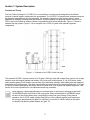
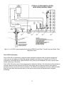
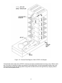
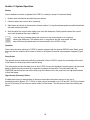
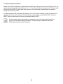
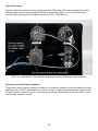
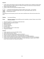
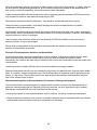
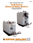
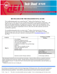
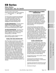
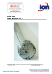
LO-PRO II Low Profile Air Stripper Installation and Operation Manual Rev 01/09/2013 Part # 10352 Table of Contents Section 1: System Description ………………………………….……………………………………….. Section 2: System Installation ……………………………………………………………………………. Section 3: System Operation …………………………………….……………………………………… Section 4: System Maintenance ………………………………….…………………….………….…… Section 5: System Troubleshooting ……………………………….…………………….……………... Section 6: System Specifications ………………….……………….………………….……………….. Section 7: System Schematic …………..…...…………………….……………………………………. Section 8: Replacement Parts and Accessories …………………..…………….……….…………… Appendix A: Decontamination Procedures ……………….…………………………………………… Warranty and Repair ……………………….………………………..…………………………………… 1 3 12 19 21 29 35 38 39 41 44 DOCUMENTATION CONVENTIONS This uses the following conventions to present information: An exclamation point icon indicates a WARNING of a situation or condition that could lead to personal injury or death. You should not proceed until you read and thoroughly understand the WARNING message. WARNING A raised hand icon indicates CAUTION information that relates to a situation or condition that could lead to equipment malfunction or damage. You should not proceed until you read and thoroughly understand the CAUTION message. CAUTION A note icon indicates NOTE information. Notes provide additional or supplementary information about an activity or concept. NOTE 2 Section 1: System Description Function and Theory The Low Profile Air Stripper II (LO-PRO II) is a cost-effective, modular system designed for the efficient removal of volatile organic compounds from groundwater. The LO-PRO II is compact and unobtrusive and can be discreetly integrated into any site landscape. The modular construction of the system makes it easily adaptable to changing conditions and requirements. By simply adding or subtracting aeration trays, the LOPRO II can be fine-tuned for different influent concentrations and removal efficiencies. Figure 1-1 shows a standard five-tray system. Figure 1-2 is an example of a LO-PRO II system with optional equipment components. Figure 1-1 – Example of a LO-PRO II with five trays. The standard LO-PRO II system consists of a 70 gallon (265 liter) sump with integral floor mounts, five to eight aeration trays with integral gaskets and latches, a lid (cover) with mist eliminator, a 3 or 5HP blower, and a static pressure gauge. Each aeration tray consists of an alternating, stainless steel bubble plate with attached downcomer for funneling water. The sump, trays and lid are constructed of low density polyethylene. PVC pipe is used for all external plumbing and fittings. Refer to Section 8 for a list of parts and optional equipment. See Section 4 for more information on unit maintenance and tray orientation. Sump capacity is based approximately on the dimensions of the sump to the height of the water HI OVERRIDE switch (blue float) of the sump probe. When activated the HI OVERRIDE switch will shut off the influent water pump, preventing the sump from over-flowing. During normal operation, the HI LEVEL switch (orange float) will turn on the effluent transfer pump and empty the sump (of approximately 39 gallons or 148 liters) or until the LO LEVEL switch on the probe is reached. See also the probe diagram in Figure 1-5. 3 Figure 1-2 - LO-PRO II system deployed with optional GECM Control Panel, Transfer Pump and Water Table Depression Pump. The LO-PRO II(S) System The LO-PRO IIS is a freestanding, integrated system designed to operate under the rigorous demands of continuous duty air stripping, but requiring minimal installation and field wiring. Operation of LO-PRO IIS components is controlled with an optional GECM Control Panel at the remediation site, which can also allow remote monitoring of site activity. The LO-PRO IIS utilizes most of the equipment options offered by Geotech. Pre-wired and plumbed equipment includes a panel stand that supports the GECM Control Panel, which contains the system motor starters, protection circuits, and vacuum control accessories. The GECM is also designed to control the effluent transfer pump with input from the sump level probe, as well as the influent pumps and probes when configured accordingly. 4 Theory of Operation All air stripping systems take advantage of the fact that many hydrocarbon contaminants such as benzene, toluene and xylene can be volatilized when exposed to an air stream. These systems work by maximizing contact between air and the contaminated water to be treated causing the molecules of volatile contaminants to diffuse from the water into the air, which is then carried away. Removal Efficiency Removal efficiency is the difference in contamination level between the influent and effluent water streams. This difference is usually expressed as a percent. For example, when the influent concentration of BTEX is 3000 ppb (parts per billion) and the effluent concentration is 3 ppb, the removal efficiency for BTEX is 99.9%. Removal efficiency is determined by two major system parameters; air/water ratio and water residence time. Air/Water Ratio Air/water ratio is the volume of air being pulled through the system per volume of water being treated. In practical terms, the air/water ratio is the CFM/CMM generated by the blower divided by the influent water flow rate in CFM/(GPM x .1337) or CMM/(LPM x 17.92). Looked at in another way, the air/water ratio is a measure of the amount of contact that takes place between air and water at any one moment in time. Residence Time Residence time is the length of time a given water molecule remains in the system from the time it enters the top of the air stripper until it falls into the sump. The longer the residence time the greater the potential for removal of volatile contaminants. In conventional packed tower air strippers, residence time is determined by the height of the tower and the water flow rate. In bubble plate air strippers like the LO-PRO II, residence time is a function of flow rate and the number of trays being used. Multiplying the air/water ratio by residence time gives a measure of removal efficiency or the total amount of aeration experienced by a molecule of contaminated water as it passes through the system. Packed Towers In conventional packed tower air strippers, contaminated water cascades down through a tower filled with packing medium that exposes large surface areas of the water to an up pushing air stream. To obtain high removal efficiencies from such systems, packed towers as tall as 30 ft. (9 m) or 40 ft. (12 m) are sometimes required. This is because water residence time per unit packed towers is quite brief. Towers must therefore be tall to allow time for adequate stripping of contaminants. In contrast, the LO-PRO II Air Stripper uses a unique multi-stage counter-flow aeration system that requires no packing medium and yields removal efficiencies of up to 99.99% from a unit that stands less than nine feet high from top to bottom. Figure 1-3 contains an example of the flow of air and water within the LO-PRO II system. 5 Figure 1-3 - Process Flow Diagram of the LO-PRO II Air Stripper. Contaminated water enters the LO-PRO II at the top and slowly cascades down from tray to tray. While in each tray, the water is aerated by bubbles generated by the bubble plates mounted and sealed between each tray. The multi-stage counter flow design permits long water residence times and high efficiency stripping without the need for a tall packed tower. 6 System Components Blower The standard LO-PRO II uses a regenerative blower to draw air through the bubble plates. The blower is mounted on a metal baseboard that also supports the following instrumentation: a standard Static Pressure Gauge, the optional HI and LO Vacuum (Pressure) Switches, and the optional CFM Gauge with filter. Explosion proof blowers are available for use in Class 1, Div. 1, Group C & D hazardous locations. The optional GECM Control Panel is equipped with thermal overload connections when this feature is provided by the blower manufacturer. Sump The sump is 66” (168 cm) long, 27” (69 cm) wide and 13” (33 cm) high and is constructed of low density polyethylene (LDPE). It serves both to collect treated water and to support the aeration trays, blower assembly, and panel stands. Also molded into the exterior of the sump is an air intake hole, a threaded hole for the optional sump probe, and threaded holes for NPT fittings to attach water effluent pipe. Aeration Trays The trays are constructed of LDPE and are molded for vertical stacking on top of the sump. They are secured to one another and to the sump by quarter turn fasteners. Flexible gaskets on the mating surfaces assure an air and water tight fit between trays. The stainless steel bubble plates are designed to be sandwiched between successive trays. This provides for easy removal efficiencies and can be adjusted by changing the number of trays used with the system. The trays are 23” (58 cm) deep, 27” (69 cm) wide and 10” (25 cm) high. Alterations to LO-PRO II tray configurations will require changes to the bubble plate orientation and possibly the blower type. Consult with a Geotech Sales representative prior to modifying your existing unit. Lid (or Cover) The lid contains the polypropylene mist eliminator and fits on the top of the LO-PRO II unit. Constructed of LDPE, the cover is equipped with fittings for attachment of the influent water and effluent air plumbing. Static Pressure Gauge A static pressure gauge is provided to measure the difference between ambient air pressure and the pressure generated inside the system. The gauge reads in inches of water column and is connected by poly tubing to a static sensor tip mounted in the blower influent air pipe. 7 Optional Components Although the standard LO-PRO II can be plumbed, wired and operated as delivered, the benefits of the system can be greatly enhanced by the addition of the optional accessories described in the following pages. Figure 12 shows a typical water treatment installation using a fully optioned LO-PRO II. GECM Control Panel The GECM Control Panel (shown in Figure 1-4) is a microprocessor based controller designed to simultaneously control the LO-PRO II along with an optional transfer pump and/or feed pump. The controller is housed within a weatherproof NEMA 4 (IP 66) enclosure and incorporates circuitry to receive sensor input from optional vacuum switches and sump probe. The GECM is fully instrumented and includes a display that provides a visual indication of the equipment status. Figure 1-4 – GECM Control Panel (shown with options) In addition to coordinating operation of the LO-PRO II blower and its transfer pump or feed pump, the GECM panel can be configured to shut down the blower, water pump or interconnected equipment in the event of an alarm condition affecting any part of the system. For example, if the optional LO Vacuum Switch detects a blower failure, the panel will shut off the feed pump before untreated water can pass through the system. Because the GECM Control Panel requires sensor input for sump water level and system vacuum, Geotech strongly recommends that the optional sump probe, high vacuum and low vacuum switches be ordered whenever a GECM Control Panel is being used with the LO-PRO II. 8 In addition, the GECM Control Panel also has connections for blower motor thermals when provided by the manufacturer. Motor Starters A variety of motor starter options are available to meet the requirements of the LO-PRO II blower and transfer pump. These components are easily installed to a GECM Control Panel or explosion proof enclosure as needed. A separate motor starter is assigned to the blower and to the influent and effluent pumps. Motor starters come with an adjustable amp range set point and manual or automatic reset. The control panel is also wired to shut off the motor starter when thermal overload or vacuum switches are provided. Sump Probe The LO-PRO II Sump Probe (Figure 1-5) monitors the water level within the sump and provides sensor input to the optional GECM Control Panel. The probe is density actuated and uses separate floats to control feed and transfer pumps. The bottom float controls operation of the optional transfer pump by actuating HI and LO switches located on the probe shaft (see Figure 1-5). The pump starts when the HI/LO level float rises to the HI switch and continues to run until the water level drops the float to the LO switch. The 5 inch (13 cm) HI/LO range on the probe results approximately to a 39 gallon (148 liter) working sump capacity. The top float actuates the HI OVERRIDE switch. If the sump should become full, the rising water level will lift this float and shut off the feed pump. 9 Figure 1-5 - LO-PRO II Sump Probe. 10 High and Low Vacuum (Negative Pressure) Switches High (HI) and Low (LO) Vacuum Switches are available to monitor the vacuum generated by the blower. In the event of a blower shutdown, the LO Vacuum switch signals the control panel to shut off the feed pump, thereby preventing untreated water from passing through the system. If bubble plate fouling or water entrainment causes the vacuum in the system to rise, the preset HI Vacuum switch will signal the control panel to shut off the blower. This will reduce the possibility of water being pulled into the blower. At the same time, the LO Vacuum switch will initiate when the blower stops causing the feed pump to shut down also, thereby preventing untreated water from passing through the system. HI and LO Vacuum switches are mounted to the lower backside of the black control panel so that they can be easily placed in line with the poly tubing from the Static Pressure gauge before connecting to the Static Sensor Tip in the influent blower piping. Blue switch cabling will then connect to the optional Junction Box from which connection to a GECM Control Panel or other control source can be made. See Section 4 for more information on the HI and LO Vacuum switches and their operation. CFM (Air Flow) Gauge The optional Cubic Feet per Minute (CFM) gauge, with Pitot tube, air filter and poly tubing, measures the volume of air passing through the LO-PRO II system. The gauge is equipped with an air filter to prevent moisture from accumulating in the gauge. CFM gauges are matched to the specifications of the blower and LO-PRO assembly. If this option is included, the Pitot tube is factory installed at a specific point along the effluent pipe between the blower and lid to ensure a correct flow reading on the gauge. Consult Geotech Sales when installing a CFM assembly to your system. Water Flow Meter An optional water flow meter is available for mounting to the influent water connection on the LO-PRO II lid. The standard flow meter, also known as a rotameter, is a clear plastic flow meter with a weighted float that allows the operator to view water flow rate at the site. Other water flow measurement and monitoring options include flow totalizer with digital display of both gallons pumped and water flow rate; and remote monitoring of totalizer pulses are available and can be included with the GECM Control Panel. Geotech provides partial plumbing on the lid, with a 2” PVC slip fit union, so that a flow meter can be easily attached. Transfer Pump Transfer pumps are surface mounted centrifugal pumps designed to move water from the sump of the LO-PRO II to a drain, storm sewer or secondary treatment system. Transfer pumps can also be controlled with the GECM Control Panel. See Figure 1-2 for a diagram of a typical LO-PRO II installation showing feed lines and transfer pump. 11 Section 2: System Installation The LO-PRO II must be installed, operated and maintained according to the procedures described in this manual. Failure to follow these procedures or to observe the Warnings and Cautions included in this manual may result in personal injury and will void the Standard Equipment Limited Warranty. The standard LO-PRO II system is designed for installation and operation in a nonhazardous, non-classified location with intrinsically safe extension into a hazardous classified location. Geotech does not determine classification of a location. Check government regulations regarding hazardous area locations prior to installing your system. Classification of location is subject to local jurisdiction enforcement of NFPA regulations. All installations should be performed in accordance with the National Electric Code (NEC) Handbook. Before deploying the LO-PRO II, confirm that the electrical service at the site is properly sized for the blower and/or optional GECM Control Panel, and that it conforms to NEC and local codes. Unpacking Unpack the LO-PRO II shipping crates. Depending on the height of the unit, the system components are generally shipped on two separate pallets. One pallet contains the sump with the bottom tray and blower already installed. The sump will be bolted to this pallet prior to shipment. The second pallet will contain the remaining trays and all plumbing. If the total height of the unit with pallet does not exceed the maximum shipping height of the transport truck, then the unit will be shipped completely assembled. Inspection Inspect all equipment upon arrival. Check the contents of the packing crates against the Sales Order and the System Specification Sheet included with this manual. If any items are missing or damaged, make note of this on the shipping papers and immediately notify Geotech Environmental Equipment, Inc. in Denver, Colorado, USA at (800) 833-7958 or (303) 320-4764. Deployment Throughout the following installation procedures, refer to Figures 1-2 and 2-1, and when applicable, the GECM Field Wiring Diagram. 12 Figure 2-1 - LO-PRO II plumbing hookup diagram showing system dimensions and influent/effluent fitting locations. 13 Mount the Sump Place the shipping pallet with sump on a flat level surface capable of supporting the entire system when filled with water. The filled weight of the sump is approximately 552 lbs. (251 kg), while each aeration tray weighs approximately 38 lbs. (17 kg) when full. Given the additional weight of the blower and other system components, the total weight of an average 5-tray system is approximately 1050 lbs. (507 kg). Leveling the sump is important because the LO-PRO II will function properly only if the tray stack is plumb. Stacking the Trays The sump will be shipped with the first (bottom) tray (along with bubble plate and downcomer) pre-mounted and properly oriented. Depending on the height of the unit, the system may be completely assembled and ready to go upon arrival. Carefully record the orientation of the bubble plate that is mounted between the sump and the first tray. Each bubble plate has a transfer duct (or downcomer) attached. The remaining trays are then stacked so that the positioning of these downcomers alternate from one side of the bubble plate baffle to the other. Tray orientation will be correct upon receipt, but it is good to record the orientation should the unit be disassembled for cleaning. The key to proper tray stacking is as follows: If the unit has an even number of trays (not counting the lid), then the first bubble plate is to be placed with the downcomer towards the front (or blower side) of the unit. If there is an odd number of trays then start the downcomer towards the back. Trays are to be stacked individually to assure that each baffle seats into the groove provided in the next higher tray support. Stack the remaining trays and bubble plates on top of the sump and place the lid onto the top tray. The baffle on the bubble plate is to face upward and to the right (as you look at the unit from the blower side). The baffle is then seated into the slot of the next tray. The objective to alternating the bubble plates is to evenly distribute the flow of water through the system and to end up with the last bubble plate’s downcomer placed towards the back of the unit. When the lid is attached the influent water connection will not pour directly into an open downcomer, bypassing the first bubble plate. (A bubble plate is not installed between the top tray and lid.) There are two kinds of bubble plates on the LO-PRO II. One is used for placing the downcomer towards the front and one for the back. If adding trays to your system, ensure that Geotech sends the correct tray assembly to keep the alternating sequence correct. The first downcomer installed to the sump is taller than the rest and has an open bottom. The remaining downcomers are shorter with slots in the bottom. Ensure all trays are aligned before locking the clamps in place. 14 Install the Lid Verify that the internal plumbing on the lid is set at 45 degrees from the inside corner and that the filter is pushed into place prior to attaching the lid. Install Plumbing 1. If not connected, install the blower influent pipe between the 3” unions on the lid and blower. 2. Connect the influent water line, and optional flow meter, to the 1.5” slip fit union or adapter on the lid. 3. Run an effluent water pipe from the sump to a suitable receptacle or to a transfer pump for discharge to another location. Two 2” FPT ports are provided on the sump for attachment of an effluent water pipe. These ports are located on opposite sides of the sump. Check local codes before plumbing effluent pipe. Connect Exhaust Attach an exhaust pipe to the 2” FPT “Air Out” opening on the back of the blower assembly. Route exhaust air to a separate collector or as required by local codes. Wiring All wiring must be carried out by a qualified electrician and be in accordance with government codes. Wire Blower The LO-PRO II is equipped with a blower, usually 3HP or 5HP. The blower can be wired directly to single phase power (115V or 230V) or to three phase power via a motor starter. The LO-PRO II can also be operated and controlled with the optional GECM Control Panel. When the blower is wired directly to a local power source, thermal overload protection (when accompanying the blower electrical) needs to be properly wired to the motor starter by a qualified electrician. Because each GECM is unique to the system(s) they operate, Geotech provides the customer with a GECM Field Wiring Diagram showing all wiring connections between the GECM and the system. The GECM panel is equipped with latching overload protection that will prevent the blower motor from restarting until the panel control switch is manually reset. 15 Wire Sump Probe & Vacuum Switches (optional) If your LO-PRO II is equipped with the optional sump probe and HI/LO vacuum switches, the leads from these components will be wired into a junction box mounted to the system control panel. The customer must wire from the junction box to the control panel (Figure 2-2) or as shown in the GECM Manual or GECM Field Wiring Diagram. Figure 2-3 shows an example of the interior of a standard LO-PRO II junction box. Figure 2-2 - Wiring Diagram for the LO-PRO II sump probe and HI/LO vacuum switches. Refer to the GECM Manual or GECM Field Wiring Diagram for connections to the GECM Control Panel. 16 Figure 2-3 - LO-PRO II junction box with HI/LO Vacuum switch and sump probe wiring plus cable connection to optional GECM Control Panel. Connect CFM Gauge (optional) If your system is equipped with the optional CFM gauge, use the flexible poly tubing provided to connect the gauge to the Pitot tube. Both the gauge and the Pitot tube are equipped with push-in fittings. When cutting and fitting the flexible tubes, ensure that they are not cut so short as to cause binding or kinking. Tubing should gently hang between both points and away from the blower body. The tubes must be installed as shown in Figure 2-4. Run tubes through the holes in place on the blower support channels. 17 Figure 2-4 – Air lines and Pitot tube connection to the CFM gauge. Not all CFM gauges are designed to work with all Pitot tubes. Readings can be off when mismatched. Consult Geotech for the correct application. Tubing connections between the CFM gauge and Pitot tube may need to be reversed for proper function. Ensure that both levers on the Pitot tube are open. Install Flow Meter (optional) If your system includes a flow meter, it must be installed in-line with the influent water source and in a vertical plane to ensure accuracy. Thread tape all fittings and hand tighten the connections. Over tightening can crack the flow meter. Install Transfer Pump (optional) To install a transfer pump with the LO-PRO II, refer to the separate GECM Field Wiring Diagram and to the paperwork provided with the transfer pump. Refer to Figure 1-2 for an example of a LO-PRO II installed with a transfer pump. Effluent connections at the pump can be made off the valve assembly at the top of the transfer pump. Plumbing considerations are dependent upon the site configuration. 18 Section 3: System Operation Startup Once installation has been completed the LO-PRO II is ready for startup. Proceed as follows: 1. Double check all electrical and plumbing connections. 2. Close the water flow control valve (if present). 3. Start blower and check air flow direction (blower rotation). If using three phase power a qualified electrician will need to adjust the leads. 4. With the water flow control valve slightly open, start the feed pump. Slowly open the water flow control valve until the desired flow rate is obtained. If you are using a transfer pump and GECM, turn the control switch to AUTO before starting the feed pump. The transfer pump, in conjunction with the sump probe, will start when sufficient processed water has accumulated in the LO-PRO II sump. Operation Once startup has been achieved, LO-PRO II systems equipped with the optional GECM Control Panel, sump probe and vacuum switches will function as shown in the system Process & Instrumentation Diagram (Figure 7-1). Sump Probe The optional controls enhance the efficiency and safety of the LO-PRO II system by coordinating the function of the blower, the feed pump and the transfer pump. The sump probe monitors the water level in the LO-PRO II sump and signals the transfer pump (via the control panel) to switch the pump on and off in response to changes in water level. The probe also has a HIOVERRIDE sensor that can shut off the feed pump if the water level in the sump rises too high and threatens to flood the blower. High Vacuum (Pressure) Switch If bubble plate fouling or water buildup in the trays causes the total system vacuum to rise over a predetermined limit (approx. 30” (7.5 kPa) of water column for blowers up to 3 HP and 40” (10 kPa) for blowers up to 5 HP blowers), the HI Vacuum switch will shut off the blower. This will prevent water from reaching the blower. 19 Low Vacuum (Pressure) Switch Should the LO-PRO II experience a power failure to the blower or have part of the vacuum tubing line cut, the system pressure will automatically fall below 1” to 2” (.3 to .5 kPa) of water column and the LO Vacuum switch will shut off the LO-PRO II control panel and feed pump. This will prevent untreated water from passing through the LO-PRO II system. To restart the blower after it has been shut down by a LO or HI Vacuum condition, remedy the cause of the shutdown then turn the HOA switches for the blower and transfer pump on the GECM to OFF. Press the RESET button to clear the error then turn both switches back to AUTO. If water intrusion into the blower piping is suspected, remove the drain plug and empty the piping of all water before starting the blower. The drain plug is located below the blower influent pipe outside the blower assembly. 20 Section 4: System Maintenance Cleaning the LO-PRO II Unit The LO-PRO II is designed for trouble free operation with minimal maintenance required. The modular design of the system permits easy disassembly for inspection and cleaning. Material removed from the LO-PRO II bubble plates during cleaning should be collected and disposed of in accordance with government codes. It is the customer's responsibility to determine if minerals deposited by the groundwater must be treated as hazardous waste. Always wear eye protection, gloves and proper clothing when performing maintenance procedures. Geotech recommends that the appropriate personal protective equipment for cleaning LO-PRO II trays should be at USEPA Level D Protection modified with splash protection as follows: Hard hat with splash shield Splashguard goggles Waterproof coveralls Waterproof gloves Waterproof boots At sites where toxic chemicals are present in the water being treated, upgraded Personal Protective Equipment (PPE) (e.g. air purifying respirator, chemical resistant gloves, etc.) may be required. Sump, Tray and Lid Cleaning Procedure When performing regular maintenance, be careful not to damage the gaskets by placing or sliding the lid or trays on the ground or rough surface. A set of gaskets is glued to each tray and should be cleaned separately with a soft cloth. Replacement gasket kits can be obtained from Geotech. The most common maintenance that may be needed on a regular basis will be the cleaning of the bubble plates. If the holes in the bubble plates begin to clog due to buildup of organic or inorganic material in the water, the HI Vacuum switch will repeatedly shut down the system. When this happens, it is recommended that the aeration trays, bubble plates and downcomers be disassembled and cleaned as follows: 1. Numerically mark the outside of the trays so that re-assembly will be easy. Do this for each bubble plate also so that the orientation can be properly restored when reassembled. When necessary, use the instructions outlined in Section 2, Stacking the Trays. 2. Disconnect the 3” PVC pipe from the lid union and blower union. Visually inspect the interior for debris and clean as needed. 3. Disconnect the union for the influent water connection. If using a flow meter, you may want to clean it while it is off the system. 4. Remove the lid, then remove the mist eliminator in the lid. Clean the lid and mist eliminator with hot soap and water. Inspect the internal PVC plumbing for any obstructions. Degreasers such as phosphate free detergent and Simple Green can also be used in breaking up hydrocarbon build up on the interior parts. 21 5. Remove the trays and bubble plates. Clean all parts using a brush with hot soap and water. Rinse thoroughly. As you remove and clean each tray and bubble plate, set them aside in a row for easier reassembly. 6. With the trays off the sump, it is recommended that the interior of the sump be inspected and accumulated debris removed. This will also prevent any clogging of the transfer pump. 7. Inspect the screen to the influent air hole at the black control panel and remove any debris from the screen. Mist Eliminator Maintenance Clean the polypropylene mist eliminator on a regular basis. The required frequency of cleaning should be evaluated on a site by site basis, as frequency of cleaning is dependent on water chemistry and other factors. 1. Loosen the retaining clips and lift the entire lid assembly (cover) from the LO-PRO. 2. Pull the mist eliminator from the lid assembly. 3. Tap the demister against a sturdy surface to dislodge any large particles that are trapped within the mesh. When possible, completely soak the mesh and frame in a degreaser such as phosphate free type cleaner or Simple Green. 4. Rinse the mist eliminator with clean water and allow it to dry. 5. Replace the mist eliminator in the lid assembly. 6. Replace the lid assembly and tighten the retaining clips. 22 Reassembling the Trays and Lid When reassembling the LO-PRO II, be sure the gaskets are clean and have no tears or gaps to eliminate any potential air leaks between trays. Refer to the instructions outlined in Section 2, Stacking the Trays, in conjunction with this section when re-assembling the LO-OPRO II Trays. Trays and bubble plates (with downcomers) need to be restacked to the sump in the order they were removed. Orientation of the bubble plates is critical also in that the downcomers attached need to alternate from front to back. One downcomer (the one attached to the bubble plate for the sump) is longer than the rest and must go with the first bubble plate. Figures 4-1 and 4-2 show the two kinds of downcomers and bubble plates that come with the LO-PRO II system. See Section 8 for a listing of part numbers. Figure 4-1 – LO-PRO II Downcomers 23 Figure 4-2 – LO-PRO II Bubble Plates LO-PRO II bubble plates also have a vertical wall, or baffle, in the center, which when installed correctly, will lock into the inner molded groove of the next tray to be stacked. This will help you with the reassembly. Another rule of thumb, should your bubble plates get mixed up during the cleaning process, is to know where to place the downcomer opening for the first bubble plate – either towards the front or to the back. This is determined as follows: If the LO-PRO II has an even amount of trays (4, 6, 8), place the first downcomer toward the front (or blower side) of the unit and to the right side of the sump (as shown in Figure 4-3). If the LO-PRO II has an odd amount of trays (5, 7), place the first downcomer towards the back. Then alternate the bubble plate openings and downcomers front to back. When attaching the lid, there will be no downcomer below the water influent plumbing. Never stack downcomers over one another. All bubble plates and downcomers are to alternate front to back, with the last bubble plate downcomer in back. 24 Figure 4-3 – First Bubble Plate on Sump As you stack each tray, look at the alignment from all sides before completely latching the tray into place. Finally, attach the lid. Verify that the mist eliminator is clean and pressed all the way into the center hole inside the lid. Set the internal plumbing of the lid to a 45° angle from the corner, then place the lid on, center it, and latch it into place. Clean Sump Probe On a regular schedule, remove and wash the sump probe in phosphate free detergent and hot water. This will prevent fouling that could lead to failure of the probe. The required frequency of cleaning is dependent upon water chemistry, temperature and other factors that must be evaluated on a site by site basis. Drain Vacuum (Pressure) Switches The HI and LO Vacuum switches should be drained on a regular basis. This is particularly important in applications where excessive condensation may cause a buildup of moisture within the switch. To drain the switch, rotate the vent drain plug (underneath) one turn in a clockwise direction and then return the plug to its original position. See Figure 4-4. Drain CFM Gauge Air Filter The filter on the CFM gauge should be checked on a regular basis and drained if necessary. Drain the filter by turning the drain screw (underneath) in a clockwise direction (when viewed from the bottom of the filter.) Close the drain by turning the screw counter-clockwise. See Figure 4.4. 25 Check Poly Tubing Regularly check the condition of the poly tubing going from CFM gauge to Pitot tube and between the static pressure gauge, vacuum switches and static sensor tip in the influent piping. A cut, kink or loose tubing connection can cause operational problems with the LO-PRO II. See Figure 4-4. Figure 4-4 – Static Sensor Tubing between gauges and switches (CFM gauge tubing not shown) Operation of the HI/LO Vacuum Switches Though the HI and LO vacuum switches are called out as "pressure" switches, and can be used as such, their application with LO-PRO II systems are to be used as “vacuum” (negative pressure) switches. When you see the word "pressure", assume "vacuum" unless the step is defining a physical port on the switch itself, in which case the word "pressure" is used. 26 LO-PRO II “HI Vacuum” (pressure) switch The HI vacuum switch used is always wired for "normally closed". The switch will remain closed until you adjust the vacuum setting screw to have the switch “open” at a specific vacuum (negative pressure) reading (in inches) on the Static Pressure gauge. This is achieved by turning the set screw clockwise (CW) for a higher setting, counter-clockwise (CCW) for a lower setting. When this setting is reached, the electrical contact will “open”, breaking the circuit (and in most applications, shutting the system down). LO-PRO II “LO Vacuum” (pressure) switch The LO vacuum switch used is always wired for "normally open". Once a measureable amount of vacuum (1”/.3 kPa to 2”/.5 kPa or greater negative pressure) builds up within the unit, the switch will close and remain closed until you adjust the vacuum setting screw to have the switch “open” at a specific lower vacuum. This is achieved by turning the set screw CW for a higher setting, CCW for a lower setting. The GECM is preset to allow enough time for this switch to close as the unit is powered up. The electrical contact will “open” when the lower vacuum setting is reached, breaking the circuit. It’s called a pressure switch, but it all depends on how you plumb it to the system. The “HIGH PRESSURE” port is used for positive pressure readings, the “LOW PRESSURE” port is used for vacuum (negative pressure) readings. All switches are wired to be physically “closed” without pressure (vacuum) applied, except for the low pressure switch (which is wired “normally open” and immediately closes with the first sign of vacuum (negative pressure). The blower is basically “sucking” air through the LO-PRO II system, thus the “vacuum” reference. HI Vacuum Switch Setting HI Vacuum switches are pre-set at the factory to not exceed 30” (7.5 kPa) Static Pressure on 3HP blowers or 40” (10 kPa) on 5HP blowers. The purpose of this setting is to shut down the system and prevent over-amping of the blower (in case of clogging to the influent air path) while maximizing contact between the air and the contaminated water to be treated, as described in Section 1. Before proceeding with an adjustment, read the literature that came with the switch from the manufacturer. When adjusting your HI Vacuum switch, use the following steps either to verify the current setting, or to make an adjustment to the HI Vacuum switch (such as after replacing a faulty switch): 1. Turn off the blower. Turn off the influent water to the lid. 2. Disconnect the 3” PVC influent pipe from the lid union only and tilt the pipe outward, clearing the union. 3. At the junction box remove the black and purple wires for the switch and attach an ohm meter to the ends of each wire. The ohm meter will show a “closed” circuit with the blower off. If over-amping is a concern then it may be necessary to have an electrician open the blower motor electrical box and attach an amp probe to a power leg to verify that the name plate amps are not exceeded while adjusting the system to 30” (7.5 kPa) or 40” (10 kPa). 27 4. Place a jumper on the circuit for the HI Vacuum switch at the junction box so that the GECM Control Panel (if supplied) will not turn the system off during the test. 5. Turn on the blower. Proceed with one of the following options: Option 1 - Verifying the current setting of an existing HI Vacuum switch 1. With the blower running, gradually cover the 3” inlet pipe with a hard flat object (not your hand) and monitor the increase in vacuum on the Static Pressure gauge. Keep an eye on the amp reading while doing so. When the ohm meter shows “open” the inches shown on the gauge will be your current setting. If the ohm meter does not show an “open” after reaching the correct inch setting or upon reaching the name plate high amps, then the switch is either set too high or the switch is stuck (a stuck switch needs to be replaced.) 2. Adjust the switch by turning the Set Range screw on top CCW for less inches, CW for more inches. 3. The switch will be set when the circuit “opens” at the correct inch setting (without over amping the blower.) 4. Turn the blower off and restore all electrical connections. 5. If you have a GECM Control Panel, turn the unit back on and cover the inlet pipe to verify that the GECM will turn off the system with the HI Vacuum setting (this will activate after 5 seconds.) 6. Re-connect the inlet pipe and restore the system for operation. Option 2 - Adjusting the setting for a new HI Vacuum switch 1. Turn the set screw all the way CCW. The switch will show “closed” on the meter. 2. With the blower running, gradually cover the 3” inlet pipe with a hard flat object (not your hand) until the Static Pressure gauge reaches the desired inches you want to set it at (do not let the amps exceed the blower specifications). With the switch all the way CCW, the meter should already show an “open” circuit. 3. Leave the cover in place on the inlet pipe. Using a flathead screwdriver, turn the set screw CW until the switch “closes”. This will “ball park” the adjustment. Turn the set screw back a few turns and continue to “fine-tune” the switch by removing and slowly covering the inlet pipe to verify the current setting. Repeat and adjust the set screw as necessary. 4. The switch will be set when the circuit “opens” at the correct inch setting (without over amping the blower.) 5. Turn the blower off and restore all electrical connections. 6. If you have a GECM Control Panel, turn the unit back on and cover the inlet pipe to verify that the GECM will turn off the system with the HI Vacuum setting (this will activate after 5 seconds.) 7. Re-connect the inlet pipe and restore the system for operation. Transfer Pump If your system includes an optional transfer pump, the following routine maintenance tasks will help to ensure continuous service from the pump. Read the manufacturer supplied User Manual before proceeding. Check the flow rate weekly to ensure that the cycling frequency is minimized. Inspect hoses and wiring quarterly for cracks, cuts or abrasions. 28 Section 5: System Troubleshooting These procedures are meant to be carried out by personnel qualified to work on electrical circuitry. If in doubt, obtain the services of a qualified electrician. Getting Help If the troubleshooting procedures in this section indicate a component failure, document the problem (as outlined below), then contact Geotech Sales for technical support. Read the entire manual and become thoroughly familiar with all system components, system operation, and troubleshooting procedures. Prepare a written list of all problems encountered while operating the equipment. Geotech service personnel are trained on all aspects of the LO-PRO II equipment line and are dedicated to helping you maximize the efficiency and cost effectiveness of your LO-PRO II system. Contact Geotech Sales for technical support of Geotech products. Service Location Geotech Service personnel are trained on all aspects of the LO-PRO equipment line and are dedicated to helping you maximize the efficiency and cost effectiveness of your LO-PRO system. For technical support of Geotech products contact us at the address listed below: Geotech Environmental Equipment 2650 East 40th Avenue Denver, CO 80205 Toll Free Phone: 800-833-7958 Commercial Phone: 303-320-4764 Fax: 303-320-7242 Troubleshooting Procedures The troubleshooting procedures outlined in this section assume that your LO-PRO II is controlled by an optional GECM panel and is equipped with the optional sump probe, vacuum (pressure) switches and water flow gauge. Troubleshooting procedures for LO-PRO II systems without these optional controls are appended at the end of this section. If the LO-PRO II is operated by a GECM Control Panel, then carefully read the troubleshooting section of the GECM User Manual before proceeding. Many of the display responses on the GECM front panel can easily be used to identify and isolate common problems. The following troubleshooting guide contains potential problems with possible causes and recommended solutions. Before initiating troubleshooting, become familiar with proper installation and startup procedures as explained in Sections 2 and 3 of this manual. 29 Problem: Blower not running 1st Cause: Loss of power to the blower. 1. Check for status on GECM Control Panel. If blank, check fuses and wiring connections. 2. Check for tripped motor starter due to high amps. 3. Check for thermal overload on blower motor. Solution: 1. Have qualified electrician inspect the electrical system. Verify amp settings on motor starter is correctly set for the blower motor specs. 2. If there is power to the system and the GECM Control Panel is not-functional, contact Geotech Sales for technical support. 2nd Cause: 1. 2. 3. 4. 5. The HI Vacuum switch has shut down the blower for one of the following reasons: Obstruction at the air intake portal. Water build-up (entrainment) within the aeration trays. Foaming in the trays or fouling of the bubble plates. HI or LO Vacuum switch out of adjustment (read section on vacuum switches within Section 1). Static sensor tubing line has been cut causing a LO Vacuum fault. Solution: 1. Check for water discharge at the blower effluent. If water is found, skip to Step 2. If water is not found, check the HI Vacuum switch as follows: a) Disconnect the 3” PVC blower influent pipe at the union on the lid. b) Turn the blower control switch to OFF, press RESET, then turn the switch back to AUTO to restart the blower. With the blower running, gradually cover the 3” inlet pipe with a hard flat object (not your hand) and monitor the increase in vacuum on the Static Pressure gauge. Systems with 1 1/2, 2, or 3 HP blowers should shut down at approximately 30” (7.7 kPa) water column (WC) or less while 5 HP blowers should shut down at approximately 40” (10 kPa) WC. If the blower fails to run or shuts off prematurely, refer to Section 4 and verify the adjustment of the HI Vacuum switch. If adjustment is not possible, the switch may be defective. Call Geotech Sales at 800-833-7958 or (303) 320-4764 for assistance. 2. If water is found in the blower piping, proceed as follows: a) Confirm that the water flow rate is below 20 GPM (76 LPM). If the flow rate conforms to specification, check for a stuck float in the optional water flow gauge. b) If the gauge is functioning properly and the flow rate is correctly set, remove the lid from the top of the tray stack and confirm that the water distribution nozzle is directed into the influent reservoir and not pointing upward. c) If the nozzle is properly positioned, disassemble the tray stack and check for fouling of the bubble plates. 3. If the plates are fouled, clean according to the instructions outlined in Section 4 of this manual. If the plates are not fouled, the water chemistry at your site may be causing foaming in the LO-PRO II. Call Geotech at 800-833-7958 or (303)320-4764 for assistance. If the blower has taken on water, the Pitot tube and static tip must be cleaned before the system can be restarted. Remove the30 Pitot tube and static tip from the plumbing and use compressed air to blow any water from the tubes and air lines. Drain any liquid from the lines and vacuum switches. Never blow compressed air directly into the gauges or vacuum switches as this may damage them. Problem: Blower not running (system vacuum indicator showing). Cause: The LO Vacuum switch has shut down the blower for one of the following reasons: 1. Incorrect motor rotation. 2. Obstruction at the blower effluent. 3. Severed poly tubing or disconnected tubing at Static Sensor. Solution: 1. Change the electrical leads on the motor to correct rotation. 2. Clear obstructions from discharge line. 3. Inspect poly tubing for cuts or kinks. Problem: Blower not running (thermal overload). Cause: Shutdown caused by a blower thermal overload. Thermal overloads are usually caused by exceeding the full load amps setting on the adjustable thermal overload circuit. Proceed as follows: Shut down all 3-phase power before opening any enclosure. Follow proper lockout/tag out procedures. 31 Solution: 1. Confirm that the amp draw has not been exceeded. Refer to the blower motor nameplate for proper power supply requirements and adjust setting on the thermal overload circuit inside the motor starter enclosure. 2. Check for high ambient heat levels. 3. Check for minimum air flow requirement stamped on blower. To restart the blower after thermal overload: Allow the motor to cool. Turn the blower control switch on the GECM Control Panel to OFF, press the REST button, then turn the switch back to AUTO. Overheating can also be caused by an old or worn motor or insufficient cool air flow over the exterior of the motor. Problem: Low removal efficiency. Cause: Reduced contaminant removal efficiency can be caused by a number of factors, some of which are listed as follows: 1. 2. 3. 4. 5. 6. 7. 8. Verify sizing program vs. actual influent contaminant levels. Water flow rates are improperly adjusted. Bubble plates fouled. Tower out of plumb. Low water temperature. Foaming in trays. Free or suspended product in influent water. Clogged mist eliminator. Solution: 1. 2. 3. 4. 5. 6. 7. Confirm water flow rate is below 20 GPM (76 LPM). Confirm that the tray tower is plumb. Clean mist eliminator using procedures outlined in Section 4. Check for fouling of the bubble plates. Clean per procedure in Section 4. Confirm that water temperatures have not deviated markedly from design parameters. Check for water entrainment caused by foaming. If foaming is suspected, call Geotech for assistance. At sites where contaminant is diesel or other heavy oil, check for presence of sheen in the LO-PRO II sump. If sheen is present, call Geotech for assistance. 32 Problem: Feed pump will not run. Cause: The feed pump is controlled both by its own control circuitry and by input from the LO-PRO II sump probe. The feed pump will not run unless: 1. Sufficient water is present in recovery well. 2. The LO-PRO II blower is running. 3. Power is present at feed pump control panel. Solution: If these three prerequisites are met and the pump still will not run, proceed as follows: 1. Check the water level in the LO-PRO II sump. If the water level is high, determine why the sump is not draining. Look for a faulty transfer pump, a clogged sump discharge fitting or a fouled sump probe (HI-LO float stuck down). If the water level is not high, check for a fouled sump probe (HI-OVERRIDE float stuck up). 2. Check for a fouled feed pump probe or an electrical fault inside the feed pump control panel. Refer to the troubleshooting procedures provided with the feed pump. Problem: Effluent pump will not run. Cause: The effluent transfer pump is controlled by either a GECM Control Panel, its own control circuitry and by input from the LO-PRO II sump probe. The effluent pump will not run unless: 1. Sufficient water is present in the sump. 2. Power is present at the effluent pump control panel. 3. Sump probe floats are not stuck. Solution: If these prerequisites are met and the pump still will not run, check for a fouled sump probe or have a qualified electrician inspect the pump wiring and motor starter. Problem: CFM Gauge Not Reading or Pegged Out. Cause: 1. Tubing has been swapped or is cut or kinked. 2. Valve handle(s) on Pitot tube are closed. 3. Pitot tube has been turned in pipe. Solution: 1. 2. 3. 4. Replace bad tubing. If gauge needle is all the way to the left or right, swap the tubing at the Pitot tube. Ensure both valve levers on the Pitot tube are set to open. Sensor holes on Pitot tube need to be in-line with the effluent air flow. Adjust Pitot tube as needed. 33 Additional Troubleshooting Procedures The following procedures can be used to troubleshoot LO-PRO II systems that are not equipped with optional controls. Exercise extreme caution when working with blowers and motor starters. Always follow all site lockout/tag out procedures. Problem: Blower Not Running Cause: 1. Tripped circuit breaker at service. 2. Blower shut down by thermal overload. Solution: 1. Reset breaker and determine reason for excessive current draw (see below). 2. Determine cause of thermal overload by proceeding as follows: Thermal overloads can result from bubble plate fouling or foaming in the trays. Fouling or foaming causes the blower to exceed its vacuum limits (30”/7.5 kPa to 40”/10 kPa of water) and eventually results in overheating and thermal overload shutdown. Thermal overloads can also be caused by high ambient temperatures around the blower. Although most LO-PRO II blowers are not equipped with thermal overloads, heavy vacuum demands caused by bubble plate fouling or foaming will cause these blowers to heat up and draw excessive current. This will eventually cause the circuit breaker at the service or motor starter to blow. Proceed as follows to eliminate the cause of the blower shutdown: 1. Disassemble the tray stack and check bubble plates for fouling. If the plates are fouled, clean as instructed in Section 4. 2. If the plates are not fouled, check for water buildup (entrainment) caused by foaming. To do this, turn off the influent water supply and remove the drain plug at the bottom of the 2” portion of the blower influent pipe. If water is found, chemicals at your site are causing foaming inside the LO-PRO II. Call Geotech for assistance. 34 Section 6: System Specifications This page lists all the standard components and optional accessories included with your LO-PRO II Air Stripper. Geotech part numbers for the optional equipment listed can be found in Section 8. Blower Model: _________________ Blower horse power: 3 HP ____ , 5 HP ____ GECM Control Panel (optional)* _____ (see specification sheet provided with GECM) *When used with the GECM Control Panel, the LO-PRO II must be equipped with HI and LO Vacuum switches and a sump probe. Optional Extras ____HI Vacuum Switch ____LO Vacuum Switch ____Sump Probe ____Transfer Pump ____CFM Gauge ____Junction Box ____Flow Meter Dimensions Length: 66” (168 cm) Width: 27” (69 cm) Number of trays: ______ Height: ________ (see Section 2) Materials of Construction Sump, trays and lid: Bubble Plates: Influent and effluent plumbing: Linear Low Density Polyethylene Stainless Steel PVC Performance Water Flow Rate: Removal Efficiency: Air Flow Rate: 1-20 GPM (4-76 LPM) Up to 99.99% for BTEX Blower Efficiency Dependent Blower Type: Flow Rate: Voltage: Phase: HP: Regenerative blower (TEFC: for use in Class 1, Div. 2 locations) Up to 250 CFM (7.1 CMM) 115/230 single or three phase 1–5 Environmental Max Operating Temperature: 122F (50C) 35 AIR FLOW RATE ( M3/ MIN AIR FLOW RATE ( M 3/MIN) 4.0 2.0 6.0 2.0 IN CHES OF WATER PSIG 3.0 A- 5 .0 H P 3 p h T EF C B- 4 .0 H P 3 p h T EF C C - 3 .0 H P 3 p h T EF C D - 3 .0 H P 1 p h T EF C 100 A,B 80 C,D 3000 C,D 60 60 Hz 2000 40 50 Hz 1.0 25 50 75 5 4 -100 A,B -80 -60 0 25 50 4.0 110 s 100 PSIG 3.0 2.0 1.0 IN CHES OF WAT ER 90 80 A 7.0 s -MAX PRESSURE POINT A-5 HP (3 Phase) TEFC B-5 HP (1 Phase) TEFC C-3 HP (3 Phase) TEFC s s 70 B,C s 40 2500 1500 60 Hz 1000 50 Hz 30 8 C 20 500 10 2.0 3.0 4.0 5.0 6.0 7.0 8.0 -120 3000 2000 B s 50 8.0 PRESSURE A 60 6.0 100 125 150 175 200 225 AIR FLOW RATE (M3/MIN) 1.0 7 3000 SUCTION -110 -90 6 5 4 3 2 1 s -MAX SUCTION POINT A-5 HP (3 Phase) TEFC B-5 HP (1 Phase) TEFC C-3 HP (3 Phase) TEFC -100 IN CHES OF WAT ER 5.0 75 1000 AIR FLOW RATE (SCFM) IN CHES OF M ER CUR Y 4.0 2000 50 Hz 10 0 12 5 15 0 17 5 200 225 3.0 3000 60 Hz -20 MM OF WATER 2.0 4000 -40 AIR FLOW RATE (M 3/ MIN) 1.0 A-5.0 HP 3 ph TEFC B-4.0 HP 3 ph TEFC C-3.0 HP 3 ph TEFC D-3.0 HP 1 ph TEFC C,D AIR FLOW RATE (SCFM) 120 5000 C,D A,B 2 1000 20 0 6 SUCTION s -MAX PRESSURE POINT 8 4000 INCH ES OF WATER A,B 4.0 6.0 -120 5000 INCH ES OF MERCU RY s -MAX PRESSURE POINT MM OF WATER PRESSURE 120 4.0 -140 A -80 s A C B -70 C 1500 60 Hz -50 1000 50 Hz -30 -20 500 -10 0 0 0 40 80 120 160 200 240 0 280 40 80 120 160 200 240 AIR FLOW RATE ( SCFM) AIR FLOW RATE SCFM Figure 6-1 - LO-PRO II Blower Performance Curves 36 2000 B -60 -40 2500 280 MM OF WATER 2.0 140 LO-PRO II Wiring Diagrams All LO-PRO II systems using a GECM Control Panel will have a GECM Field Wiring Diagram provided detailing all wire connections to the unit. This diagram can be updated or replaced as needed by Geotech. Without the use of a GECM Control Panel, the on-site electrician will need to wire the blower motor to an appropriate motor starter and power service. The wiring from the LO-PRO II junction box (containing the wiring from the vacuum switches and sump probe) along with the motor thermals, must be integrated as a system shutdown component to the motor starter circuit in order to terminate power in the event of equipment failure. Geotech can also build unit specific start boxes for use with the LO-PRO II, transfer pump, and accessories. Contact Geotech for more information on system requirements. Figure 6-2 contains basic wiring for single and three phase blowers (examples do not include junction box integration). Figure 6-2 – Basic Single and Three Phase Wiring Diagrams 37 Section 7: System Schematic System Configuration Because the LO-PRO II is designed with the flexibility to cover a wide variety of applications, many different system configurations are possible. The System Specification sheet for your LO-PRO II can be found in Section 6. System dimensions and locations of influent/effluent water and air hookups are provided in Figures 1-2 and 2-1. Figure 7-1 contains the Process & Instrumentation Diagram for a standard LO-PRO II with optional controls. Figure 7-1 - The LO-PRO II Air Stripper P & ID showing optional controls and accessories. 38 Section 8: Replacement Parts and Accessories Parts Description Parts List TANK,SUMP,27x66x13”HIGH TRAY,INSERT,27x23x10”HIGH GASKET,LOPRO II TRAY,2 PIECES BUBBLE PLATE,10”BAFFLE,CW BUBBLE PLATE,10”BAFFLE,CCW DOWN COMER,13 X 6.19 DOWN COMER,10.75 X 6.19 PIN,STABLIZER,FOR LOPRO TRAY LID,27x23x12"HIGH MIST ELIM,9"DX4"THK,POLY 00129 00130 PPM019007 00100 00101 2100057 2100055 10376 10251 10252 Bubble Plate and Tray Assemblies BUBBLE PLATE ASSY,10",CW BUBBLE PLATE ASSY,10",CCW BUBBLE PLATE ASSY,BOT,10" BUBBLE PLATE ASSY,BOT,10" TRAY ASSY,10"HIGH CW TRAY ASSY,10"HIGH CCW TRAY ASSY,10"HIGH CW,BOT TRAY ASSY,10"HIGH CCW,BOT 2100060 2100061 2100064 2100065 2100044 2100045 2100048 2100049 Control Panel and Instrumentation PANEL,MOUNTING,LOPROII GAUGES SWITCH,PRESS,0.5-2.0PSI,EP SWITCH,PRESS,0.4-1.6"WC SWITCH,PRESSURE,DIFF,10-180"WC EXPL PROOF, H3 SER,H3A-1SL,DWY LO PRESS.SHUT DOWN ASSY: ASSY,SHUT DOWN,HIGH PRESSURE GAUGE,VACUUM,0-50"WATER-0-12KP SENSOR,STATIC TIP,W/HOSE GAUGE,FLOW,0-225 CFM @ 0-3",WC GAUGE,FLOW,0-325CFM,7.97"WC CFM GAUGE ASSY,0-325 CFM SENSOR,FLOW,3"DIA,PITOT TB FILTER,AIR,.175"NPT,20CFM ASSY,AIR FLOW SENSOR,3”PIPE 39 56080002 PPE080017 PPE080006 16090265 2100074 2100075 PPP082023 PPP099004 PPP082020 10506 2109011 PPP099005 10315 2460001 Air Line TEE,1/8"NPTx1/4"TUBE QCK CNCT,NCKL,1/4X1/8MPT,PUSH/ PULL TUBING,PE,.170x1/4,FT POLYETHYLENE PPP105002 PPP103001 87050501 Blowers BLOWER,3HP,230/460V,3PH,TEFC BLOWER,5HP,230/460V,3PH,TEFC 10740 10741 Transfer Pumps PUMP,1/2HP,20GPM,30'HEAD PUMP,3/4HP,20GPM,30'HEAD 10141 10345 Accessories JB,SITEPRO SGNL CABLE,28AWG,8 COND,URETH FERRULE WIRE,COPPER,26-22AWG 1 PACK OF 100 2390065 ORS418005 10032 FLOWMETER,5-20GPM,WATER PPP060036 PRB-SUMP DENS:LO PRO II 2100076 PIPE,PVC80,1.5",GRAY,CLEAN NO PRINT,INDIVID WRAPPED UNION,PVC80,1.5",SXS PIPE,PVC80,3" UNION,PVC80,3",SXS PPP035002 PPP053003 PPP035004 PPP053012 MANUAL,LO-PRO II MANUAL,GECM 10352 16110163 Contact your Geotech Sales Representative for more information on GECM Control Panels and other electrical features, including our variety of Water Table Depression Pumps, supporting the LO-PRO II System. 40 Appendix A: Decontamination Procedures Some common decontamination solutions are listed below along with the contaminants they are effective against. Solution Effective Against Water Short-chain hydrocarbons, inorganic compounds, salts, some organic acids, other polar compounds. Basic (caustic or alkaline) compounds, amines, hydrazines. Acidic compounds, phenols thiols, some nitro- and sulfonic compounds. Non-polar compounds (such as some organic compounds) Dilute Acids Dilute Bases Organic solvents The use of organic solvents is not recommended because: 1) organic solvents can permeate and/or degrade protective clothing and 2) they are generally toxic and may result in unnecessary employee exposure to hazardous chemicals. When in doubt, use a dish washing liquid detergent. As a decontamination solution, it is readily available, is the safest of all the above, and is usually strong enough if used generously. The use of steam can also be effective for decontamination. A water-lazer (pressurized water) is exceptionally valuable. The following substances are noted for their particular efficiency in removing certain contaminants or for decontaminating certain types of equipment. Solution Effective Against Penetone PCB Contamination (since penetone may also remove paint, it is a good idea to spottest before use) Phosphate free detergent Contaminated pumps Ivory liquid Oils Diluted HTH Cyanides Radiac Low level radioactivity Isopropanol Biological agents (should not be used on rubber products since it will break down rubber) Hexane Certain types of lab or sampling equipment (use of hexane is discouraged due to its flammability and toxicity) Zep General purpose cleaning Phosphate free detergent General purpose cleaning Decontamination Solutions to Avoid 41 Some decontamination solutions should be avoided because of their toxicity, flammability, or harmful effects to the environment. Halogenated hydrocarbons, such as carbon tetrachloride, should not be used because of their toxicity, possible incompatibility, and some because of their flammability. Organic decontamination solutions should not be used on personal protective equipment (PPE) because they may degrade the rubber or other materials comprising the PPE. Mercurials are sometimes used for sterilization. They should be avoided because of their toxicity. Chemical leaching, polymerization, and halogen stripping should all be avoided because of possible complications during decontamination. Sand-blasting, a method of physical removal, should be avoided because the sand used on the contaminated object usually needs to be disposed of as hazardous waste, a very costly proposition. In addition, sand-blasting exposes personnel to silica, a carcinogen. Freon is known to be particularly effective for the cleansing of PCB's but its effect on the ozone layer is extremely harmful. Its use is discouraged. Strong acids or bases should not be used when cleaning metals and gaskets or tools or other equipment because of the possibility of corrosion. Disposal of Decontamination Solutions and Waste Water All solutions and water used for decontamination must be collected. If lab analysis indicates that the water and/or solutions exceed allowable contamination levels, they must be treated as hazardous waste. Alternatively, the solutions and water may be treated on-site to lower the contamination levels and render them non-hazardous. Containers such as 55 gallon (208 liter) drums should be available for storage of wastes. Spent decontamination solutions can be collected by using heavy-duty plastic sheets, visqueen sheets, kiddie pools, or if needed, a larger containment basin. The decontamination of equipment must be performed on the sheets or in the basins. They could be placed on a slight angle so that the spent decontamination solutions drain into a collection basin or drum. Recommended Supplies for Decontamination of Personnel, Clothing and Equipment The list below contains recommendations for supplies which would be on hand for the decontamination of personnel, clothing and equipment. Depending on the site activities, not all of these items may be needed. Alternatively, some additional items not listed here may be required. Drop cloths of plastic or other suitable material, such as visqueen, for heavily contaminated equipment. Disposal collection containers, such as drums or suitably lined trash cans for disposable clothing and heavily contaminated personal protective clothing or equipment to be discarded. 42 Lined box with adsorbent for wiping or rinsing off gross contaminants and liquid contaminants. Wash tubs of sufficient size to enable workers to place booted foot in and wash off contaminants (without a drain or with a drain connected to a collection tank or appropriate treatment system). Rinse tubs of sufficient size to enable workers to place booted foot in and wash off contaminants (without a drain or with a drain connected to a collection tank or appropriate treatment system). Wash solutions selected to wash off and reduce the hazards associated with the contaminated wash and rinse solutions. Rinse solution (usually water) to remove contaminants and contaminated wash solutions. Long-handled, soft-bristled brushes to help wash and rinse off contaminants. Lockers and cabinets for storage of decontaminated clothing and equipment. Storage containers for contaminated wash and rinse solutions. Plastic sheeting, sealed pads with drains, or other appropriate method for containing and collecting contaminated wash and rinse water spilled during decontamination. Shower facilities for full body wash or at a minimum, personal wash sinks (with drains connected to a collection tank or appropriate treatment system). Soap or wash solution, wash cloths and towels. Clean clothing and personal item storage lockers and/or closets. 43 The Warranty For a period of one (1) year from date of first sale, product is warranted to be free from defects in materials and workmanship. Geotech agrees to repair or replace, at Geotech’s option, the portion proving defective, or at our option to refund the purchase price thereof. Geotech will have no warranty obligation if the product is subjected to abnormal operating conditions, accident, abuse, misuse, unauthorized modification, alteration, repair, or replacement of wear parts. User assumes all other risk, if any, including the risk of injury, loss, or damage, direct or consequential, arising out of the use, misuse, or inability to use this product. User agrees to use, maintain and install product in accordance with recommendations and instructions. User is responsible for transportation charges connected to the repair or replacement of product under this warranty. Equipment Return Policy A Return Material Authorization number (RMA #) is required prior to return of any equipment to our facilities, please call our 800 number for appropriate location. An RMA # will be issued upon receipt of your request to return equipment, which should include reasons for the return. Your return shipment to us must have this RMA # clearly marked on the outside of the package. Proof of date of purchase is required for processing of all warranty requests. This policy applies to both equipment sales and repair orders. FOR A RETURN MATERIAL AUTHORIZATION, PLEASE CALL OUR SERVICE DEPARTMENT AT 1-800-833-7958 Model Number: ________________ Serial Number: ________________ Date of Purchase: ________________ Equipment Decontamination Prior to return, all equipment must be thoroughly cleaned and decontaminated. Please make note on RMA form, the use of equipment, contaminants equipment was exposed to, and decontamination solutions/methods used. Geotech reserves the right to refuse any equipment not properly decontaminated. Geotech may also choose to decontaminate equipment for a fee, which will be applied to the repair order invoice. 44 Geotech Environmental Equipment, Inc 2650 East 40th Avenue Denver, Colorado 80205 (303) 320-4764 ● (800) 833-7958 ● FAX (303) 322-7242 email: [email protected] website: www.geotechenv.com