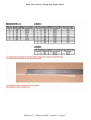
1
OWNER’S GUIDE
OF
BasiK Air Concept
2010 RN 97 - 83340 Le Luc - France
tel: +33 (0)494 99 12 36 - [email protected]
Edition n°1 - february 2009 - revision 1
Table of contents
Overview
page 2
Parts List
page 3
Closing loops lenght
page 4
AAD (Argus, Cypre and Vigil) Installation
page 5
Closing the reserve container
page 6-10
Setting the main canopy
page 11
New main toggles
page 12
Closing the main container
page 13-19
RSL and handles
page 20
End fitting housing
page 21-23
3 ring assembly and gear check
page 24
Rigging and maintenance
page 25
Additional for Student version
page 26-31
Pictures
page 32
Advance
Size
SN#
Manufacturing
date
.................................................
.................................................
.................................................
.................................................
Edition n°1 - february 2009 - revision 1 - page 1
Introduction
After creating the Advance H/C,BasiK Air Concept is proud to present to you its new H/C named
Seven. We have been working hard to have this new Advance Seven ready. It keeps the same
general envelopp with the no reserve side flaps concept but a lot of new features have been
added to it. Why Seven? Only because it has 7 new main points. You will discover into this manual these new features and how to deal with them.
It tooks several years to design and test the Seven between its first original draw and its first
sales. All these passing years have helped us to verify how we could integrate our ideas and how
they could be worth by keeping the main idea of the Advance OUT system. You just have to follow all the instructions of this manual to assemble and pack the Seven H/C. Just remember, you
must be qualified to do such work, if not, ask your rigger to do it for you.
Advance Seven comes with the following options included at no extra cost:
Hip rings
Velcro-free toggles
Front loop risers
Custom harness size
Custom colors*
Kill-line main pilot chute
Riser covers secured by magnets
3D spacer foam back pad and leg pads
Throw out pouch with free-fly pad secured by magnets
Z knife on ring cover
Leg strap junction
* According to available list
The Advance Seven container system has been tested in accordance with AS-8015B. It is
approved under TSO C-23d and French certification QAC 121.
Edition n°1 - february 2009 - revision 1 - page 2
Parts List
The Advance Seven container system is delivered with the following components:
Harness and container
Main risers with steering toggles
Main deployment bag with kill-line pilot chute or bunjie installed
Breakaway handle
Reserve handle
Reserve free bag and bridle*
Reserve Pilot chute**
Reserve steering toggles
Main closing loop
Reserve closing loop
One extra main closing loop
Rubber bands
Owner’s guide
All Advance Seven harnesses are manufactured AAD-ready. FXC setup is an option.
No other brand component can be used with the Advance Seven container system.
All components listed above can also be purchased individually from BasiK Air Concept and its
official dealers. Seven limitations of use are 110 kg at 150 kts.
BasiK Air Concept cannot be held responsible in case of an use over these weight and speed
limits except for Student sizes 3 and 4 which are certified at the same airspeed but at a weight
limit of 130 kg.
* Only the Advance Seven reserve free bag can be used with the Seven container system.
** Only the Advance OUT reserve pilot chute can be used with the Advance OUT and Seven
container systems.
Repack cycle must be done up to your own country regulations. We allow a 1 year packing cycle
maximum for all of our Advance H/C systems.
Edition n°1 - february 2009 - revision 1 - page 3
Main and reserve closing loop lenght chart
Edition n°1 - february 2009 - revision 1 - page 4
AAD setup
Install the AAD main unit into its pocket, cable connexion must be facing downward. Stow
remaining cables and close the protecting scratch flap. Route the cutter and the control unit
into the white type 4 /1.5” channel. Put the cutter into its protective chanel and do not forget
to install the closing loop through the cutter hole. Route the control unit toward the collar
then through the slit at collar level.
Slip the control unit into the back-pad and stowed it in its slot. Close the protecting flap.
Installation is done. It is possible to install the control unit in the right ring cover (only
available under request for student unit with adapted cable lenght).
For Advance Seven IN container type, please report to the Advance IN additional guide.
Edition n°1 - february 2009 - revision 1 - page 5
Reserve container closing instructions for the Advance SEVEN
This chapter deals with the procedures for packing a ram air reserve canopy into the Advance
Seven container system. Assembly and packing of the reserve must be accomplished by a
certified rigger, or by the manufacturer of the Advance Seven container system. Before
starting to pack, fill your rigger’s log book copy down the type of canopy, S/N and DOM from
canopy data panel.
Required tools:
One temporary pin (with warning flag attached)
One pull-up cord (120 cm minimumlength)
One packing paddle or long bar
One T bar
Two 15 cm strips of 2,54 cm velcro loop
The closing loop must be at the right length (report to the last page for the appropriate length).
Make a thorough inspection of all components of the reserve parachute. Reserve pilot chute,
reserve bridle, free bag, reserve canopy, lines, slider, connector links, harness and container
system.
Follow the canopy manufacturer’s directions for the inspection, attachment to risers, routing of
control lines, attachment of steering toggles, setting deployment brakes, and for flaking and
folding the reserve canopy. We highly recommends the Pro-pack for all ram-air reserves packed
into the Advance Seven container system. This Pro-pack can be done in different maners. The
purpose of this guide is not to explain to you how to pack a reserve canopy but only how to set
the free-bag into the Advance Seven container system. However, because of the new shape of
the reserve container, it is important to fill correctly both upper corners and the bottom of the
free-bag. Avoid to have a lot of material in the sides of the free-bag. This filling must
be symmetrical to help you get a good secure hold of the two upper side closing devices.
Set the deployment brakes on each side by pulling the control line down through the guide ring
until the brake loop passes through it. Insert the stiffened upper portion of the toggle through
the loop and pull it up tightly against the guide ring. S-fold the slack between the toggle and the
brake-set, and stow it under the elastic located on top of the guide ring. Mate the scratch on
the toggle with the one located on the riser.
Edition n°1 - february 2009 - revision 1 - page 6
Place the bulk of canopy on each bottom side of the free bag. Lock the mouth of the
free-bag by making two stows with the suspension lines in the safety stow. Stow the remaining
of suspension lines in the line-stow pouch on the back of the bag. This is where it is useful to
use the velcro strips mentionned in the list of tools. Cover the hook velcro on the pouch with the
strips of loop velcro while stowing the lines into the pouch. S-fold the lines making sure to match
the full width of the pouch.
Leave a slack of 40 cm from the free bag to the risers. Remove the strips of loop velcro and
mate the velcro at the mouth of the pouch, making sure that none of the suspension lines are
trapped by the closure.
Edition n°1 - february 2009 - revision 1 - page 7
Prepare the reserve container. If the AAD is installed, thread the reserve closing loop through
the AAD cutter (if not already done), and then the pull-up cord through the reserve closing loop.
Lay the reserve risers in the container so that the connector links are in the lower corners of
the container.
Thread the pull-up cord and the reserve closing loop through the grommet of the free-bag. Lay
the bag in the container with the lines stow pouch facing down. Lay the lines protection flap
located over the AAD pouch on the free bag. Secure with the temporary pin. The bridle must
stay over the reserve container. S-fold 30 cm of bridle up and down on the upper part of
thefree bag. Close the two upper closing devices by setting them over the two corners of the
free bag. Thread the elastic through the grommet and secure it with 3 cm maximum of the free
bag bridle after making a needle fold to the bridle. Always keep the bridle toward the reserve
container to avoid any misrouting during the closing procedure.
“S” fold the remaining free-bag bridle up and down below the closing loop axis. Route the
pull-up cord through the pilot chute and out through the cap. Be careful to not route through in
and out the springs. Seat the lower end of the pilot chute on top of the free bag grommet and
bridle, keeping the pull-up cord tight.
Compress the pilot chute and lock it with the temporary pin. Now pull all fabrics out from under
the top plate so that the pilot chute fabric is spread out. At this point, check the lenght of the
closing loop. If the pilot chute’s top plate can rock back and forth or from side to side, the loop
is too long. Shorten it so that when the pilot chute is compressed and locked with the
temporary pin, the top plate is firmly seated in the nest formed by the shape of the free bag.
Edition n°1 - february 2009 - revision 1 - page 8
Fold or roll the pilot chute fabric at the top of the pilot chute parallel with the top of the
container, and push this roll under the top plate of the pilot chute. Stow the remaining of the
pilot chute fabric down the sides of the pilot chute top plate. Push the excess fabric under the
pilot chute top plate. The pilot chute fabric excess must be thiner fold than the bottom flap and
kept in the middle.
Make sure to keep the point of the fan narrow and tight to the middle bottom of the pilot chute
plate. Close the bottom flap and secure it with the temporary pin.
Close the top flap and secure it with the temporary pin.
Push the side tuck flaps under the ears of the bag, remove the pull up cord and count your tools.
Remember it is mandatory to seal the reserve pin to match TSO’d regulations.
Edition n°1 - february 2009 - revision 1 - page 9
With the RSL system, thread the reserve cable through the upper guide ring then through the
R.S.L. ring, then through the lower guide ring.
This system doesn’t replace the normal activation of the reserve handle. As any mecanical
system, it might not work. Remember, you always need to make the full safety procedure,
cutaway the main and activate the reserve. For the few cases where immediate reserve
activation may not be desired, the Advance Seven RSL features quick-release which can be used
to disconnect it. This quick release consists of a snap-shackle which is normaly attached to a
small ring on the inboard side of the left main riser. Release of the snap-shackle is
accomplished by a quick tug on the red ribbon attached to the release ring. Some jumpers feels
that the RSL should not be connected during Canopy Relative Work, preferring to disconnect
from the main and then fall free of a “wrap“ before deploying the reserve. Also, if winds are
high, the jumper may disconnect the main canopy after landing to avoid being dragged. In this
case the quick-release can be used prior to landing to prevent an non desired activation of the
reserve.
Assembling the RSL system
There are two rings mounted on the reserve top flap near the end of the ripcord housing. After
installing the reserve ripcord in the housing, the cable must be routed first, through the upper
guide ring, then through the RSL ring, located at the end of the bridle and at last through the
lower guide ring. It is important to assemble the cable with the rings in this exact order. Before
the reserve container is closed, the RSL bridle must be routed out from under the reserve pin
flap at the upper left. The velcro of the RSL bridle should be mated to the velcro on the left
reserve riser to bring the bridle over the shoulder. Then the snap-shackle can be connected to
the small ring behind the inboard side of the left main riser. There should be enough slack in
the RSL bridle so that the main riser can be pulled in any direction without putting any tension
on the reserve riser. Any slack in the RSL bridle near the reserve flap must be tucked under the
reserve top flap. Caution although the RSL is considered to be very dependable, it is only a backup, and should never be relied upon entirely for activation of the reserve. In the event of a
breakaway or cutaway, the jumper should follow through by pulling the reserve ripcord handle
as if there was no RSL. It must also be understood that this system will not operate in the event
of a total non opening of the main container. Connect the RSL snap-shackle to the small ring
behind the inboard side of the right main riser, your RSL system is now actived. To disactivate
it, disconnect the snap-shackle.
Edition n°1 - february 2009 - revision 1 - page 10
Advance Seven main canopy setting instructions
This chapter details instructions of setting the main canopy into the main Advance
Seven container system.
Assembly and packing of the main canopy must be done by a certified person or by the person
making the jump, in accordance with. These persons must follow the canopy manufacturer
instructions for these operations.
Basik Air Concept cannot be responsible in case of an assembly or packing or setting mistake.
1) Carefully inspect the main canopy, suspension lines, steering lines, slider and grommets,
connector links and other parts of the main canopy before assembling it with the risers. Replace
or repair any worn or damaged parts. Inspect the deployment bag, bridle, and pilot chute as well.
2) Attach the main canopy to the main risers, making sure that the canopy is facing the same
direction as the container system. Each suspension line must be clear all the way from its
attachment point through the slider grommet to the connector link without passing around any
other line. Make sure the steering lines are clear from the trailing edge of the canopy through
the slider grommets and through the guide rings on the rear risers to the steering toggles. Each
steering toggle must be securely tied to its control line at the location specified by the canopy
manufacturer.
Make sure as well that the connector links are tight enough so that they cannot be loosened with
the fingers alone. If soft links are used, please report to the canopy manufacturer to install and
secure them.
3)Attach the connector link of the main bridle (located inside the main bag) on the ring
located at the top of the main canopy and tighten it enough.
Edition n°1 - february 2009 - revision 1 - page 11
Installation of new main toggles manufactured from 11/02/09
Run the steering line into the tape loop located under the pin setting.
Run the toggle’s lower part into the steering line lower loop.
Run the entire toggle into the loop and exit it at the top end of the straight pin.
Squeeze the knot.
Beware: The knot must be only set on the tape loop located under the pin setting.
Edition n°1 - february 2009 - revision 1 - page 12
Set the deployment brakes on each side by pulling the control line down through the guide ring
until the brake loop passes through it.
Insert the pin of the toggle through the loop and push it up tightly against the guide ring. Insert
the pin of the toggle into its locking stow. Insert the lower part of the toggle into its locking
stow too.
S-fold the slack into the channel located behind the riser.
Before setting the main canopy into its bag, you must cock the kill line of the main pilot chute
(if used). At this point, refer to canopy manufacturer's guidelines for packing instruction.
Edition n°1 - february 2009 - revision 1 - page 13
IMPORTANT: The excess slack of lines must not exceed 40 cm
Edition n°1 - february 2009 - revision 1 - page 14
Lay the risers between the sides of the reserve container and the risers covers.
Close the risers covers and stow the risers straight on the side of the reserve container.
Edition n°1 - february 2009 - revision 1 - page 15
Before setting the main bag into the container be sure to have cock
the kill line system of your main pilot chute (if used). The colored mark must be visible in the
window. If not re-cock the system.
On the left picture the
pilot chute is ready. On
the right shot the kill
line system is not
cocked.
Set the main bag into the container with the line stows oriented toward the bottom. This
position is important; if the line are oriented toward the top, it may be more difficult for the
pilot chute to extract the bag. Also, the lines can snag easily any part of the container.
Pilot chute bridle must be route out toward the upper right side. Closing flap order is:
-Bottom -Up -Left -Right
Edition n°1 - february 2009 - revision 1 - page 16
Secure with the pin located on the pilot chute bridle. Bridle must be laid verticaly as shown on
the middle above shot. Close the main protecting flap and stowed the remaining bridle under the
right main flap toward the corner and the pilot chute pouch.
Edition n°1 - february 2009 - revision 1 - page 17
Lay the pilot chute out flat with mesh side up and fold it in half over the bridle. Now fold the
curved side up to the top and stow 3 folds of the bridle in the middle.
Fold one side of the pilot chute over the opposite side, and then roll it tightly until having
cylindrical shape.
Keep tight the pilot chute when stowing it into the pouch.
Edition n°1 - february 2009 - revision 1 - page 18
Tuck the slack of bridle into the pouch, then tuck the pilot chute. Spread widely the pilot chute
into the pouch.
Set the FF pad into its place.The tuck tab with magnets goes into the pouch the opposite part
must be set in the container’s corner. Avoid to twist the pouch’s mouth where the magnets are
installed.
Closing the Advance Seven container with a pull-out opening system
FIRST COCK THE KILL LINE OF THE PILOT CHUTE
1) Mate the magnet from pull-out pad with the magnet located under the pull-out pad cover at
the right hand corner of bottom flap.
2) Stow the bridle in folds 15 to 20 cm long, and lay the folded bridle across the upper part of
the bag. Be sure not to tuck these folds down between the bag and the bottom of the reserve
container. Doing so may delay the action of pilot chute.
3) Loosely fold the pilot chute and lay it across the bag.
4) Close the flaps as follow, bottom-top-left-right, securing the closing loop with the pin.
5) Tuck the slack under the right side flap.
7) Close the protecting flap.
Be sure that the connecting knot between the pilot chute and the briddle is not trap under the
flap.
Edition n°1 - february 2009 - revision 1 - page 19
RSL system and handles
Connect the snap shackle on the dedicated ring located on the left main riser. Your RSL is now
ativated. To disconnect it, just pull the tab and remove the shackle from the ring.
Hooktable and pillow breakaway handles. Reserve handle
Edition n°1 - february 2009 - revision 1 - page 20
ADDITIVE TO ADVANCE HARNESS-CONTAINER USER MANUALS
MANUFACTURED BY BASIK AIR CONCEPT
After long researchs and many testings, we have developped a new type of cutaway housing
terminal end. Because of its new design we have decided to make this additive of the user manual
to protect you against misrouting. Its goal is to show you the right way to install the breakaway
release system with this new terminal end.
You will find in the following pages, all assembly stages but also a demonstation in last page of
the mistake to be avoid.
This new design will bring you all satisfaction because of its simplicity of use and also because it
increases the security which characterized this new system.
Basik Air Concept- 2010 RN 97 - 83340 Le Luc - France
Tel: 33-(0) 4 94 99 12 36 - Fax: 33-(0) 4 94 39 89 37 - E-mail: [email protected]
Edition n°1 - february 2009 - revision 1 - page 21
As you can see the old grommet has been replaced by a cylindrical shape inox piece equiped with
several windows. Advantages of this sytem are:
Same shape as the breakaway housing
Complete protection of the white loop
No more side setup of the terminal end
No more cable sucking possibility
This terminal end has 4 windows.
1, in which the cable run through, 2 little rounds in which the white loop goes and 1 long oval
which allow to install the cable and to check the routing.
View of the cable running into the housing and the terminal end.
Routing of the white loop through the riser’s grommet.
Running of the white loop through one of the little round window.
Edition n°1 - february 2009 - revision 1 - page 22
Fit the cable through the white loop and stow the remaining cable. Assembly must be done like
on this photo.
Final setting of the breakaway housing on the 3 ring release system.
Routing mistake.
Beware to not run the white loop by or through the large oval window. If you do so,
a non intentionnal cutaway will happened. Check carefully that the white loop
routing goes exclusively by both little round windows.
The above photo shows the routing mistake to be avoided.
Basik Air Concept, wish you good jumps with this new system.
Edition n°1 - february 2009 - revision 1 - page 23
Assembly of the 3-rings system
1) Thread the cable into its housing and stick the handle to the harness. The handle should be
positioned as close to the ends of the housings as possible so that no cable is exposed.
2) With the rings of the riser facing toward the floor, pass the ring on the end of the riser
through the large harness ring from above. Fold it back toward the canopy and riser.
3) Thread the smallest ring through the middle ring in the same way, but make sure it does not
pass through the large ring.
4) Thread the white loop through the small ring only and then through the riser grommet so it
pokes out at the back of the riser.
5) Thread the white loop through the grommet on the end of the cable housing. The flat side of
the cable housing grommet should lay against the riser.
6) Thread the yellow cable through the white loop, making sure the loop is not twisted. Make
sure you do not bend the cable too sharply or kink it. Insert the free end in the channel on
the back of the riser.
7) Repeat the above steps with the other riser.
Before jumping the Advance Seven container system
Before using the Advance Seven container system, you must read this guide and proceed to the
following checks. These checks must be done at least once a month or after 50 jumps. The
maintenance (if needed) must be done by a qualified person (up to the country of use
regulations).
Velcros, spandex pouch and reserve elastic bands closing system
Main and reserve closing loops
Harness, all webbings, chest strap and leg straps
Stiches of the container and harness
Routing of handles, cables and bridles
Housings and cables
Main pilot chute and bridle
3-rings system
Main risers
All hardwares
Grommets
Main deployment bag
RSL system if installed on your rig
Components life time
Harness container 20 years
Reserve spring pilot chute must be replaced if the spring force is less than 14 kg and if any wear
appear on the fabric.
Reserve bag same as container
Main pilot chute must be change every 350 jumps
Inner Kill line must be change every 200 jumps
The complete system must be check at least every year and worn components must be changed
if necessary.
Edition n°1 - february 2009 - revision 1 - page 24
Rigging and maintenance
They are set in 2 categories:
1) Class 1 repair
Everything can be done by a certified rigger except the following:
Harness - reserve container and all parts identified as a “Part Number” and listed into the
capability list (reserve bag - reserve pilot chute - reserve ripcord).
2) Class 2 repair
All work on the harness and reserve container must be done by the manufacturer or a Master
Rigger. No one else is allowed to proceed to this kind of repair. Only raw material allowed by
BasiK Air Concept must be used.
Only the spare parts with a BasiK Air Concept “Part Number” and listed on BasiK Air Concept
capability list are allowed to be used with the Advance Seven System.
Container cleaning
Use a textile spray for any natural or chemical stain. If a washing must be made, put the H/C
into a textile bag with natural light soap and used cold water. The drying must be done under
shade and at least for 15 days to eliminate the water from the inside foam.
NEVER USED CHEMICAL PRODUCT OR DETERGENT AND NEVER PROCEED TO A DRY
WASHING.
Edition n°1 - february 2009 - revision 1 - page 25
Additional for the Seven Student version
The Seven’s main toggles are pin free. Set the deployment brakes on each side by pulling the
control line down through the guide ring until the brake loop passes through it. Insert the
stiffened upper portion of the toggle through the loop and pull it up tightly against the guide
ring. S-fold the slack between the toggle and the brake-set, and stow it in the tape loop.
The main lift web of the Seven Student has a color coding system which allow a perfect
symmetry of the harness. Adjust the same color on each side and stow the remaining webbing
into the flaps.
Edition n°1 - february 2009 - revision 1 - page 26
AFF secondary handle
The AFF secondary handle can have a secondary pilot chute which allow to open directly the main
container.
Start by threading the yellow cable into the lower left tape loop. Then thread it into the pouch
tape loop and alternate each one till the end.
Pack the pilot chute as usual.
Put the pilot chute against the container with the bridle slack between the pilot chute and the
pouch.
Edition n°1 - february 2009 - revision 1 - page 27
Stow the system correctly and set the upper yellow cable the same maner as over. Start by the
container tape loop first.
Close the pouch and install the handle.
Edition n°1 - february 2009 - revision 1 - page 28
How the system works?
When pulling the handle both cables released and the pouch became free.
Do not hold the handle, just throw it away. The secondary pilot chute inflates immediatly like a
pull-out system and pull the pouch. When in tension the main pilot chute get out from the pouch
and open the main container.
IF YOU DO NOT WANT TO USED THE SECONDARY PILOT CHUTE, JUST REMOVE IT
FROM THE SYSTEM. THIS WILL ALLOW YOU TO OPEN THE POUCH ONLY AND YOU
WILL HAVE TO EXTRACT THE PILOT CHUTE TO HAVE THE CONTAINER OPEN.
Edition n°1 - february 2009 - revision 1 - page 29
How to assemble the sleeve
View of the sleeve
Thread the sleeve loop end through the main canopy bridle.
Then thread the entire sleeve through the sleeve loop end. Thread the main pilot chute bridle
into the main canopy bridle and route the opposite loop end through it.
Squeeze the knot to have these 3 bridle attached together.
Reverse the sleeve and run the main pilot chute bridle through the pilot chute bottom tapes.
Then thread the pilot chute cap through the bridle loop end.
Squeeze the knot.
Edition n°1 - february 2009 - revision 1 - page 30
Put the canopy into the sleeve by spreading it all the way.
Fold the remaining of the canopy and insert it into the sleeve.
Flod up the closing flap with the lines right in the center and close it with the 2 line stows.
Finish the line stowage and close the protecting flap.
Put the sleeve in the container, fold it and close the container. If you are using a spring pilot
chute, set it right in the middle of the tray over the sleeve and close the container.
Edition n°1 - february 2009 - revision 1 - page 31
Edition n°1 - february 2009 - revision 1 - page 32