1
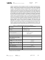
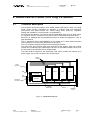
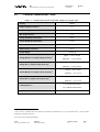
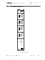
Technical
Information
Manual
Revision n. 0
12 October 2006
MOD. A4602
CMS SILICON TRACKER
CCU RING PSM
MANUAL REV. 0
NPO:
00113/05:A4602.MUTx/00
CAEN will repair or replace any product within the guarantee period if the Guarantor declares that the
product is defective due to workmanship or materials and has not been caused by mishandling,
negligence on behalf of the User, accident or any abnormal conditions or operations.
CAEN declines all responsibility for damages or
injuries caused by an improper use of the Modules due
to negligence on behalf of the User. It is strongly
recommended to read thoroughly the CAEN User's
Manual before any kind of operation.
CAEN reserves the right to change partially or entirely the contents of this Manual at any time and without
giving any notice.
Disposal of the Product
The product must never be dumped in the Municipal Waste. Please check your local
regulations for disposal of electronics products.
User's Manual (MUT)
Title:
A4602 CMS Silicon Tracker CCU Ring PSM
Revision date:
11/10/2006
Revision:
0
TABLE OF CONTENTS
1.
2.
EASY EMBEDDED ASSEMBLY SYSTEM ............................................................................................5
1.1
FUNCTIONAL DESCRIPTION .....................................................................................................................5
1.2
THE CAEN MULTICHANNEL POWER SUPPLY SYSTEM OVERVIEW ........................................................6
1.3
THE MOD. A1676A BRANCH CONTROLLER OVERVIEW .........................................................................8
A4602 CMS SI-TRACKER CCU RING PS MODULE ..........................................................................9
2.1
TECHNICAL DESCRIPTION .......................................................................................................................9
2.2
CHANNEL CHARACTERISTIC TABLE .....................................................................................................10
2.3
FRONT PANEL COMPONENTS .................................................................................................................11
2.4
TECHNICAL SPECIFICATIONS ................................................................................................................12
2.4.1
Packaging ....................................................................................................................................................12
2.4.2
Front panel connections ..............................................................................................................................12
2.4.3
Front Panel Displays...................................................................................................................................12
2.4.4
Other components........................................................................................................................................12
2.4.5
Backside connections...................................................................................................................................13
2.5
3.
SAFETY INFORMATION AND INSTALLATION REQUIREMENTS............................................15
3.1
3.1.1
4.
INTERLOCK JUMPERS ............................................................................................................................14
GENERAL SAFETY INFORMATION ..........................................................................................................15
Injury Precautions .......................................................................................................................................15
3.2
SAFETY TERMS AND SYMBOLS ON THE PRODUCT ................................................................................16
3.3
INSTALLATION......................................................................................................................................16
OPERATING MODES .............................................................................................................................17
4.1
OUTPUT CONTROL AND MONITORING ...................................................................................................17
4.1.1
Internal Trip ................................................................................................................................................18
4.1.2
PSU OPC Items ...........................................................................................................................................19
4.1.3
Output Channel OPC Items .........................................................................................................................21
NPO:
00113/05:A4602.MUTx/00
Filename:
A4602_REV0.DOC
Number of pages:
24
Page:
3
User's Manual (MUT)
Title:
A4602 CMS Silicon Tracker CCU Ring PSM
Revision date:
11/10/2006
Revision:
0
LIST OF FIGURES
FIG. 1.1 – SYSTEM’S BLOCK DIAGRAM ...................................................................................................................6
FIG. 2.1 – A4602 BLOCK DIAGRAM.......................................................................................................................9
FIG. 2.2 – A4602 FRONT PANEL ..........................................................................................................................11
FIG. 2.3 – A4602 CONNECTION BOARD ...............................................................................................................13
FIG. 2.4 – A4602 INTERLOCK JUMPERS ...............................................................................................................14
FIG. 4.1 – STATUS WORD .....................................................................................................................................22
LIST OF TABLES
TABLE 1.1 – TECHNICAL SPECIFICATIONS OF THE SY 1527 MAINFRAME ...............................................................7
TABLE 2.1 – CHANNEL CHARACTERISTICS OF THE MOD. A4602 POWER SUPPLY UNITS ....................................10
TABLE 4.1 – A4602 PSU ITEMS...........................................................................................................................20
TABLE 4.2 – A4602 OUTPUT CHANNEL ITEMS .....................................................................................................23
NPO:
00113/05:A4602.MUTx/00
Filename:
A4602_REV0.DOC
Number of pages:
24
Page:
4
User's Manual (MUT)
Title:
A4602 CMS Silicon Tracker CCU Ring PSM
Revision date:
11/10/2006
Revision:
0
1. EASY Embedded Assembly System
1.1
Functional description
EASY (Embedded Assembly SYstem) is the new CAEN power supply solution for
operation in magnetic field and radioactive environment. CAEN has been involved for
more than a decade in developing different solutions for the main LHC experiments,
where the electronic equipment of the experiment is dealing with high dose radiation and
intense magnetic field. In order to provide safe and reliable operations in such hostile
areas, CAEN started tests with rad-tolerant components and magnetic field resistant
solutions, patenting the new technology that is now used in this new line of products.
Moreover, though designed for harsh environment, the EASY modules can work also in
normal condition with excellent performance. In the new architecture, the power supply
can be located directly in the hostile area, where the EASY modules provide a wide
variety of output voltages to satisfy the requirements of most detectors and front-end
electronics. The control of the EASY power supply system is done remotely using a
Branch Controller (Mod. A1676A) plugged in a SY1527 or SY2527 mainframe located in
the control room. Each A1676A branch controller can handle up to 6 EASY crates: in this
way, one SY1527 power supply system, for example, housing up to 16 A1676A boards,
can handle up to 96 EASY systems. The EASY crate can house up to 10 boards,
depending on the boards’ width. The branch controller is the interface between the
mainframe (SY1527 or SY2527) and the remote boards in the EASY crate: its role is to
configure the EASY channels as if they belong to the supply unit slot in which the branch
controller is located. All the channels of the EASY boards will be considered as channels
of the branch control board, thus hugely increasing the number of channels the system
can handle. Through the mainframe, the provided and fully reliable OPC server permits
an immediate and “automatic” interfacing with the custom control software; moreover, a
C-library for Windows and Linux is available as well. The EASY crate can be used with
an air and/or water intercooler and its standard width fit the rack mounting. Fig. 1.1
shows the system’s block diagram.
NPO:
00113/05:A4602.MUTx/00
Filename:
A4602_REV0.DOC
Number of pages:
24
Page:
5
Title:
A4602 CMS Silicon Tracker CCU Ring PSM
User's Manual (MUT)
Revision date:
11/10/2006
CONTROL ROOM
Revision:
0
HOSTILE AREA
Power Line
SY1527
48V
POWER
SOURCE
48V
SERVICE
POWER
SOURCE
CONTROL
LOGIC
POWER FAILURE
INTERRUPT
DC-DC
V+
S+
SV-
DC-DC
V+
S+
SV-
DC-DC
V+
S+
SV-
DC-DC
V+
S+
SV-
DC-DC
V+
S+
SV-
DC-DC
V+
S+
SV-
EASY Module
P. Service Line
BRANCH
CONTROLLER
CONTROL
LOGIC
SY1527 SYSTEM MAINFRAME
Control Bus
EASY Module
48V
BACKUP
BATTERY
Fig. 1.1 – System’s block diagram
1.2
The CAEN Multichannel Power Supply System Overview
The SY1527 system is the fully equipped experiment version of a new line of power
supply systems which represent CAEN's latest proposal in the matter of High Voltage
and Low Voltage Power Supplying. This system outlines a completely new approach to
power generation and distribution by allowing the housing, in the same mainframe, of a
wide range of boards with different functions, such as High/Low Voltage boards, generic
I/O boards (temperature, pressure monitors, etc.) and branch controllers, where the latter
are used to control other remote generators and distributors. Modularity, flexibility and
reliability are the key-points of its design, enabling this module to meet the requirements
needed in a wide range of experimental conditions, which range from those of LHC
experiments, where the features of this model find prior application, to those of other less
challenging, but still demanding, High Energy Physics experiments.
The mainframe is housed in a 19"-wide, 8U-high euro-mechanics rack and hosts four
main sections:
- the Board Section, with 16 slots to house boards, distributors and branch controllers;
- the Fan Tray Section, housing 6 fans arranged on two rows;
- the Power Supply Section, which consists of the primary power supply and up to 3
power supply units;
- the CPU and Front Panel Section which includes all interface facilities.
The User Software Interface features the usual friendliness of the previous CAEN
systems which now also includes a 7.7" colour LCD. A wide choice of interface facilities
provides full communication compatibility with the previous systems and the feasibility of
controlling heterogeneous external devices. Modularity has been one of the leading
criteria in the design and development of the system: both the Power Supply Section and
the Board Section are completely modular. The Power Supply Section allows different
configurations with up to 3 power supply units per mainframe (up to 2250 W), while the
Board Section can house up to 16 boards able to fulfil different functions. A complete line
of power supply boards and distributors has been specially developed for this new
system. The minimum system configuration consists of the primary power supply, one
Power Supply Unit and one board. The system allows also to deal with power supply
NPO:
00113/05:A4602.MUTx/00
Filename:
A4602_REV0.DOC
Number of pages:
24
Page:
6
User's Manual (MUT)
Title:
A4602 CMS Silicon Tracker CCU Ring PSM
Revision date:
11/10/2006
Revision:
0
solutions composed by “branch controllers” (housed in the system main frame) and ondetector “remote boards” (manufactured in order to be magnetic field and radiation
tolerant). Channel trip control on other crates is performed via four external differential
trip lines. A sophisticated trip handling via software allows to control and correlate trip
conditions on the channels of the crate as well as of other crates connected to it. Live
insertion and extraction of the boards, which reduces the down time of the global system,
and easy access to the computing core and peripherals of the system complete the
system flexibility. Easy interfacing is another key-point of the SY1527 system, which can
be connected to SY127 and SY527 systems. The Ethernet interface (TCP/IP) allows both
an easy Telnet access and the connection via OPC Server to a SCADA control system.
Enhanced software programming features a unified command set independent from the
interface used to communicate with the system. The Power Supply Section and Board
Section can be externally synchronised via front panel connectors. Multi-layered access
to the system via Intranet is foreseen through the management of several custom user
profiles. In particular, three different access levels have been implemented: Guest, User
and Administrator, each of which with password protection. Handy maintenance and
upgrading, which constitute a major issue in the reliability of a system, are further
guaranteed by the possibility of accessing and servicing the system via network facilities.
Actually, the Telnet access facility allows remote debugging and technical support of the
system, including future firmware upgrading. For a detailed description of the SY 1527
Universal Multichannel Power Supply System please refer to the SY 1527 User's Manual.
Table 1.1 – Technical specifications of the SY 1527 mainframe
Packaging
- 19"-wide, 8U-high Euro-mechanics rack;
- Depth: 720 mm.
Weight
-Mainframe (*): 24 kg
-Mod. A1532: 3.2 kg
Voltage range: 100/230 V
Power requirements
Frequency: 50/60 Hz
Power: 3400 W
Max. number of boards per crate
16
Max. number of power supply
units per crate
3
Primary power supply output (Mod.
A 1531)
Power supply unit output (Mod.
A 1532)
Max. output power
± 12 V, 8 A
+5 V, 20 A
+48 V, 15.6 A
2250 W
Operating temperature
From 0°C (dry atmosphere) to +40°C
Storage temperature
From -20°C (dry atmosphere) to +50°C
(*) One Primary Power Supply (Mod. A 1531) and one Power Supply Unit (Mod. A 1532) are
included; boards are not included.
NPO:
00113/05:A4602.MUTx/00
Filename:
A4602_REV0.DOC
Number of pages:
24
Page:
7
User's Manual (MUT)
1.3
Title:
A4602 CMS Silicon Tracker CCU Ring PSM
Revision date:
11/10/2006
Revision:
0
The Mod. A1676A Branch Controller overview
The Mod. A1676A EASY Branch Controller is implemented in a single width
SY1527/SY2527 board. Once plugged in, the Branch Controller must be linked to the
EASY crates (placed in the “hostile area”), via front panel connectors (Control and Power
Supply). The A1676A is the interface between the mainframe and the remote boards in
the EASY crate. It configures the EASY channels as if they belong to the slot in which the
branch controller is located: the channels of the EASY boards operate as channels of the
A1676A. Up to six EASY crates can be controlled by one A1676A. The provided software
tool allows the User to configure the A1676A to operate with any EASY crate layout.
NPO:
00113/05:A4602.MUTx/00
Filename:
A4602_REV0.DOC
Number of pages:
24
Page:
8
User's Manual (MUT)
Title:
A4602 CMS Silicon Tracker CCU Ring PSM
Revision date:
11/10/2006
Revision:
0
2. A4602 CMS Si-Tracker CCU Ring PS Module
2.1
Technical description
This document shows the features of the CAEN A4602 CMS Silicon Tracker CCU Ring
Power Supply Module, developed for operation in magnetic field and radioactive
environment. One A4602 houses four ”Power Supply Units” (PSU0..3), completely
floating and handled by a microcontroller, via optoisolators.
Each channel provides a 2.5 V output on the load, adjustable within a ±10% range, with a
7 A maximum current; a maximum 6 V line drop can be compensated via sense wires.
Each PSU is equipped with two temperature sensors to inhibit the regulators in case of
high temperature.
The LV regulators ensure the stabilisation of the voltage up to 150m distance (senses
wires technique) on active loads, filtered with up to 600 µF.
The LVs are protected against senses wires exchange and shorts.
The board front panel houses LEDs and channels monitor signals, while the channel
outputs are provided through a DB female connector on the board backside, which must
be connected to the loads through an adapter board.
The board shall be inserted in the EASY4000 crate, which provides the external 48 V
power supply, the control bus and the four Interlock lines.
bus bar
outputs
output
connector
SSF
PSU3
PSU2
PSU1
PSU0
aux DCDC
link
opto
controller
backplane
connector
interface
electronics
bus bar
48Vpwr
backpanel
board
Fig. 2.1 – A4602 Block Diagram
NPO:
00113/05:A4602.MUTx/00
Filename:
A4602_REV0.DOC
Number of pages:
24
Page:
9
User's Manual (MUT)
2.2
Title:
A4602 CMS Silicon Tracker CCU Ring PSM
Revision date:
11/10/2006
Revision:
0
Channel Characteristic Table
Table 2.1 – Channel characteristics of the Mod. A4602 Power Supply Units
Floating
Polarity:
Output voltage (connector):
8V
Output voltage (load):
2.5 V
Max. Output Current:
7A
Voltage Set/Monitor Resolution:
5 mV
Current Set/Monitor Resolution:
10 mA
VMAX software:
2.75 V
VMAX software resolution:
5mV
Voltage Ripple: 1
< 20 mV pp
typical: ± 0.3% ± 30 mV
Voltage Monitor vs. Output Voltage Accuracy: 2
maximum: ± 0.3% ± 50 mV
typical: ± 0.3% ± 30 mV
Voltage Set vs. Output Voltage Accuracy: 5
maximum: ± 0.3% ± 50 mV
typical: ± 2% ± 0.05 A
Current Monitor vs. Output Current Accuracy: 5
maximum: ± 2% ± 0.1 A
typical: ± 2% ± 0.05 A
Current Set vs. Output Current Accuracy: 5
maximum: ± 2% ± 0.1 A
± 0.3 % (with sense wires)
Load Regulation: 5
± 2 % (without sense wires)
Output power:
1
56 W per channel
From 10 Hz to 15 MHz at full load; measured with the line terminated on a 10 µF capacitance and a 100 nF ceramic
capacitance in parallel to the load
2
From 10% to 90% of Full Scale Range
NPO:
00113/05:A4602.MUTx/00
Filename:
A4602_REV0.DOC
Number of pages:
24
Page:
10
User's Manual (MUT)
2.3
Title:
A4602 CMS Silicon Tracker CCU Ring PSM
Revision date:
11/10/2006
Revision:
0
Front panel components
Mod. V560E
Mod. A4602
CH ON
S+
OUT
TRIP
SRET
GND
GND
OVC
FAIL
INT.LOCK
CONN
PSU0
CH ON
S+
OUT
TRIP
SRET
GND
GND
OVC
FAIL
INT.LOCK
CONN
PSU0
CH ON
S+
OUT
TRIP
SRET
GND
GND
OVC
FAIL
INT.LOCK
CONN
PSU0
CH ON
S+
OUT
TRIP
SRET
GND
GND
OVC
FAIL
INT.LOCK
CONN
PSU0
PWR GOOD
COMM.
RESET0
SCA
LER
SI-TRACKER
CCU RING
POWER SUPPLY
Fig. 2.2 – A4602 Front Panel
NPO:
00113/05:A4602.MUTx/00
Filename:
A4602_REV0.DOC
Number of pages:
24
Page:
11
User's Manual (MUT)
Title:
A4602 CMS Silicon Tracker CCU Ring PSM
2.4
Technical Specifications
2.4.1
Packaging
Revision date:
11/10/2006
Revision:
0
The module is housed in a 8 TE wide, 6U-high mechanics.
2.4.2
Front panel connections
The board front panel houses four 8 pin female strips (one per PSU) which provide the
following monitor signals:
2.4.3
2.4.4
OVC:
Channel in overcurrent
RET:
Channel power return
OUT:
Channel test point
GND:
Channel Ground
S±:
LV sense Test Point
Front Panel Displays
CH ON LEDs:
Function: light up as one channel at least in
the relevant Power Supply Unit is on.
Type: red LEDs, one per PSU
PWGOOD LED:
Function: light up as the external +48 V
power and internal +/-12V and +17V
supplies are present.
Type: green LEDs, one per PSU
COMM LEDs:
Function: light up as the
communications take place.
Type: green LEDs, one per PSU
CONN LEDs:
Function: light up according to User’s
settings.
Type: green LEDs, one per PSU
TRIP LEDs:
Function: light up when at least one channel
of the PSU is turned off due to trip.
Type: red LEDs, one per PSU
INTERLOCK LEDs:
Function: light up as the interlock signal is
active.
Type: green LEDs, one per PSU
Other components
RESET pushbuttons:
NPO:
00113/05:A4602.MUTx/00
Filename:
A4602_REV0.DOC
Function: it allows to reset the PSU (one
pushbutton per Unit).
Number of pages:
24
Page:
12
User's Manual (MUT)
2.4.5
Title:
A4602 CMS Silicon Tracker CCU Ring PSM
Revision date:
11/10/2006
Revision:
0
Backside connections
OUTPUT connectors:
Mechanical specifications:
4 DBV17W2S500G30 15+2pin female
connector;
4 DB15 type female connector.
Fig. 2.3 – A4602 Connection board
NPO:
00113/05:A4602.MUTx/00
Filename:
A4602_REV0.DOC
Number of pages:
24
Page:
13
User's Manual (MUT)
2.5
Title:
A4602 CMS Silicon Tracker CCU Ring PSM
Revision date:
11/10/2006
Revision:
0
Interlock jumpers
FRONT PANEL
Each PSU has four interlock lines (ILK0÷3). Each line can be enabled (i.e. the PSU can
be put in Interlock via the enabled ILK line) by inserting the jumpers on the board side:
Fig. 2.4 – A4602 Interlock jumpers
NPO:
00113/05:A4602.MUTx/00
Filename:
A4602_REV0.DOC
Number of pages:
24
Page:
14
User's Manual (MUT)
Title:
A4602 CMS Silicon Tracker CCU Ring PSM
Revision date:
11/10/2006
Revision:
0
3. Safety information and installation requirements
3.1
General safety information
This section contains the fundamental safety rules for the installation and operation of the
boards. Read thoroughly this section before starting any procedure of installation or
operation of the product.
3.1.1
Injury Precautions
Review the following precautions to avoid injury and prevent damage to this product or
any products connected to it. To avoid potential hazards, use the product only as
specified. Only qualified personnel should perform service procedures.
Avoid Electric Overload.
To avoid electric shock or fire hazard, do not apply a voltage to a load that is outside the
range specified for that load.
Avoid Electric Shock.
To avoid injury or loss of life, do not connect or disconnect cables while they are
connected to a voltage source.
Do Not Operate Without Covers.
To avoid electric shock or fire hazard, do not operate this product with covers or panels
removed.
Do Not Operate in Wet/Damp Conditions.
To avoid electric shock, do not operate this product in wet or damp conditions.
Do Not Operate in an Explosive Atmosphere.
To avoid injury or fire hazard, do not operate this product in an explosive atmosphere.
Do Not Operate With Suspected Failures.
If you suspect there is damage to this product, have it inspected by qualified service
personnel.
NPO:
00113/05:A4602.MUTx/00
Filename:
A4602_REV0.DOC
Number of pages:
24
Page:
15
Title:
A4602 CMS Silicon Tracker CCU Ring PSM
User's Manual (MUT)
3.2
Revision date:
11/10/2006
Revision:
0
Safety Terms and Symbols on the Product
These terms may appear on the product:
•
DANGER indicates an injury hazard immediately accessible as you read the
marking.
•
WARNING indicates an injury hazard not immediately accessible as you read the
marking.
•
CAUTION indicates a hazard to property including the product.
The following symbols may appear on the product:
3.3
DANGER
ATTENTION
High Voltage
Refer to Manual
Installation
The Mod. A1676A is a single-width board for the SY1527/2527/3527 systems. At power
ON the SY1527 system processor will scan all the slots in the crate to find out where the
module is plugged and what kind of module it is.
The A1676A must be connected to the EASYremote crates through the control lines. The
control connectors are placed on the A1676A front panel and on the EASY back or front
panel respectively.
NPO:
00113/05:A4602.MUTx/00
Filename:
A4602_REV0.DOC
Number of pages:
24
Page:
16
User's Manual (MUT)
Title:
A4602 CMS Silicon Tracker CCU Ring PSM
Revision date:
11/10/2006
Revision:
0
4. Operating modes
The EASY4000 System boards can be controlled, either locally or remotely, through the
SY 1527 software interface.
For details on the EASY4000 System, please refer to the User's Manual of the A1676A
Branch Controller. For details on SY 1527 system operation, please refer to the User's
Manual of this product.
ATTENTION
THE MOD. A1676A and A4602 BOARDS REQUIRE
SY 1527 FIRMWARE VERSION 2.01.00 OR LATER
4.1
Output control and monitoring
It is possible, through the SY 1527 system, to handle the following items:
OVER THE A1676A BOARD:
Name
Reset
Recovery
A1676A 48V
Upgrade
Rel
GlobalON
GlobalOFF
Description
Value
Resets all remote channels controlled by Branch
Controller (channels are turned off)
Recovers all remote channels controlled by Branch
Controller (only communications are reset, not the
channels status)
Enables / Disables 48 V output of Branch Controller
Selects destination of software downloading
Remote on remote board
Local on A1676A controller
Monitors board firmware release
Turns on all the enabled channels
Turns off all the enabled channels
OVER THE A4602 PSU:
Name
Name
12VPwS
17VPwS
MainPwS
48VPwS
Sync
HVSync
RemIlk
RemIlkLn
NPO:
00113/05:A4602.MUTx/00
Description
Assigns to the PSU symbolic name
Monitors 12V auxiliary low voltages
Value
String
OK if present, FAIL if
absent
Monitors 17V auxiliary low voltages
OK if present, FAIL if
absent
Monitors 48PWR supply status; in case of failure, OK if present, FAIL if
48V service is maintained by back up battery and absent
channels can be shut down
Monitors main power supply
OK if both present, FAIL if
one absent
Monitors 50 Hz synchronisation
OK if present, FAIL if
absent
Monitors 625 Hz synchronisation
OK if present, FAIL if
absent
Monitors interlock status
Interlock line identifier
Real
Filename:
A4602_REV0.DOC
Number of pages:
24
Page:
17
Title:
A4602 CMS Silicon Tracker CCU Ring PSM
User's Manual (MUT)
Rel
SerNum
Status
RemBdName
Lock
StdBy
Temp1
Temp2
Revision date:
11/10/2006
Monitors the firmware release number
Monitors the board serial number
Monitors status
Monitors board name
Allows to lock the board inside the crate
Allows to disconnect the PSU from the load
Monitors heatsink 1 temperature
Monitors heatsink 2 temperature
Revision:
0
String
String
boolean
boolean
4-byte real
4-byte real
OVER A4602 PSU CHANNELS:
Name
ChName
V0Set
I0Set
SVMax
Pw
VMon
VCon
IMon
Status
GlbOn
GlbOff
Description
Assigns to channel a symbolic name
Allows to set the output voltage
Allows to set the maximum output current
Allows to set the software voltage limit
Allows to switch channel On/Off
Allows to monitor output voltage
Allows to monitor connector LV
Allows to monitor output current
Allows to monitor channel status (see below)
Allows to respond to A1676A “Global On”
Allows to respond to A1676A “Global Off”
Value
String
4-byte real
4-byte real
4-byte real
boolean
4-byte real
4-byte real
4-byte real
boolean
boolean
N.B.: the A4602 PSU0..3 parameters are actually referred to the first channel (CH0); the
A4602 Channel parameters are referred to Channels [1..4].
The following messages may be returned by the SY 1527 when monitoring the channel
status:
•
•
•
•
•
•
•
•
•
•
•
Up
Down
Ovc
Ovv
Unv
HVMax
I –Tripped
Cal-Err
Unplugg
Ovv Prot.
Temp Err.
(HV channel ramping up)
(HV channel ramping down)
(channel in OVERCURRENT condition, IMon>I0Set)
(channel in OVERVOLTAGE condition, VMon>V0Set+3%)
(channel in UNDERVOLTAGE condition, VMon<V0Set-3%)
(channel VMon exceeding max voltage hardware limit)
(channel Ovc lasting more than Trip time, see § 4.1.1)
(channel not calibrated)
(board not present)
(VCon exceeding maximum VCon limit)
(board temperature > 70°C)
If a Temp Error occurs the PSU is turned off; if HVMax, I –Tripped or Ovv Protection is
monitored on a LV channel, the relevant PSU is turned off; these conditions are kept,
although the alarm cause might be removed, unless a Clear Alarm operation is
performed. To clear all alarms it’s necessary to select menu “UTILITY” in SY1527, then
“CLEAR ALARM”.
4.1.1
Internal Trip
The regulators are equipped with hardware current limiters which maintain the current at
the software current limit (Iset) value, when necessary . The Iset value is software
settable from a minimum (> 0 A) to the maximum current foreseen for the regulator
(Imax). The suggested default value of Iset is 1/4 of Imax.
NPO:
00113/05:A4602.MUTx/00
Filename:
A4602_REV0.DOC
Number of pages:
24
Page:
18
User's Manual (MUT)
4.1.2
Title:
A4602 CMS Silicon Tracker CCU Ring PSM
Revision date:
11/10/2006
Revision:
0
PSU OPC Items
This chapter describes the items available for the A4602 Power Supply units control.
The Name item allows to assign to the PSU a symbolic name.
A read access to the Temp1 item returns the Heatsink1 temperature.
A read access to the Temp1#EU item returns a string with the Temp1 Engineering Units.
A read access to the Temp1#HighEU item returns the highest possible Temp1 value.
A read access to the Temp1#LowEU item returns the lowest possible Temp1 value.
A read access to the Temp2 item returns the Heatsink2 temperature.
A read access to the Temp2#EU item returns a string with the Temp2 Engineering Units.
A read access to the Temp2#HighEU item returns the highest possible Temp2 value.
A read access to the Temp2#LowEU item returns the lowest possible Temp2 value.
A read access to the Rel item returns the board firmware release.
A read access to the SerNum item returns the board serial number.
A read access to the Status item returns the board status.
A read access to the RemBdName item returns a string with the board name.
A read access to the 12VPwS item returns the internal ±12 V status.
A read access to the 12VPwS#CoOpen item returns back the label “Off” associated to
12VPwS=FAIL.
A read access to the 12VPwS#CoClose item returns back the label “On” associated to
12VPwS=OK.
A read access to the 17VPwS item returns the internal ±17 V status.
A read access to the 17VPwS#CoOpen item returns back the label “Off” associated to
17VPwS=FAIL.
A read access to the 17VPwS#CoClose item returns back the label “On” associated to
17VPwS=OK.
A read access to the 48VPwS item returns the external +48 V status.
A read access to the 48VPwS#CoOpen item returns back the label “Off” associated to
48VPwS=FAIL.
A read access to the 48VPwS#CoClose item returns back the label “On” associated to
48VPwS=OK.
A read access to the MainPwS item returns the +48 V PWR status.
A read access to the MainPwS#CoOpen item returns back the label “Off” associated to
MainPwS=FAIL.
A read access to the MainPwS#CoClose item returns back the label “On” associated to
MainPwS=OK.
A read access to the Sync item returns the external 50 Hz status.
A read access to the Sync#CoOpen item returns back the label “Off” associated to
Sync=FAIL.
A read access to the Sync#CoClose item returns back the label “On” associated to
Sync=OK.
A read access to the HVSync item returns the external 625 Hz status.
NPO:
00113/05:A4602.MUTx/00
Filename:
A4602_REV0.DOC
Number of pages:
24
Page:
19
User's Manual (MUT)
Title:
A4602 CMS Silicon Tracker CCU Ring PSM
Revision date:
11/10/2006
Revision:
0
A read access to the HVSync#CoOpen item returns back the label “Off” associated to
HVSync=FAIL.
A read access to the HVSync#CoClose item returns back the label “On” associated to
HVSync=OK.
A read access to the RemIlk item returns the remote Interlock status.
A read access to the RemIlk#CoOpen item returns back the label “Off” associated to
PSU=unlocked
A read access to the RemIlk#CoClose item returns back the label “On” associated to
PSU=locked
A read access to the RemIlkLn item returns the Interlock line identifier
A read access to the RemIlkLn#EU item returns a string with the RemIlkLn Engineering
Units.
A read access to the RemIlkLn#HighEU item returns the highest possible RemIlkLn
value.
A read access to the RemIlkLn#LowEU item returns the lowest possible RemIlkLn
value.
The Lock item allows to lock the board inside the crate.
A read access to the Lock#CoOpen item returns back the label “Off” associated to
Lock=Unlocked
A read access to the Lock#CoClose item returns back the label “On” associated to
Lock=Locked.
The StdBy item allows to to disconnect the PSU from the load.
A read access to the StdBy#CoOpen item returns back the label “Off” associated to
PSU = disconnected.
A read access to the StdBy#CoClose item returns back the label “On” associated to
PSU = connected.
Table 4.1 – A4602 PSU items
ItemID
Data Type
Access Rights
Description
PowerSupplyName.BoardXX.Chan0.Name
String
R/W
Channel name
PowerSupplyName.BoardXX.Chan0.Temp1
4-byte real
R
Heatsink1 temperature
PowerSupplyName.BoardXX.Chan0.Temp1#EU
String
R
Temp1 EU
PowerSupplyName.BoardXX.Chan0.Temp1#HighEU
8-byte real
R
Temp1 upper limit
PowerSupplyName.BoardXX.Chan0.Temp1#LowEU
8-byte real
R
Temp1 lower limit
PowerSupplyName.BoardXX.Chan0.Temp2
4-byte real
R
Heatsink2 temperature
PowerSupplyName.BoardXX.Chan0.Temp2#EU
String
R
Temp2 EU
PowerSupplyName.BoardXX.Chan0.Temp2#HighEU
8-byte real
R
Temp2 upper limit
PowerSupplyName. BoardXX.Chan0.Temp2#LowEU
8-byte real
R
Temp2 lower limit
PowerSupplyName.BoardXX.Chan0.Rel
2-byte int.
R
Board firmware release
PowerSupplyName.BoardXX.Chan0.SerNum
2-byte int.
R
Board serial number
PowerSupplyName.BoardXX.Chan0.Status
2-byte int.
R
Board status
PowerSupplyName.BoardXX.Chan0.RemBdName
String
R
Board name
NPO:
00113/05:A4602.MUTx/00
Filename:
A4602_REV0.DOC
Number of pages:
24
Page:
20
User's Manual (MUT)
4.1.3
Title:
A4602 CMS Silicon Tracker CCU Ring PSM
Revision date:
11/10/2006
Revision:
0
ItemID
Data Type
Access Rights
Description
PowerSupplyName.BoardXX.Chan0.12VPwS
boolean
R
12VPwS status
PowerSupplyName.BoardXX.Chan0.12VPwS#CoOpen
string
R
12VPwS open label
PowerSupplyName.BoardXX.Chan0.12VPwS#CoClose
string
R
12VPwS close label
PowerSupplyName.BoardXX.Chan0.17VPwS
boolean
R
17VPwS status
PowerSupplyName.BoardXX.Chan0.17VPwS#CoOpen
string
R
17VPwS open label
PowerSupplyName.BoardXX.Chan0.17VPwS#CoClose
string
R
17VPwS close label
PowerSupplyName.BoardXX.Chan0.48VPwS
boolean
R
48VPwS status
PowerSupplyName.BoardXX.Chan0.48VPwS#CoOpen
string
R
48VPwS open label
PowerSupplyName.BoardXX.Chan0.48VPwS#CoClose
string
R
48VPwS close label
PowerSupplyName.BoardXX.Chan0.MainPwS
boolean
R
MainPwS status
PowerSupplyName.BoardXX.Chan0.MainPwS#CoOpen
string
R
MainPwS open label
PowerSupplyName.BoardXX.Chan0.MainPwS#CoClose
string
R
MainPwS close label
PowerSupplyName.BoardXX.Chan0.Sync
boolean
R
Sync status
PowerSupplyName.BoardXX.Chan0.Sync#CoOpen
string
R
Sync open label
PowerSupplyName.BoardXX.Chan0.Sync#CoClose
string
R
Sync close label
PowerSupplyName.BoardXX.Chan0.HVSync
boolean
R
HVSync status
PowerSupplyName.BoardXX.Chan0.HVSync#CoOpen
string
R
HVSync open label
PowerSupplyName.BoardXX.Chan0.HVSync#CoClose
string
R
HVSync close label
PowerSupplyName.BoardXX.Chan0.RemIlk
boolean
R
RemIlk status
PowerSupplyName.BoardXX.Chan0.RemIlk#CoOpen
string
R
RemIlk open label
PowerSupplyName.BoardXX.Chan0.RemIlk#CoClose
string
R
RemIlk close label
PowerSupplyName.BoardXX.Chan0.RemIlkLn
4-byte real
R
Interlock line identifier
PowerSupplyName.BoardXX.Chan0.RemIlkLn#EU
String
R
RemIlkLn EU
PowerSupplyName.BoardXX.Chan0.RemIlkLn#HighEU
8-byte real
R
RemIlkLn upper limit
PowerSupplyName.BoardXX.Chan0.RemIlkLn#LowEU
8-byte real
R
RemIlkLn lower limit
PowerSupplyName.BoardXX.Chan0.Lock
boolean
R
Lock status
PowerSupplyName.BoardXX.Chan0.Lock#CoOpen
string
R
Lock open label
PowerSupplyName.BoardXX.Chan0.Lock#CoClose
string
R
Lock close label
PowerSupplyName.BoardXX.Chan0.StdBy
boolean
R
StdBy status
PowerSupplyName.BoardXX.Chan0.StdBy#CoOpen
string
R
StdBy open label
PowerSupplyName.BoardXX.Chan0.StdBy#CoClose
string
R
StdBy close label
Output Channel OPC Items
This chapter describes the items which are available for the control of the power supply
channel.
NPO:
00113/05:A4602.MUTx/00
Filename:
A4602_REV0.DOC
Number of pages:
24
Page:
21
User's Manual (MUT)
Title:
A4602 CMS Silicon Tracker CCU Ring PSM
Revision date:
11/10/2006
Revision:
0
The ChName item allows to assign to the channel a symbolic name.
The V0set item allows to set output voltage.
A read access to the V0set#EU item returns a string with the Vset Engineering Units.
A read access to the V0set#HighEU item returns the highest possible Vset value.
A read access to the V0set#LowEU item returns the lowest possible Vset value.
The I0set item allows to set max output current.
A read access to the I0set#EU item returns a string with the I0set Engineering Units.
A read access to the I0set#HighEU item returns the highest possible I0set value.
A read access to the I0set#LowEU item returns the lowest possible I0set value.
The SVMax item allows to set the software voltage limit.
A read access to the SVMax#EU item returns a string with the SVMax Engineering Units.
A read access to the SVMax#HighEU item returns the highest possible SVMax value.
A read access to the SVMax#LowEU item returns the lowest possible SVMax value.
The VMon item returns back the VMon value.
A read access to the VMon#EU item returns a string with the VMon Engineering Units.
A read access to the VMon#HighEU item returns the highest possible VMon value.
A read access to the VMon#LowEU item returns the lowest possible VMon value.
The VCon item returns back the VMon value.
A read access to the VCon#EU item returns a string with the VMon Engineering Units.
A read access to the VCon#HighEU item returns the highest possible VMon value.
A read access to the VCon#LowEU item returns the lowest possible VMon value.
The IMon item returns back the IMon value.
A read access to the IMon#EU item returns a string with the IMon Engineering Units.
A read access to the IMon#HighEU item returns the highest possible IMon value.
A read access to the IMon#LowEU item returns the lowest possible IMon value.
A read access to the Status item returns back a 16 bit pattern indicating channel status,
as follows:
15 14 13 12 11 10 9 8 7 6 5 4 3 2
1 0
on/off
ramp up
ramp dow n
over current
over voltage
under voltage
don't care
over hardw are Vmax
don't care
internal trip
calibration error
don't care
don't care
over hardw are Vcon max.
don't care
temperature error
Fig. 4.1 – Status word
The Pw item allows to switch ON/OFF the channel.
A read access to the Pw#CoOpen returns back the label “Off” associated to Pw=0.
A read access to the Pw#CoClose returns back the label “On” associated to Pw=1.
The GlbOn item enables the channel to respond to the A1676A Global On command.
A read access to GlbOn#CoOpen returns back the label “Off” associated to GlbOn=0.
NPO:
00113/05:A4602.MUTx/00
Filename:
A4602_REV0.DOC
Number of pages:
24
Page:
22
User's Manual (MUT)
Title:
A4602 CMS Silicon Tracker CCU Ring PSM
Revision date:
11/10/2006
Revision:
0
A read access to GlbOn#CoClose returns back the label “On” associated to GlbOn=1.
The GlbOff item enables the channel to respond to the A1676A Global Off command.
A read access to GlbOff#CoOpen returns back the label “On” associated to GlbOff=0.
A read access to GlbOff#CoClose returns back the label “Off” associated to GlbOff=1.
Table 4.2 – A4602 Output Channel items
ItemID
Data Type
Access Rights
Description
PowerSupplyName.BoardXX.ChanYYY.Name
String
R/W
Channel name
PowerSupplyName.BoardXX.ChanYYY.V0Set
4-byte real
R/W
Set V0 voltage limit
PowerSupplyName.BoardXX.ChanYYY.V0Set#EU
String
R
V0set EU
PowerSupplyName.BoardXX.ChanYYY.V0Set#HighEU
8-byte real
R
V0set upper limit
PowerSupplyName.BoardXX.ChanYYY.V0Set#LowEU
8-byte real
R
V0set lower limit
PowerSupplyName.BoardXX.ChanYYY.I0Set
4-byte real
R/W
Set I0 current limit
PowerSupplyName.BoardXX.ChanYYY.I0Set#EU
String
R
I0set EU
PowerSupplyName.BoardXX.ChanYYY.I0Set#HighEU
8-byte real
R
I0set upper limit
PowerSupplyName.BoardXX.ChanYYY.I0Set#LowEU
8-byte real
R
I0set lower limit
PowerSupplyName.BoardXX.ChanYYY.SVMax
4-byte real
R/W
Set software voltage limit
PowerSupplyName.BoardXX.ChanYYY.SVMax #EU
String
R
SVMax EU
PowerSupplyName.BoardXX.ChanYYY.SVMax#HighU
8-byte real
R
SVMax upper limit
PowerSupplyName.BoardXX.ChanYYY.SVMax#LowEU
8-byte real
R
SVMax lower limit
PowerSupplyName.BoardXX.ChanYYY.VMon
4-byte real
R
VMon
PowerSupplyName.BoardXX.ChanYYY.VMon#EU
string
R
VMon EU
PowerSupplyName.BoardXX.ChanYYY.VMon#HighU
8-byte real
R
VMon upper limit
PowerSupplyName.BoardXX.ChanYYY.VMon#LowEU
8-byte real
R
VMon lower limit
PowerSupplyName.BoardXX.ChanYYY.VCon
4-byte real
R
VConn
PowerSupplyName.BoardXX.ChanYYY. VCon#EU
string
R
VConn EU
PowerSupplyName.BoardXX.ChanYYY. VCon#HighU
8-byte real
R
VConn upper limit
PowerSupplyName.BoardXX.ChanYYY. VCon#LowEU
8-byte real
R
VConn lower limit
PowerSupplyName.BoardXX.ChanYYY.IMon
4-byte real
R
IMon
PowerSupplyName.BoardXX.ChanYYY.IMon #EU
string
R
IMon EU
PowerSupplyName.BoardXX.ChanYYY.IMon#HighU
8-byte real
R
IMon upper limit
PowerSupplyName.BoardXX.ChanYYY.IMon#LowEU
8-byte real
R
IMon lower limit
PowerSupplyName.BoardXX.ChanYYY.Status
2-byte int.
R
Channel status
PowerSupplyName.BoardXX.ChanYYY.Pw
boolean
R/W
Power ON/OFF
PowerSupplyName.BoardXX.ChanYYY.Pw#CoClose
string
R
Pw close label
PowerSupplyName.BoardXX.ChanYYY.Pw#CoOpen
string
R
Pw open label
PowerSupplyName.BoardXX.ChanYYY.GlbOn
boolean
R/W
Enable global ON
PowerSupplyName.BoardXX.ChanYYY.GlbOn#CoClose
string
R
GlbOn close label
PowerSupplyName.BoardXX.ChanYYY.GlbOn#CoOpen
string
R
GlbOn open label
NPO:
00113/05:A4602.MUTx/00
Filename:
A4602_REV0.DOC
Number of pages:
24
Page:
23
User's Manual (MUT)
Title:
A4602 CMS Silicon Tracker CCU Ring PSM
Revision date:
11/10/2006
Revision:
0
ItemID
Data Type
Access Rights
Description
PowerSupplyName.BoardXX.ChanYYY.GlbOff
boolean
R/W
Enable global OFF
PowerSupplyName.BoardXX.ChanYYY.GlbOff#CoClose
string
R
GlbOff close label
PowerSupplyName.BoardXX.ChanYYY.GlbOff#CoOpen
string
R
GlbOff open label
NPO:
00113/05:A4602.MUTx/00
Filename:
A4602_REV0.DOC
Number of pages:
24
Page:
24