1
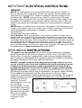
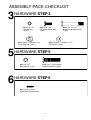
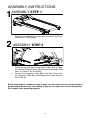
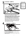
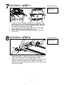
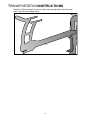
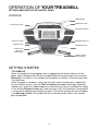
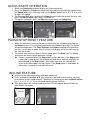
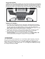
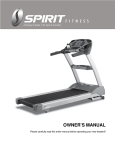
OWNER’S MANUAL PLEASE CAREFULLY READ THIS ENTIRE MANUAL BEFORE OPERATING YOUR NEW TREADMILL! TABLE OF CONTENTS Important Safety Instructions 3 Important Electrical Information 4 Important Operation Instructions 5 Assembly instructions 6 Transport Instructions 12 Operation of Your New Treadmill 13 Programmable Features 17 Using Heart Rate Transmitter 24 General Maintenance 26 Service Checklist - Diagnosis Guide 28 Exploded View Diagram 31 Parts List 32 ST920-YT53_1303(SL)A 2 IMPORTANT SAFETY INSTRUCTIONS WARNING - Read all instructions before using this appliance. DANGER - To reduce the risk of electric shock disconnect your treadmill from the electrical outlet prior to cleaning and/or service work. WARNING - To reduce the risk of burns, fire, electric shock, or injury to persons, install the treadmill on a flat level surface with access to a 220-volt, 10-amp grounded outlet with only the treadmill plugged into the circuit. DO NOT USE AN EXTENSION CORD UNLESS IT IS A 14AWG OR BETTER, WITH ONLY ONE OUTLET ON THE END: DO NOT ATTEMPT TO DISABLE THE GROUNDED PLUG BY USING IMPROPER ADAPTERS, OR IN ANY WAY MODIFY THE CORD SET. A serious shock or fire hazard may result along with computer malfunctions. See Grounding Instructions, page 3. Do not operate treadmill on deeply padded, plush or shag carpet. Damage to both carpet and treadmill may result. Do not block the rear of the treadmill. Provide a minimum of 3 1/2 feet clearance between the rear of the treadmill and any fixed object. Keep children away from the treadmill. There are obvious pinch points and other caution areas that can cause harm. Keep hands away from all moving parts. Never operate the treadmill if it has a damaged cord or plug. If the treadmill is not working properly, call your dealer. Keep the cord away from heated surfaces. Do not operate where aerosol spray products are being used or where oxygen is being administered. Sparks from the motor may ignite a highly gaseous environment. Never drop or insert any object into any openings. Do not use outdoors. To disconnect, turn all controls to the off position, remove tether cord, then remove the plug from the outlet. Do not attempt to use your treadmill for any purpose other than for the purpose it is intended. The pulse sensors are not medical devices. Various factors, including the user’s movement, may affect the accuracy of heart rate readings. The pulse sensors are intended only as exercise aids in determining heart rate trends in general. Use handrails provided; they are for your safety. The pulse sensors are not intended to support the user’s weight. For support when using the treadmill and during dismounting use the side handrails. Wear proper shoes. High heels, dress shoes, sandals or bare feet are not suitable for use on your treadmill. Quality athletic shoes are recommended to avoid leg fatigue. SAVE THESE INSTRUCTIONS - THINK SAFETY! 3 IMPORTANT ELECTRICAL INSTRUCTIONS WARNING! NEVER use a ground fault circuit interrupt (GFCI) wall outlet with this treadmill. As with any appliance with a large motor, the GFCI will trip often. Route the power cord away from any moving part of the treadmill including the elevation mechanism and transport wheels. NEVER remove any cover without first disconnecting AC power. If voltage varies by ten percent (10%) or more, the performance of your treadmill may be affected. Such conditions are not covered under your warranty. If you suspect the voltage is low, contact your local power company or a licensed electrician for proper testing. NEVER expose this treadmill to rain or moisture. This product is NOT designed for use outdoors, near a pool or spa, or in any other high humidity environment. The maximum operating temperature specification is 40 degrees c, and humidity is 95% non-condensing (no water drops forming on surfaces). Circuit Breakers: Some circuit breakers used in exercise facilities or homes are not rated for high inrush currents that can occur when a treadmill is first turned on or even during use. If your treadmill is tripping the facility or home circuit breaker (even though it is the proper current rating) but the circuit breaker on the treadmill itself does not trip, you will need to replace the facility or home breaker with a high inrush type. This is not a warranty defect. This is a condition we as a manufacture have no ability to control. This part is available through most electrical supply stores. Examples: Grainger part # 1D237, or available online at www.squared.com part # QO120HM. GROUNDING INSTRUCTIONS This product must be grounded. If the treadmill should malfunction or breakdown, ground-ing provides a path of least resistance for electric current, reducing the risk of electric shock. This product is equipped with a cord having an equipment-grounding plug. The plug must be plugged into an appropriate outlet that is properly installed and grounded in accordance with all local codes and ordinances. DANGER - Improper connection of the equipment-grounding conductor can result in a risk of electric shock. Check with a qualified electrician or serviceman if you are in doubt as to whether the product is properly grounded. Do not modify the plug provided with the product if it will not fit the outlet; have a proper outlet installed by a qualified electrician. This product is for use on a nominal 220-volt circuit, and has a grounding plug that looks like the plug illustrated below. A temporary adapter that looks like the adapter illustrated below may be used to connect this plug to a 2-pole receptacle as shown below if a properly grounded outlet is not available. The temporary adapter should be used only until a properly grounded outlet, (shown below) can be installed by a qualified electrician. The green colored rigid ear- lug, or the like, extending from the adapter, must be connected to a permanent ground such as a properly grounded outlet box cover. Whenever the adapter is used, it must be held in place by a metal screw. 4 IMPORTANT OPERATION INSTRUCTIONS NEVER operate this treadmill without reading and completely understanding the results of any operational change you request from the computer. Understand that changes in speed and incline do not occur immediately. Set your desired speed on the computer console and release the adjustment key. The computer will obey the command gradually. NEVER use your treadmill during an electrical storm. Surges may occur in your household power supply that could damage treadmill components. Unplug the treadmill during an electrical storm as a precaution. Use caution while participating in other activities while walking on your treadmill; such as watching television, reading, etc. These distractions may cause you to lose balance or stray from walking in the center of the belt; which may result in serious injury. NEVER mount or dismount the treadmill while the belt is moving. Treadmills start at a very low speed and it is unnecessary to straddle the belt during start up. Simply standing on the belt during slow acceleration is proper after you have learned to operate the unit. Always hold on to a handrail or hand bar while making control changes (incline, speed, etc.). Do not use excessive pressure on console control keys. They are precision set to function properly with little finger pressure. Pushing harder is not going to make the unit go faster or slower. If you feel the buttons are not functioning properly with normal pressure contact your dealer. SAFETY TETHER CORD A safety tether cord is provided with this unit. (See Step 6 of Assembly Guide, #63) It is a simple magnetic design that should be used at all times. It is for your safety should you fall or move too far back on the tread-belt. Pulling this safety tether cord will stop tread-belt movement. To Use: 1. Place the magnet into position on the red portion of the console control head. Your tread- mill will not start and operate without this. Removing the magnet also secures the tread- mill from unauthorized use. 2. Fasten the plastic clip onto your clothing securely to assure good holding power. Note: The magnet has strong enough power to minimize accidental, unexpected stop- ping. The clip should be attached securely to make certain it does not come off. Be fa- miliar with its function and limitations. The treadmill will stop, depending on speed, with a one to two step coast anytime the magnet is pulled off the console. Use the red Stop / Pause switch in normal operation. 5 ASSEMBLY PACK CHECKLIST 3 HARDWARE STEP 3 #85. 3/8” x 2T Split Washer (6 pcs) #99. 5/16” x 3/4” Flat Head Socket Bolt (4 pcs) #131. Ø8mm × Ø23mm ×1.5T Curved Washer (4 pcs) 5 6 #102. Ø10mm × Ø19mm × 1.5T Flat Washer (6 pcs) HARDWARE STEP 5 #85. 3/8” x 2T Split Washer (4 pcs) #100. 3/8” x 2-1/4” Button Head Socket Bolt (6 pcs) #125. 3/8” x 1-3/4” Button Head Socket Bolt (4 pcs) HARDWARE STEP 6 #90. 3.5mm x 16mm Sheet Metal Screw (6 pcs) 6 7 HARDWARE STEP 7 #99. 5/16” x 3/4” Flat Head Socket Bolt (4 pcs) 8 HARDWARE STEP 8 #126. M5 x 10mm Phillips Head Screw (4 pcs) ASSEMBLY TOOLS 104. Combination M5 Allen Wrench & Phillips Head Screw Driver #105. M6 L Allen Wrench 7 ASSEMBLY INSTRUCTIONS 1 ASSEMBLY STEP 1 1. 2 1. 2. Remove the treadmill base frame from the carton and lay it aside on firm, level ground. ASSEMBLY STEP 2 Locate the left and right Console Mast Tubes (5 & 4). Slide the Handrail Bottom Cover (118) onto the left and right (120) tubes as shown in the illustration. Connect the Computer Cable (32) of the Main Frame with the Computer Cable (33) at the bottom of the right Console Mast Tube (4). Before attaching the hardware to Step 3, make sure the cables you just connected don’t get pinched in between the steel tubing. If they do, this may cause issues that prevent the treadmill from operating properly. 8 3 ASSEMBLY STEP 3 HARDWARE STEP 3 #85. 3/8” x 2T Split Washer (6 pcs) #99. 5/16” x 3/4” Flat Head Socket Bolt (4 pcs) #100. 3/8”x 2-1/4” Button Head Socket Bolt (6 pcs) #102. Ø10mm × Ø19mm × 1.5T Flat Washer (6 pcs) #131. Ø8mm × Ø23mm × 1.5T Curved Washer (4 pcs) 1. Attach the left and right Upright Tubes (5 & 4) to the Main Frame (1). Be careful installing the right upright so that the wire harness doesn’t get pinched or cut. Only hand-tighten all the bolts in this step. The bolts will need to be completely tightened after the console is installed. Insert three Split Washers (85), three Flat Washers (102), and three Button Head Socket Bolts (100) through the brackets (151 & 152) and Console Mast Tubes (5 & 4) and into the frame. Partially tighten with the M6 L Allen Wrench (105). Attach two Curved Washers (131) and two Flat Head Socket Bolts (99) to the front of each Console Mast Tube. Partially tighten with the M5 Combination Allen Wrench & Phillips Head Screw Driver (104). 4 ASSEMBLY STEP 4 1. Connect the Speed Adjustment Switch W/Cable (34) with the Speed Cable (Upper)( 36-33). 2. Connect the Incline Adjustment Switch W/Cable (35) with the Incline Cable (Upper)( 36-34). 3. Connect the Computer Cable (33) with the Computer Cable (Upper/Lower) (31). 9 Before attaching the hardware in Step 5, make sure the cables you just connected don’t get pinched in between the steel tubing. If they do, this may cause issues that prevent the treadmill from operating properly. 5 ASSEMBLY STEP 5 #85. 3/8” x 2T Split Washer (4 pcs) #125. 3/8”x 1-3/4” Button Head Socket Bolt (4 pcs) 1. 6 HARDWARE STEP 5 Carefully attach the Console Assembly (36) to the top of the upright tubes(5 & 4) with the four Button Head Socket bolts (125) and four Split Washers(85). Make sure the cables don’t get pinched between the joint or by the bolts. Tighten the bolts completely using the M6 Allen Wrench (105). ASSEMBLY STEP 6 HARDWARE STEP 6 #90. 3.5mm x 16mm Sheet Metal Screws (6 pcs) 1. Attach the two halves of each Handrail Cover (117 & 118; 119 & 120) with three Sheet Metal Screws (90) on each set of plastics. 10 7 ASSEMBLY STEP 7 HARDWARE STEP 7 #99. 5/16” x 3/4” Flat Head Socket Bolt (4 pcs) 1. 2. 3. Install the Handrail Support (3) between the Upright Tubes (5 & 4) with the four Flat Head Socket bolts (99). Tighten the bolts completely using the Com- bination M5 Allen Wrench and Phillips Head Screw Driver (104). After affixing the end tabs (146 & 147), slip the Beverage Holder (48) over the Handrail Support (3). Make sure the magnet of the Safety Key (63) is affixed to the console. 8 ASSEMBLY STEP 8 HARDWARE STEP 8 #126. M5 x 10mm Phillips Head Screw (4 pcs) 1. 2. Completely tighten the bolts that secure the Console Mast Tubes to the frame with the M6 Allen Wrench (105). Attach the console mast covers (40R & 41L) to each mast (5 & 4) with two Phillips Head Screws (126) on each side. Tighten using the Combination Allen Wrench & Phillips Head Screw Driver (104). 11 TRANSPORTATION INSTRUCTIONS Carefully lift the treadmill at the rear roller area, grasping the two side end caps, and roll the treadmill away. 12 OPERATION OF YOUR TREADMILL GETTING FAMILIAR WITH THE CONTROL PANEL CONSOLE COOLING FANS SPEED QUICK KEYS INCLINE QUICK KEYS FAN POWER SWITCH DISPLAY BUTTON DOT MATRIX DISPLAY CONTROL KEYS HEADPHONE JACK AUDIO IN JACK (MP3, CD, or SMARTPHONE) CONTACT HEART RATE SENSORS GETTING STARTED TT8 CONSOLE Power the treadmill on by plugging it into an appropriate wall outlet, then turn on the power switch located at the front of the treadmill below the motor hood. Ensure that the Safety Key is installed, as the treadmill will not power on without it (See Assembly Step 7 for reference). When the power is turned on, a message will scroll across the dot matrix showing the current software version. Then the Time and Distance windows will display Odometer readings for a short time, Time window will show how many hours the treadmill has been in use and the Distance window will show how many miles (or Kilometers if the treadmill is set to metric readings) the treadmill has gone. The current software version will appear in the Message window. The treadmill will then enter idle mode, which is the starting point for operation. 13 QUICK-START OPERATION 1. Attach the Safety Key to wake display up (if not already on). 2. Press the Start key to begin belt movement then adjust to the desired speed using the Speed ▲/▼ keys. You may also use the Quick speed keys 2, 3, 4, 5, 6, 9, or 12 to adjust the speed. 3. To slow tread-belt, press and hold the Slow key to the desired speed. You may also press the Quick speed adjust keys, 2 through 12. 4. To stop the tread-belt, press the Stop key or pull away the Safety Key. PAUSE/STOP/RESET FEATURE 1. When the treadmill is running the pause feature may be utilized by pressing the red Stop key once. This will slowly decelerate the tread-belt to a stop. The incline will go to zero percent. The Time, Distance and Calorie readings will hold while the unit is in the pause mode. After 5 minutes the display will reset and return to the start up screen. 2. To resume your exercise, when in Pause mode, press the Start key. The speed and incline will return to their previous settings. Pause is executed when the Stop button is pressed once. If the Stop button is pressed a second time, the program will end and a workout summary will be displayed. If the Stop button is pressed a third time, the console will return to the idle mode (start up) screen. If the Stop button is held down for more than 3 seconds the console will reset. INCLINE FEATURE Incline may be adjusted anytime after belt movement. Press and hold the Incline ▲/▼ keys to achieve desired level of incline. You may also choose a more rapid increase / decrease by selecting the desired Quick Incline key, 1, 3, 6, 9, 12, 14, 15, on left hand side of console (incline). The space above the Incline heading on the LCD will indicate deck elevation as adjustments are made. 14 DOT MATRIX CENTER DISPLAY Twenty columns of dots (10 high) indicate each segment (speed or incline) of a workout. They do not necessarily indicate a specific value - only an approximate percent to compare levels of intensity. In Manual Operation the Speed / Incline dot matrix window will build a profile “picture” as values are changed during a workout. The 20 columns are divided into 1/20th of the total time of the program. The Dot Matrix window will show the left half of the speed and incline profiles. Once the program begins, the profiles will scroll right to left. You may change the Dot Matrix profile view by pressing the Enter button. After scrolling through the two profiles the Dot Matrix will automatically scroll through the two displays showing each one for five seconds. The icon associated with each profile will light while that view is displayed. Pressing the Enter button a third time will alternate the display view between the Speed and Incline profiles. MESSAGE WINDOW DISPLAY The Message Window will initially display Program Name. Each time the Display button is pressed the next set of information will appear. The order of information displayed will be: Laps, Vertical, MET’s, Segment Time, Max Speed (in mph), and Data Scan mode. In Data Scan mode, the displayed information will change every 4 seconds in the Message Window. 1/4 MILE TRACK The 1/4-Mile Track (0.4 km) will be displayed around the Speed and Incline profiles. The flashing dot indicates your progress and will advance in a counterclockwise direction. CALORIE DISPLAY Displays the cumulative calories burned at any given time during your workout. Note: This is only a rough guide used for comparison of different exercise sessions, which cannot be used for medical purposes. There is an Audio Input Jack ( ) on the front of the console and built-in speakers. You may plug any low-level audio source signal into this port. Audio sources include MP3, iPod, portable radio, CD player or even a TV or computer audio signal. There is an audio patch cable included to and also a headphone jack ( ) for private listening. 15 PULSE GRIP FEATURE The Pulse (Heart Rate) window will display your current heart rate in beats per minute during the workout. You must use both left and right stainless steel sensors on the front cross bar to pick up your pulse. Pulse values are displayed anytime the computer is receiving a Grip Pulse signal or while wearing an optional chest strap transmitter (see Using the Heart Rate Transmitter section for directions). You may use the Grip Pulse feature while in a Heart Rate Program (HR1 or HR2). TURNING OFF TREADMILL 1. The display will automatically turn off – go to sleep - after 30 minutes of inactivity when in the Pause / Stop mode. Almost all power for the treadmill will be off except for some circuits that are needed to detect if any key is pressed, indicating the console should “wake up”. When the console is “asleep” the treadmill draws very little power, about as much as your television when it is turned off. 2. Removing the safety key is similar to entering “sleep” mode. Turning off the main power switch in the front of the treadmill will completely remove any power. 3. To exit the display mode, for normal operation, press and hold the Stop/Enter/Display keys for 5 seconds; the display will show Display Mode - ON. Use the speed Up key to change the setting to OFF then press Enter. **ATTENTION** Your new console comes configured in an in-store ‘display mode’ of operation, where the console will remain powered on unless the main power switch is turned off. To exit the display mode, for normal operation, press and hold the Stop, Enter and Display keys for 5 seconds; the display will show: Display mode - On. Use the Up arrow or Fast key to change the setting to Off then press Enter. 16 PROGRAMMABLE FEATURES The TT8 has ten built-in programs: one Manual program, five preset profiles, one Custom, one Fit Test, and two Heart Rate programs (HR1 & HR2). PRESET PROGRAMS Hill The Hill program simulates going up and down a hill. The speed will steadily increase and then decrease during the program. SPEED INCLINE Fat Burn The Fat Burn program is designed, as the name implies, to maximize the burning of fat. There are many schools of thought on the best way to burn fat but most experts agree that a lower exertion level that stays at a steady workload is the best. The absolute best way to burn fat is to keep your heart rate at around 60% to 70% of its maximum potential. This program does not use heart rate but simulates a lower, steady exertion workout. SPEED INCLINE Cardio The Cardio program is designed to increase your cardiovascular function and endurance. This is exercise for your heart and lungs. It will build up your heart muscle and increase blood flow and lung capacity. This is achieved by incorporating a higher level of exertion with slight fluctuations in work. SPEED INCLINE Strength The Strength program is designed to increase muscular strength in your lower body. This program will steadily increase in speed to a high level and forces you to sustain it. This is designed to strengthen and tone your legs and glutes (muscles of the butt). SPEED INCLINE Interval The Interval program takes you through high levels of intensity followed by periods of low intensity. This program increases your endurance by depleting your oxygen level followed by periods of recovery to replenish oxygen. Your cardiovascular system gets programmed to use oxygen more efficiently this way. This program also forces your body to become more efficient due to spikes in heart rate, between recovery periods. This aids in heart rate recovery from intense activities. SPEED INCLINE 17 SELECTING A PROGRAM 1. Press the desired program from the 10 available program keys. Then press the Enter key to begin customizing the program with your personal data, or just press the Start key to begin the program with the default settings. 2. 3. The Message window will now be showing a value, indicating your Age. Entering your correct age affects the heart rate Bar Graph Display and the Heart Rate programs. Use the Up/Down keys to adjust, and then press Enter. Your age determines the maximum heart rate you may achieve. Since the Bar Graph Display and the Heart Rate features are based on a percentage of your maximum heart rate, it is important to enter the correct age for these features to work properly. The Message window will now be showing a value, indicating your Body Weight. Entering the correct body weight will affect the Calorie count. Use the Up/Down keys to adjust, and then press Enter. * A note about the Calorie display: No exercise machine can give you an exact calorie count because there are too many factors which determine exact calorie burn for a particular person. Even if someone is the exact same body weight, age and height, their calorie burn may be very different than yours. The Calorie display is to be used as a reference only to monitor improvement from workout to workout. 4. 5. 6. After selecting a program and pressing Enter to set your personal data, the Time window will show the default value of 20 minutes. Use the Up/Down keys to adjust, then press Enter. The Message window will now be blinking, showing the preset top speed of the selected pro- gram. Use the Up/Down keys to adjust, and then press Enter. Each program has various speed changes throughout; this allows you to limit the highest speed the program will attain during your workout. Press Start to begin or Enter to modify your settings. 18 CUSTOM PROGRAM 1. Select Custom on the Program keypad, then press Enter. Note that the dot matrix display portion will light a single row of dots at the bottom (Unless there is a previously saved program). If there is a program stored under the button that is pressed, it will be retrieved. If not, you have the option of programming in your first name. The Message window will display and flash the letter ”A” . To change it, press the arrow key, then “B” will be displayed; if the arrow key is pressed, the letter “Z” will be displayed. After selecting the appropriate letter, press Enter. The letter “A” will again be displayed and blinking. Repeat the procedure until all letters of your first name are programmed (7 characters maximum). When your name is displayed, press Stop and it will be stored under Custom. 2. The Message window will now show an Age value. Adjust the age with the Up/Down keys and press Enter. 3. The Message window will show a bodyweight value. Adjust the number with the Up/Down keys to your bodyweight value and press Enter. 4. The Time window will be flashing. Use the Up/Down adjustment keys to set the program for the desired time. Press the Enter key. This is a must to continue even if the time is not adjusted. 5. 5. The first speed setting column (segment) will now be blinking. Using the Fast/Slow keys, adjust the speed to your desired effort level for the first segment then press Enter. The second column will now be blinking. Note that the previous segment value has been carried over to the new segment. Repeat the above process until all speed segments have been programmed. Note: While in a User program, if you manually change the speed, all segment speeds from there on will also change. Examples: If you increase your current speed 1 mph, the remaining segment speeds will increase by 1 mph. If you decrease your current speed .5 mph, the remaining segment speeds will decrease by .5 mph, etc. 6. 7. The first column will be blinking again. The console is now ready for the incline settings. Repeat the same process used to set the speed values for programming the segments for incline. Press the Start button to begin the workout and also save the program to memory. 19 Fit Test Program The fit test program is designed to determine your estimated VO2 max or how well your body utilizes oxy- gen. The test follows a progression in both speed and elevation and lasts a maximum of 11 minutes. If your actual heart rate reaches 85% of projected maximum before the end of the test, the program will end and your score will be based on the stage you ended at. The higher your estimated VO2, the more fit you are. 1. 2. 3. 4. 5. 6. 6. 7. When the Fit Test button is pressed, the Message Window will display GERKIN PROTOCOL PRESS ENTER TO BEGIN The Message Window will now be showing a value, indicating your Age. Use the Up/Down keys to adjust, and then press Enter. The Message Window will now be showing a value, indicating your Body Weight. Use the Up/Down keys to adjust, and then press Enter. The Message Window will display PRESS START TO BEGIN OR ENTER TO MODIFY The test starts with a three minute warm-up. Speed will be set at 3 mph, grade at 0%. The Message Window will display 3 MINUTE WARM-UP And alternate every 5 seconds with actual HR 888 & Target Heart Rate. The time window will start at three minutes and count down to zero. All other data windows will accrue. Stage 1 2.1 2.2 2.3 2.4 3.1 3.2 3.3 3.4 4.1 4.2 4.3 4.4 5.1 5.2 5.3 5.4 6.1 6.2 6.3 6.4 7.1 7.2 7.3 7.4 8.1 8.2 8.3 8.4 9.1 9.2 9.3 9.4 10.1 10.2 10.3 10.4 11.1 11.2 11.3 11.4 Time 0 to 1:00 1:15 1:30 1:45 2:00 2:15 2:30 2:45 3:00 3:15 3:30 3:45 4:00 4:15 4:30 4:45 5:00 5:15 5:30 5:45 6:00 6:15 6:30 6:45 7:00 7:15 7:30 7:45 8:00 8:15 8:30 8:45 9:00 9:15 9:30 9:45 10:00 10:15 10:30 10:45 11:00 Speed 7.2 kph 7.2 kph 7.2 kph 7.2 kph 7.2 kph 8.0 kph 8.0 kph 8.0 kph 8.0 kph 8.0 kph 8.0 kph 8.0 kph 8.0 kph 8.8 kph 8.8 kph 8.8 kph 8.8 kph 8.8 kph 8.8 kph 8.8 kph 8.8 kph 9.6 kph 9.6 kph 9.6 kph 9.6 kph 9.6 kph 9.6 kph 9.6 kph 9.6 kph 10.4 kph 10.4 kph 10.4 kph 10.4 kph 10.4 kph 10.4 kph 10.4 kph 10.4 kph 11.2 kph 11.2 kph 11.2 kph 11.2 kph Grade 0% 2% 2% 2% 2% 2% 2% 2% 2% 4% 4% 4% 4% 4% 4% 4% 4% 6% 6% 6% 6% 6% 6% 6% 6% 8% 8% 8% 8% 8% 8% 8% 8% 10% 10% 10% 10% 10% 10% 10% 10% VO2 Max 31.15 32.55 33.6 34.65 35.35 37.45 39.55 41.3 43.4 44.1 45.15 46.2 46.5 48.6 50 51.4 52.8 53.9 54.9 56 57 57.7 58.8 60.2 61.2 62.3 63.3 64 65 66.5 68.2 69 70.7 72.1 73.1 73.8 74.9 76.3 77.7 79.1 80 The speed and incline will follow the changes shown in the chart to the right. When the user reaches the target the test will continue for 15 seconds. A cool down period will start. The incline will be set to 0 percent. The speed will be 4.8 KPH. The cool down time will be based on the total time to complete the test. If the test took 5 min. or less, then the cool down is 1 minute. If the test took between 5 min. to 12 min., the cool down will be 3 minutes. The Message Window will display for 5 seconds: 1 (or 3 min) MIN COOL DOWN and alternate every 5 seconds with YOUR SCORE. The time window will start at 1 (or 3 min) minute and count down to zero. 20 8. The score is taken from the table based on the final stage completed. After the cool down the Message Window will display TEST OVER PRESS STOP TO END OR ENTER TO SEE SCORE. If no button is pressed for 20 seconds, the screen goes to the idle mode. If Enter is pressed, the score will be displayed for 10 seconds then go to TEST OVER…. Message. What your score means: VO2max Chart for males and very fit females excellent good above average average below average poor very poor 18-25 years old >60 52-60 47-51 26-35 years old >56 49-56 43-48 36-45 years old >51 43-51 39-42 46-55 years old >45 39-45 35-38 56-65 years old >41 36-41 32-35 65+ years old >37 33-37 29-32 42-46 37-41 40-42 35-39 35-38 31-34 32-35 29-31 30-31 26-29 26-28 22-25 30-36 <30 30-34 <30 26-30 <26 25-28 <25 22-25 <22 20-21 <20 56-65 years old 37 32-37 28-31 65+ years old 32 28-32 25-27 25-27 22-24 22-24 19-22 18-21 <18 17-18 <17 VO2max Chart for females and de-conditioned males 18-25 26-35 36-45 46-55 years years years years old old old old excellent 56 52 45 40 good 47-56 45-52 38-45 34-40 above 42-46 39-44 34-37 31-33 average average 38-41 35-38 31-33 28-30 below 33-37 31-34 27-30 25-27 average poor 28-32 26-30 22-26 20-24 very <28 <26 <22 <20 poor 21 HEART RATE PROGRAMS Before we get started, a word about Heart Rate: The old motto, “no pain, no gain”, is a myth that has been overpowered by the benefits of exercising comfortably. A great deal of this success has been promoted by the use of heart rate monitors. With the proper use of a heart rate monitor, many people find that their usual choice of exercise intensity was either too high or too low and exercise is much more enjoyable by maintaining their heart rate in the desired benefit range. To determine the benefit range in which you wish to train, you must first determine your Maximum Heart Rate. This can be accomplished by using the following formula: 220 minus your age. This will give you the Maximum Heart Rate (MHR)for someone of your age. To determine the effective heart rate range for specific goals you simply calculate a percentage your MHR. Your Heart rate training zone is 50% to 90% of your maximum heart rate. 60% of your MHR is the zone that burns fat while 80% is for strengthening the cardio vascular system. This 60% to 80% is the zone to stay in for maximum benefit. For someone who is 40 years old their target heart rate zone is calculated: 220 – 40 = 180 (maximum heart rate) 180 x .6 = 108 beats per minute (60% of maximum) 180 X .8 = 144 beats per minute (80% of maximum) So for a 40 year old the training zone would be 108 to 144 beats per minute. If you enter your age during programming the console will perform this calculation automatically. Entering your age is used for the Heart Rate programs. After calculating your MHR you can decide upon which goal you would like to pursue. The two most popular reasons for, or goals, of exercise are cardiovascular fitness (training for the heart and lungs) and weight control. The black columns on the chart above represent the MHR for a person whose age is listed at the bottom of each column. The training heart rate, for either cardiovascular fitness or weight loss, is represented by two different lines that cut diagonally through the chart. A definition of the lines’ goal is in the bottom left-hand corner of the chart. If your goal is cardiovascular fitness or if it is weight loss, it can be achieved by training at 80% or 60%, respectively, of your MHR on a schedule approved by your physician. Consult your physician before participating in any exercise program. 22 RATE OF PERCEIVED EXERTION Heart rate is important but listening to your body also has a lot of advantages. There are more variables involved in how hard you should workout than just heart rate. Your stress level, physical health, emotional health, temperature, humidity, the time of day, the last time you ate and what you ate, all contribute to the intensity at which you should workout. If you listen to your body, it will tell you all of these things. The rate of perceived exertion (RPE), also know as the Borg scale, was developed by Swedish physiologist G.A.V. Borg. This scale rates exercise intensity from 6 to 20 depending upon how you feel or the perception of your effort. The scale is as follows: Rating Perception of Effort 6 Minimal 7 Very, very light 8 Very, very light + 9 Very light 10 Very light + 11 Fairly light 12 Comfortable 13 Somewhat hard 14 Somewhat hard + 15 Hard 16 Hard + 17 Very hard 18 Very hard + 19 Very, very hard 20 Maximal You can get an approximate heart rate level for each rating by simply adding a zero to each rating. For example a rating of 12 will result in an approximate heart rate of 120 beats per minute. Your RPE will vary depending up the factors discussed earlier. That is the major benefit of this type of training. If your body is strong and rested, you will feel strong and your pace will feel easier. When your body is in this condition, you are able to train harder and the RPE will support this. If you are feeling tired and sluggish, it is because your body needs a break. In this condition, your pace will feel harder. Again, this will show up in your RPE and you will train at the proper level for that day. 23 USING HEART RATE TRANSMITTER (Optional) How to wear your wireless chest strap transmitter: 1. Attach the transmitter to the elastic strap using the locking parts. 2. Adjust the strap as tightly as possible as long as the strap is not too tight to remain comfortable. 3. Position the transmitter with the centered in the middle of your body facing away from your chest (some people must position the transmitter slightly left of center). Attach the final end of the elastic strap by inserting the round end and, using the locking parts, secure the transmitter and strap around your chest. 4. Position the transmitter immediately below the pectoral muscles. 5. Sweat is the best conductor to measure very minute heart beat electrical signals. However, plain water can also be used to pre-wet the electrodes (2 ribbed oval areas on the reverse side of the belt and both sides of the transmitter). It’s also recommended that you wear the transmitter strap a few minutes before your work out. Some users, because of body chemistry, have a more difficult time in achieving a strong, steady signal at the beginning. After “warming up”, this problem lessens. As noted, wearing clothing over the transmitter/strap doesn’t affect performance. 6. Your workout must be within range - distance between transmitter/receiver – to achieve a strong steady signal. The length of range may vary somewhat but generally stay close enough to the console to maintain good, strong, reliable readings. Wearing the transmitter immediately against bare skin assures you of proper operation. If you wish, you may wear the transmitter over a shirt. To do so, moisten the areas of the shirt that the electrodes will rest upon. Note: The transmitter is automatically activated when it detects activity from the user’s heart. Additionally, it automatically deactivates when it does not receive any activity. Although the transmitter is water resistant, moisture can have the effect of creating false signals, so you should take precautions to completely dry the transmitter after use to prolong battery life (estimated transmitter battery life is 2500 hours). The replacement battery is Panasonic CR2032. ERRATIC OPERATION Caution! Do not use this treadmill for Heart Rate unless a steady, solid Actual Heart Rate value is being displayed. High, wild, random numbers being displayed indicate a problem. Areas to look for interference which may cause erratic heart rate: 1. 2. 3. 4. 5. Microwave ovens, TV’s, small appliances, etc. Fluorescent lights. Some household security systems. Perimeter fence for a pet. Some people have problems with the transmitter picking up a signal from their skin. If you have problems try wearing the transmitter upside down. Normally the transmitter will be oriented so the is right side up. 6. The antenna that picks up your heart rate is very sensitive. If there is an outside noise source, turning the whole machine 90 degrees may de-tune the interference. 7. Loose treadmill console or bolts in the upright tube. 8. Another Individual wearing a transmitter within 3’ of your machine’s console. If you continue to experience problems contact your dealer. WARNING! - DO NOT USE THE HEART RATE PROGRAM IF YOUR HEART RATE IS NOT REGISTERING PROPERLY ON THE TREADMILL’S DISPLAY! 24 HEART RATE PROGRAMMING CAUTION! You may use either the pulse grip sensors or a wireless heart rate chest strap (sold separately) for either heart rate program. You must receive a strong/steady value in the heart rate window (See Using Heart Rate Transmitter section for instructions on how to use). The HR1 program has a default level that is 60% of your projected heart rate maximum. This program is geared for individuals with fat loss as a goal. The HR2 program has a default of 80% of your projected heart rate maximum. It is geared for individuals with a goal of improving cardiovascular & lung function. 1. Select HR1 or HR2 via the Program keys then press Enter. 2. The Message window will now be blinking showing user’s age. Adjust and press Enter or press Enter to accept the default value. Adjusting Age will change the Target HR value. 3. The Message window will be blinking, showing the default user’s bodyweight for this program. You may adjust it and press Enter if you want or just press Enter to accept the default value. 4. Now you are asked to adjust the HR1 or HR2 value. The default is 60% (HR1); (220 age x.60); or 80% (HR2); (220 – age x .80). You may select a higher or lower number also. Adjust the number by pressing the Speed Up or Down keys and press Enter to continue. 5. The Time window will now be blinking. Adjust the time and press Enter. 6. Now you are finished editing the settings and can begin your workout by pressing the Start key. You can also go back and modify your settings by pressing the Stop key to go back one level, or screen. 7. If you want to increase or decrease the speed at any time during the program press the Fast or Slow keys. 8. During the HR program you will be able to scroll through the data in the message window by pressing the Display key. When the program ends the message window will show a summary of your workout. The summary will be displayed for a short time then the console will return to the start-up display. 9. Press Start to begin program. The program will now control the treadmill Incline to steadily increase your heart rate to the target value. This process is automatic and could take upwards of five minutes, depending on how far your HR needs to go and what kind of physical shape you are in. People who are more fit will take longer to reach the target. You can make manual adjustments to the speed throughout the program. The message window will give you prompts on reducing or increasing speed, depending on where your heart rate is in relation to the selected heart rate %. 25 GENERAL MAINTENANCE BELT & DECK Your treadmill uses a very high-efficient low-friction deck. Performance is maximized when the deck is kept as clean as possible. Use a soft, damp cloth, or paper towel, wipe the edge of the belt and the area between the belt edge and the frame. Also reach as far as practical directly under the belt edge. This should be done once a month to extend belt and bed life. A mild soap and water solution along with a nylon scrub brush will clean the top of the textured belt. Allow to dry before using. BELT DUST This occurs during normal break-in or until the belt stabilizes. Sometimes the black dust from the belt will appear on the floor behind the treadmill, this is normal. GENERAL CLEANING (Use the chart on Pg. 5 to record your maintenance) Dirt, dust, and hair can block air inlets and accumulate on the running belt. Please vacuum underneath your treadmill on a monthly basis to prevent excess build-up of dirt that can get sucked up and get into the inner workings under the motor cover. Every other month, you should remove the motor cover and carefully vacuum out dirt and hair that may accumulate. UNPLUG THE POWER CORD BEFORE THIS TASK. BELT ADJUSTMENTS Tread-belt Tension Adjustment - Belt tension is not critical for most users. It is very important though for joggers and runners in order to provide a smooth, steady running surface. Adjustment must be made from the rear roller with the M6 L Allen wrench (105) provided in the parts package. The adjustment bolts are located at the end of the step rails as shown in the diagram below. Note: Adjustment is through small hole in end cap. Tighten the rear roller only enough to Note: Adjustment is through small hole in end prevent slippage at the front roller. Turn the cap. tread-belt tension adjusting bolts 1/4 turn each and inspect for proper tension by walking on the belt and making sure it is not slipping or hesitating with each step. When an adjustment is made to the belt tension, you must be sure to turn the bolts on both sides evenly or the belt could start tracking to one side instead of running in the middle of the deck. DO NOT OVERTIGHTEN – Over tightening will cause belt damage and premature bearing failure. If you tighten the belt a lot and it still slips, the problem could actually be the drive belt- located under the motor cover - that connects the motor to the front roller. If that belt is loose it feels similar to the walking belt being loose. Tightening the motor belt should be done by a trained service person. 26 TREAD-BELT TRACKING ADJUSTMENT The treadmill is designed so that the tread-belt remains reasonably centered while in use. It is normal for some belts to drift near one side while in use, depending on a user’s gait and if they favor one leg. But if during use the belt continues to move toward one side, adjustments are necessary. SETTING TREAD-BELT TRACKING A 6 mm Allen wrench (105) is provided for this adjustment. Make tracking adjustments on the left side bolt. Set belt speed at 3 mph. Be aware that a small adjustment can make a dramatic difference which may not be apparent right away. If the belt is too close to the left side, then turn the bolt only a 1/4 turn to the right (clockwise) and wait a few minutes for the belt to adjust itself. Continue to make 1/4 turns until the belt stabilizes in the center of the running deck. If the belt is too close to the right side, turn the bolt counter-clockwise. The belt may require periodic tracking adjustment depending on use and walking/running characteristics. Some users may affect tracking differently. Expect to make adjustments as required to center the tread-belt. Adjustments will become less of a maintenance concern as the belt is used. Proper belt tracking is an owner responsibility common with all treadmills. ATTENTION: DAMAGE TO THE RUNNING BELT RESULTING FROM IMPROPER TRACKING / TENSION ADJUSTMENTS IS NOT COVERED UNDER THE SOLE WARRANTY. TREADMILL BELT The walking belt on your new treadmill is made of the highest quality materials designed to last even under punishing conditions. When a treadmill belt is brand new, and has been in the package for a few months before use, a common occurrence can happen; the area of the belt that wraps around the rollers will take on the shape of the roller. Upon starting the treadmill this shape in the belt causes a thumping sound each time the belt moves past the rollers. Once the treadmill has been used for a few workouts, the belt wears in and the thumping sound goes away. This noise is normal on new higher end belts so there is no need to contact service; the new belt just requires a wear in period. Thank you for choosing and enjoy your new treadmill. 27 SERVICE CHECKLIST - DIAGNOSIS GUIDE Before contacting your dealer for aid, please review the following information. It may save you both time and expense. This list includes common problems that may not be covered under the treadmill’s warranty. PROBLEM SOLUTION/CAUSE Display does not light 1. Tether cord not in position. 2. Circuit breaker on front grill tripped. Push circuit breaker in until it locks. 3. Plug is disconnected. Make sure plug is firmly pushed into AC household wall outlet. 4. Household circuit breaker may be tripped. 5. Treadmill defect. Contact your dealer. Tread-belt does not stay centered Treadmill belt hesitates when walked/run on The user may be walking while favoring or putting more weight on either the left or right foot. If this walking pattern is natural, track the belt slightly off-center to the side opposite from the belt movement. See General Maintenance section on Tread-belt Tension. Adjust as necessary. Motor is not responsive after pressing Start 1. If the belt moves, but stops after a short time and the display shows “LS”, run calibration. 2. If you press Start and the belt never moves, then the display shows LS, contact service. Treadmill will only achieve approximately 7 mph but shows higher speed on display This indicates motor should be receiving power to operate. Low AC voltage to treadmill. Do not use an extension cord. If an extension cord is required it should be as short as possible and heavy duty 16 gauge minimum. Low household voltage. Contact an electrician or your dealer. A minimum of 220 volt AC is required. Tread-belt stops quickly/suddenly when tether cord is pulled High belt/deck friction. See General Maintenance section on lubrication. Treadmill trips on board 10 amp circuit High belt/deck friction. See General Maintenance Computer shuts off when console is touched (on a cold day) while walking/running Treadmill may not be grounded. Static electricity is “crashing” the computer. Refer to Grounding Instructions on page 3. House circuit breaker trips, but not the treadmill circuit breaker Need to replace the house breaker with a “High In-rush current” type breaker (see page 3 for detail tails) 28 CALIBRATION PROCEDURE 1. Remove the Safety Key. 2. Press and hold down the Start and Speed ▲ buttons and replace the Safety Key. Continue to hold the Start and Speed ▲ key until the window displays “Factory settings”, then press the Enter key. 3. You will now be able to set the display to show Metric or English settings (Miles vs. Kilometers). To do this, press the Incline ▲/▼key to show which you want, then press Enter. 4. Make sure the wheel size diameter is 3.01 then press Enter. 5. Adjust the minimum speed (if needed) to 1.0 and then press Enter. 6. Adjust the maximum speed (if needed) to 18.0 and then press Enter. 7. Adjust the maximum elevation (if needed) to 15 and then press Enter. 8. Grade return – On (This allows the incline to return to zero when Stop is pressed. For sale in Europe, EU standards require this to be off ). 9. Press Start to begin calibration. The process is automatic; the speed will start up without warning, so do not stand on the belt. ADJUSTING THE SPEED SENSOR If the calibration does not pass you may need to check the speed sensor alignment. 1. Remove the motor cover hood by loosening the 4 screws that hold it in place (you do not need to remove them completely). 2. The speed sensor is located on the left side of the frame, right next to the front roller pulley (the pulley will have a belt around it that also goes to the motor). The speed sensor is small and black with a wire connected to it. 3. Make sure the sensor is as close as possible to the pulley without touching it. You will see a magnet on the face of the pulley; make sure the sensor is aligned with the magnet. There is a screw that holds the sensor in place that needs to be loosened to adjust the sensor. Re-tighten the screw when finished. MAINTENANCE MENU 1. Press and hold the Start, Stop and Enter key at the same time and install safety key, until the display shows “Engineering Mode” (it may say maintenance menu, depending on version). Press the Enter key. 2. You can now scroll through the menu using the Speed ▲/▼keys. Use the Stop key to return to previous menu selection. The menu selections are: A. Key Test - Will allow you to test all the keys to make sure they are functioning B. Display Test - Tests all the display functions C. Functions - Press Enter to access settings, use Speed ▲/▼ keys to scroll I. Display Mode - Turn off to have the console power down automatically after 30 minutes of inactivity II. Pause Mode - Turned on to allow 5 minutes of pause, turn off to have console pause in definitely III. Maintenance - Reset lube message and odometer readings IV. Units - Choose from English or Metric display readings V. Key Tone - Will turn on/off beeping noise that is made when keys are pressed. D. Security - Allows you to lock the keypad so no unauthorized use of the machine is allowed. When the child lock is enabled, the console will not allow the keypad to operate unless you press and hold the Start and Enter buttons for 3 seconds to unlock the console. E. Exit 30 EXPLODED VIEW DIAGRAM 31 PARTS LIST Part Number Part Description 1 Main Frame 2 Incline Bracket 3 Handrail Support 4 Right Upright 5 Left Upright 6 Console Support 7 Deck Cross Brace 9 Drive Belt 10 W/Pulley 10~3 Magnet 11 Rear Roller 12 Running Deck 13 Running Belt 14 PVC Handgrip 17 Clevis Pin Bracket 19 Safety Key Sleeve 20 Drive Motor 21 Incline Motor 22~1 Motor Controller 22~2 Adaptor 23 1200m/m_Sensor W/Cable 24 Breaker 25 Power Socket 26 On/Off Switch 27 Power Cord 28 70m/m_Connecting Wire (Black) 29 350m/m_Connecting Wire (White) 30 350m/m_Connecting Wire (Black) 31 700m/m_Computer Cable (Upper/Lower) 32 550m/m_Computer Cable (Upper/Lower) 33 1200m/m_Computer Cable 34 300m/m_Speed Handgrip Switch W/Assembly 35 300m/m_Incline Handgrip Switch W/Assembly 36 Console Assembly 36-1 Console Top Cover 36-2 Console Bottom Cover 36-3 INCLINE Key(L) 36-4 SPEED Key(R) 36-5 Drink Bottle Holder (L) 36-6 Drink Bottle Holder (R) 36-7 Lower Controller Button–TPR 36-8 Button Frame 36~9 Stop Key 36~10 Start Key 36~11 Square Magnet Stop Plate 36~12 Console Display Board 36-17 Front Console Cover (Top) 36-18 Front Console Cover (Bottom) 32 Qty per unit 1 1 1 1 1 1 1 1 1 2 1 1 1 2 8 1 1 1 1 1 1 1 1 1 1 1 1 1 1 1 1 1 1 1 1 1 1 1 1 1 1 1 1 1 2 1 1 1 Part Number Part Description 36-19 300m/m_Safety Switch Module W/ Cable 36-20 Fan Assembly(Optional) 36-21 Deflector Fan Grill 36-22 Fan Grill Anchor 36-23 550m/m_Speaker W/Cable(Optional) 36-24 200m/m_Speaker W/Cable(Optional) 36-25 300m/m_Sound Board W/Cable (Red)(Optional) 36-26 500m/m_Sound Board W/Cable (White)(Optional) 36-27 400m/m_HR monitor module W/Cable 36-28 (Salutron) HR monitor module 36-29 Fan Grill Anchor 36-30 Amplifier Controller(Optional) 36-31 Speaker Iron Net (L) 36-32 Speaker Iron Net (R) 36~33 700m/m_Speed Cable (Upper) 36~34 700m/m_Incline Cable (Upper) 36-36 Speaker Cover (L) 36-37 Speaker Cover (R) 36-38 Console Bottom Cover 36-39 400m/m_Console Ground Wire 36-41 600m/m_Amplifier Cable(Optional) 36-42 LCD Transparent Piece 36-43 9" Water-resist Rubber 36-44 Book Rack 36-45 Speaker Grill Anchor 36~46 3.5 × 32m/m_Sheet Metal Screw(Optional) 36~47 3 × 10m/m_Sheet Metal Screw 37 150m/m_Handpulse Wire 38 400m/m_Handpulse W/Cable Assembly 39 400m/m_Handpulse W/Cable Assembly 40 Frame Base Cover (L) 41 Frame Base Cover (R) 42 Transportation Wheel 43 Motor Top Cover 44 Left Connecting Cap (Top) 45 Left Connecting Cap (Bottom) 46 Right Connecting Cap (Top) 47 Right Connecting Cap (Bottom) 48 Beverage Holder 49 Handgrip End Cap 51 Top Motor Cover Plate 52 Foot Rail 53 Ø10 × Ø25 × 0.8T_Nylon Washer 55 Rear Adjustment Base (L) 56 Rear Adjustment Base (R) 57 Motor Cover Anchor(D) 58 Ø24 × Ø10 × 3T_Nylon Washer (A) 59 Ø50 × Ø13 × 3T_Nylon Washer (B) 60 Foot Pad 33 Qty per unit 1 1 1 3 1 1 1 1 1 1 3 1 1 1 1 1 1 1 1 2 1 1 1 1 6 8 2 1 1 1 1 1 4 1 1 1 1 1 1 2 1 2 2 1 1 2 2 4 2 Part Number Part Description 61 25m/m × 50m/m_Square End Cap 62 Bolt Cap 63 800m/m+300m/m_Trapezoidal Safety Key 64 Belt Guide 65 1/2" × 2-1/2"_Socket Head Cap Bolt 66 3/8" × 1-3/4"_Socket Head Cap Bolt (Alloy Steel) 67 3/8" × 4"_Socket Head Cap Bolt (Alloy Steel) 68 3/8" × 1-1/2"_Hex Head Bolt 69 M8 × 60m/m_Hex Head Bolt 70 M8 × 80m/m_Socket Head Cap Bolt 71 M8 × 55m/m_Flat Head Countersink Bolt 72 M8 × 35m/m_Flat Head Countersink Bolt 73 3/8" × 3/4"_Button Head Socket Bolt 74 3/8" × 1-1/4"_Hex Head Bolt 75 1/2" × 15T_Nyloc Nut 76 3/8" × 7.0T_Nyloc Nut 77 M8_Nyloc Nut 78 Ø19 × Ø10 × 1.5T_Flat Washer 79 Ø25 × Ø10 × 2.0T_Flat Washer 80 Ø3/16" × Ø15 × 1.0T_Flat Washer 81 Ø5.5 × 27 × 60 × 1T × 2.5H_Concave Washer 82 M5_Star Washer 83 Ø6.5 × 25 × 1.5T × 5.8H_Main Frame 85 3/8" × 2.0T_Split Washer 87 5 × 16m/m_Tapping Screw 89 3.5 × 12m/m_Sheet Metal Screw(8pcs Optional) 90 3.5 × 16m/m_Sheet Metal Screw 92 5 × 16m/m_Tapping Screw 93 3 × 10m/m_Tapping Screw 94 4 × 50m/m_Sheet Metal Screw 95 3 × 10m/m_Sheet Metal Screw 96 20m/m × 40m/m_Square End Cap 98 3/8"_Nut 99 5/16" × 3/4"_Flat Head Socket Bolt 100 3/8" × 2-1/4"_Button Head Socket Bolt(M6) 102 Ø10 × Ø19 × 1.5T_Flat Washer 104 Combination M5 Allen Wrench & Phillips Head Screw 105 M6_L Allen Wrench 106 3 × 8m/m_Sheet Metal Screw 107 3.5 × 40m/m_Sheet Metal Screw 109 Fan 110 300m/m_Motor Fan Connecting Cable (Black) 111 300m/m_Motor Fan Connecting Cable (White) 117 Left Handgrip Side Cap (Top) 118 Left Handgrip Side Cap (Bottom) 119 Right Handgrip Side Cap (Top) 120 Right Handgrip Side Cap (Bottom) 121 Ø4 × Ø10 × 1.0T__Flat Washer 125 3/8" × 1-3/4"_Button Head Socket Bolt 34 Qty per unit 4 2 1 2 2 1 1 2 1 2 2 6 4 4 2 2 1 6 4 10 4 4 4 14 14 52 6 10 4 2 2 2 2 8 6 6 1 1 6 1 1 1 1 1 1 1 1 2 4 Part Number Part Description 126 M5 × 10m/m_Phillips Head Screw 127 M5_Split Washer 128 M5 × 20m/m_Phillips Head Screw 131 Ø8 × Ø23 × 1.5T_Curved Washer 132 Logo Cover (L) 133 Logo Cover (R) 134 Ø5 × Ø12 × 1.0T_Flat Washer 140 400m/m_Audio Cable (Optional) 141 5 × 19m/m_Tapping Screw 142 3.5 × 6m/m_Sheet Metal Screw 144 Foot Rail Cap (L) 145 Foot Rail Cap (R) 146 Beverage Holder Cover(L) 147 Beverage Holder Cover(R) 148 Cushion (Gray) 149 Cushion (Green) 150 Cushion (Black) 151 Gusset (L) 152 Gusset (R) 153 Handpulse End Cap 156 M4 × 35m/m_Phillips Head Screw 157 M4_Nyloc Nut 158 Ø4 × Ø10 × 1.0T_Flat Washer 35 Qty per unit 13 9 2 4 1 1 4 1 8 2 1 1 1 1 2 4 2 1 1 2 2 2 2