1
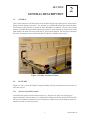
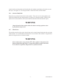
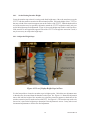
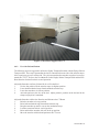
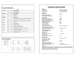
YR
ZEPH
Y
ZEPH R
Patient Transport Stretcher
Users Manual
DIACOR 2550 DECKER LAKE BLVD., SUITE 26, WEST VALLEY CITY, UTAH 84119
800 342-2679 / 801 467-0050 / FAX: 801 487-3258
www.diacorinc.com
[email protected]
800139 REV B
This manual contains the latest information at the time of publication. Diacor, Inc. reserves the right to revise this manual without
notice.
WARNING
The Zephyr Patient Transport Stretcher is intended for use
only by physicians qualified in diagnostic imaging or radiation oncology and experienced in gynecologic or prostate cancer planning or treatment, or by therapists at the
specific direction of such qualified physicians. It is the
sole responsibility of the physician to judge whether the
use of the Zephyr Patient Transport Stretcher is clinically
appropriate, whether the initial treatment plan is adequate
to achieve his or her clinical goals and whether the treatments are administered as prescribed.
Diacor, Inc. has appointed M. Devices Group as our EU Authorized
Representative. Contact Information: M. Devices Group, Marlborough House, Riding Street, Southport, PR8 1EW, United Kingdom,
Tel: +44 1704 544 944, Fax: +44 1704 544 050
Zephyr is a trademark of Diacor, Inc.
Diacor is a registered trademarks of Diacor, Inc.
Velcro is a registered trademark of Velcro Industries B.V.
SANI-CLOTH® is a registered trademark of Professional Disposables International
OneStep is a registered trademark of Hill-Rom Services, Inc.
Steering Plus is a trademark of Hill-Rom Services, Inc.
©2010 Diacor, Inc. Printed in U.S.A.
800139 REV B
Figure 1.1 Diacor Zephyr Patient Transport Stretcher
800139 REV B
800139 REV B
TABLE OF CONTENTS
INTRODUCTION
1
GENERAL DESCRIPTION
2.1
GENERAL
2.2
FEATURES
2.2.1 Stretcher Top and Extensions
2.2.2 Stretcher Top Extension Lock
2.2.3 Stretcher Top End Stops
2.2.4 Air Blower Transport Cage
2.2.5 Stretcher Top Height Stop
2.2.6 Stretcher Hand Rails
2.2.7 Wheel Locks
3
3
3
3
4
4
4
4
6
6
ACCESSORIES
3.1
GENERAL
7
7
UNPACKING, INSTALLATION, USE
4.1
GENERAL
4.2
UNPACKING AND INSPECTION
4.3
INSTALLATION
4.4
USE
4.4.1 Set the Resting Stretcher Height
4.4.1.1Adjust the Height Stops
4.4.2 Use with Sled and Patient
9
9
9
9
9
10
10
11
SERVICING
5.1
GENERAL
5.2
CLEANING
5.2.1 Cleaning Method
5.3
PERIODIC MAINTENANCE
5.4
HANDLING AND STORAGE
15
15
15
15
15
15
WARRANTY
6.1
GENERAL
6.2
WARRANTY DISCLAIMERS
6.3
WARRANTY PERFORMANCE
17
17
17
17
TECHNICAL INFORMATION
7.1
SPECIFICATIONS
19
19
i
800139 REV B
ii
800139 REV B
SECTION
INTRODUCTION
1
The Diacor Zephyr™ Patient Transport Stretcher with accessories provides the capability to easily
move a patient on the Zephyr Patient Transport Sled to or from a flat surface or flat table top (FTT).
The stretcher also provides the means to move a patient from one location to another.
The Patient Transport Stretcher consists of a flat metal top that is mounted to a conventional patient
stretcher. This flat metal surface has a hinged extension along each side that folds down to create a
bridge between the stretcher and a flat surface such as a CT FTT. The Patient Transport Stretcher
is part of a patient transport system that includes a Patient Transport Sled.
1
800139 REV B
2
800139 REV B
SECTION
GENERAL DESCRIPTION
2.1
2
GENERAL
This section contains a brief description of the features and physical characteristics of the Diacor
Zephyr Patient Transport Stretcher. The stretcher is a modified Hill-Rom Procedural Stretcher.
The features of this stretcher are described in the Hill-Rom User Manual. However, the top and
mattress of the Hill-Rom procedural stretcher are removed. Other features are retained such as the
push handles, the brake and steer pedals, the IV pole sockets and pole, the TuckAway OneStep®
side rails, the bumper system, the Steering Plus™ and the 8” urethane carpet casters.
Figure 2.1 Zephyr Stretcher Features
2.2
FEATURES
Figures 2.1 and 2.2 show the Zephyr Transport Stretcher and Top with pointers to the various features of the device.
2.2.1
Stretcher Top and Extensions
A flat metal top replaces the Hill-Rom stretcher top. Along the two long sides of the top are
hinged extensions of the top that serve as bridges between the stretcher top and the FTT (flat table
top) to or from which a patient on the sled is transferred. When not in use, the hinged extensions
should be locked in a vertical position.
3
800139 REV B
Figure 2.2 Zephyr Stretcher Height Stops and Top
2.2.2
Stretcher Top Extension Lock
Locks are provided at the head end of the stretcher to hold the top extensions in an upright position. The lock is a spring loaded block that prevents the extension from dropping to a horizontal
position. The user pulls the red handle of the lock away from the lock assembly and lifts the
extension to a vertical position. The handle is released and the block locks the extension in the
vertical position. Keeping the top extensions upright allows the stretcher side rails to be used
without interference from the top extensions. To lower the extension, the user pulls the red handle of the lock away from the lock assembly and lowers the extension to the horizontal position.
2.2.3
Stretcher Top End Stops
Two vertical pins at each end of the stretcher top stop the Zephyr Transport Sled from being
pushed off either end of the stretcher top.
2.2.4
Air Blower Transport Cage
A cage (not shown) is mounted at the head end of the stretcher and designed to hold the air blower used on the Zephyr Transport Sled. This allows the air blower to be carried with the stretcher
when it is moved from room to room.
2.2.5
Stretcher Top Height Stops
Two mechanical stops are provided to allow the stretcher to be held at a fixed position that matches the elevation of the CT FTT. The position of these stops is determined as part of the set up for
use with a CT FTT. They are hinged and after the stretcher top is lifted to its highest position are
rotated to a horizontal position to allow the stretcher to be lowered to its lowest elevation when a
patient first positions herself on the Zephyr Patient Transport Sled or leaves the sled and stretcher.
See Figure 2.3. After the patient is prepared to be moved to a new location or to be transferred
to the CT FTT, the stretcher top is lifted to its highest position and the two mechanical stops are
4
800139 REV B
Figure 2.3 Zephyr Stretcher Height Stops in Horizontal Position
Figure 2.4 Zephyr Stretcher Height Stops in Locked Vertical Position
5
800139 REV B
rotated to their vertical position and locked under the stretcher top and the top lowered to rest on
the stops. See Figure 2.4. The setup procedure is found in Section 4 of this manual.
2.2.6
Stretcher Hand Rails
Hand rails are provided on both sides of the stretcher. These rails can be released and moved
under the stretcher table top during transfer of a patient to or from the stretcher. Whenever the
patient is left on the stretcher or moved, the hand rails should be lifted and locked in place.
WARNING
Always lift and lock the stretcher hand rails whenever moving a patient or leaving the patient unsupervised.
2.2.7
Wheel Locks
The stretcher provides locks on the wheels that can be set and released from both sides and ends
of the stretcher. It is critical that the stretcher locks are set whenever the stretcher is stopped and a
patient is being moved to or from the stretcher.
WARNING
If the stretcher moves away from the FTT while a patient is being moved, the
patient could fall and suffer injury. It is imperative that the stretcher wheel locks
are set whenever a patient is being moved to or from the stretcher.
6
800139 REV B
SECTION
ACCESSORIES
3.1
3
GENERAL
The Zephyr Transport Sled includes two accessories. Push handles are included to be attached at
the head and foot ends of the stretcher. An IV pole is included that can be inserted in either end of
the stretcher top.
7
800139 REV B
8
800139 REV B
SECTION
UNPACKING, INSTALLATION, USE
4.1
4
GENERAL
The Diacor Zephyr Transport Stretcher is designed to be ready for use following removal from its
packing container and removal of packing protection restraints.
4.2
UNPACKING AND INSPECTION
When the Zephyr Transport Stretcher arrives, inspect all shipping containers for evidence of physical damage. If there are any dents, scratches or other evidence of physical damage to the boxes,
note the damage on the shipper’s copy of the bill of lading and file a claim against the shipper.
In the case of shortages or malfunctions, notify Diacor immediately to arrange for replacement or
repair. Refer to sections 6.3 for the discussion of replacement or repair of products under warranty.
Save all packing containers and materials for the Zephyr Transport Stretcher in case it needs to be
returned to Diacor for replacement or repair.
4.3
INSTALLATION
The Zephyr Transport Stretcher requires minimal inspection before it is ready to use. The two top
extensions should rotate freely on their hinges between the upright and horizontal positions and
lock in the upright position. The two stretcher top height stops should be locked in their upright
position. The two stretcher side rails should lift and lock in place. The stretcher brakes should
release and lock the wheels. The stretcher hydraulic lift system should allow the top to be raised
and lowered.
WARNING
The top of the stretcher is held in place by its weight. The user should not grasp
the top if they need to prevent the stretcher from tipping over.
4.4
USE
The stretcher is ready to be used upon removal from the shipping container. However, there are two
functions that must be accomplished.
First, adjustments to establish the fixed or resting height of the stretcher must be made to match a
determined height of the CT FTT. These adjustments must be made before the stretcher is used to
transfer a patient on a sled to another flat surface such as the CT FTT.
Second, the stretcher should be cleaned by the standard requirements of the user of any product that
may come in contact with a patient.
9
800139 REV B
4.4.1
Set the Resting Stretcher Height
Lower the stretcher top so that it is resting on the fixed height stops. Move the stretcher next to the
CT FTT with the stretcher extension in the horizontal position. Adjust the height of the CT FTT so
that one or both of the extension supports rest on the surface of the CT FTT. Both the head and foot
end of the stretcher may be separately adjusted to match the CT FTT height but usually only one
end of the height stops need adjustment. Figure 4.1 shows the height stops in their vertical position.
If the stretcher is used against the opposite side of the CT FTT or the opposite extension is used, it
may be necessary to readjust the height stops.
4.4.1.1 Adjust the Height Stops
Figure 4.1 View of Zephyr Height Stops in Place
Use the foot pedals to elevate the stretcher top to its highest point. Unlock the two adjustment nuts
so that they may be rotated about the threaded vertical post. See Figure 4.1. Rotate the adjustment
nuts to fine tune the height of the stretcher top so that the extension supports at both ends of the
stretcher extension just rest on the surface of the FTT. See Figure 4.2. The stretcher top needs to be
lowered so it rests on the height stop to determine if the adjustment is correct. It may take several
incremental adjustments to achieve the final adjustment.
10
800139 REV B
Figure 4.2 Extension Support on FTT
4.4.2
Use with Sled and Patient
The following steps are suggested to utilize the Zephyr Transport Stretcher with the Zephyr Patient
Transport Sled. These steps assume that the sled is centered and on one side of the stretcher top to
allow a patient to get on or off the sled. They also assume that the stretcher stops have been set to
match the CT FTT. Refer to the User Manuals for the Zephyr Patient Transport Sled and the HillRom Stretcher for detail on their use and operation.
Adjust the Stretcher to Allow a Patient Sit On or Exit the Sled
1.
Use the foot pedal to lift the stretcher top to its highest position.
2.
Lower both mechanical stops from beneath the stretcher top.
3.
Lower the stretcher to its lowest position.
4.
Assist the patient as she sits on the sled. Adjust patient’s position on the sled and in the
stirrups to physician’s standards.
Adjust the Stretcher to Move the Stretcher and Patient to the CT Room
1.
Raise the stretcher to its top position.
2.
Raise both mechanical stops beneath the stretcher top.
3.
Drop the stretcher top until it rests on the mechanical stops.
4.
Lock the extensions in their vertical position.
5.
Raise and lock the stretcher side rails in the up position.
6.
Move the stretcher with sled and patient to the CT room.
11
800139 REV B
Adjust the Stretcher to Allow Sled and Patient Transfer to CT FTT
1.
Drop the side rail and unlock the stretcher extension next to the CT table.
2.
Set the elevation of the CT FTT to the value determine during the set up procedure.
3.
Move the stretcher close to the CT FTT so that the stretcher extension supports rest on the
CT FTT.
4.
Lock the wheels of the stretcher.
Transfer the Sled and Patient to the CT FTT
1.
Connect the air blower to the sled and to electrical power.
2.
Turn the blower on and with two therapists, slide the sled on the stretcher to the CT FTT
until the sled is fully supported by the CT FTT. Then turn the air blower off.
Transfer the Sled and Patient on the CT FTT
1.
Place the four sled guide pins in a vertical position.
2.
Turn on the Air Blower to move the sled and patient to other positions on the CT FTT.
Use two people to move the sled. Turn off the Air Blower when the desired position is
reached.
Reverse these steps as the sled and patient are moved from the CT FTT to the stretcher and the
patient is assisted from the sled.
WARNING
Lock the stretcher wheels before turning the air blower on and before moving
the sled and patient to or from the stretcher.
WARNING
Make sure both patients and users keep their fingers above the sled so prevent
pinching when the air blower is turned off and the sled settles to its supporting
surface.
WARNING
It is extremely easily to move a patient that has been lifted by the air pillow.
However, two people should assist in moving the patient when ever the sled is
supported by the air pillow. Alignment guide pins help insure that the sled remains on the CT FTT but when only one person moves the patient, that person
may cause movements of the sled that defeat the purpose of the guide pins.
12
800139 REV B
WARNING
Before sliding the sled from the CT FTT to the stretcher, the four alignment pins
must be adjusted so that the pins are horizontal. Failure to do so may cause
damage to the CT FTT and may make movement of the sled difficult.
13
800139 REV B
14
800139 REV B
5
SECTION
SERVICING
5.1
GENERAL
The Diacor Zephyr Patient Transport Stretcher requires careful handling and cleaning following
each use but generally requires minimal service.
5.2
CLEANING
The Zephyr Patient Transport Stretcher and accessories experience noncritical patient contact. It is
important to thoroughly clean these parts following each use.
5.2.1
Cleaning Method
After each use, wipe the surfaces of the stretcher and the support accessories with wipes containing
a mild cleaning and disinfecting solution of 14% alcohol and active quaternary ammonium chlorides or a similar disinfecting solution. (One such solution is offered by Professional Disposables
International with a trade name of SANI-CLOTH® PLUS). After the cleaning process is complete, let the cleaned surfaces air dry. Do not use water as either a cleaning or rinsing agent. Never
use aerosol cleaning sprays, cleaning agents, solvents or abrasive detergents.
5.3
PERIODIC MAINTENANCE
Periodic checks of the Zephyr Patient Transport Stretcher should be done to insure the parts are not
worn and require repair or replacement.
5.4
HANDLING AND STORAGE
Handle the stretcher carefully to prevent damage. Store in a safe place when not used.
15
800139 REV B
16
800139 REV B
SECTION
WARRANTY
6.1
6
GENERAL
The Zephyr Patient Transport Stretcher and all the associated parts for this system are warranted by
Diacor for a period of one (1) year from the date of shipment.
The Diacor warranty coverage is limited to defective materials or workmanship. The warranty is
void if the Zephyr Patient Transport Stretcher has been damaged by accident, unreasonable or improper use, neglect, or other causes not arising out of defects in material or workmanship.
6.2
WARRANTY DISCLAIMERS
The express warranty provided herein is in lieu of any and all implied warranties arising out of the
sale of the Zephyr Patient Transport Stretcher, including but not limited to the implied warranties of
merchantability and fitness for a particular purpose. Diacor shall not be liable for loss of use of the
Zephyr Patient Transport Stretcher or other incidental or consequential costs, expenses, or damages
incurred by the customer or other user.
6.3
WARRANTY PERFORMANCE
During the stated warranty period, the Zephyr Patient Transport Stretcher will be repaired or replaced, at the option of Diacor, Inc., with a new or reconditioned Zephyr Patient Transport Stretcher when the units are returned shipping prepaid to Diacor, Inc., 2550 Decker Lake Blvd., Suite
26, West Valley City, Utah 84119. Please contact Diacor, 800-342-2679 or 801-467-0050, for a
Return Material Authorization (RMA) prior to sending the defective unit to us. The replacement of
a Zephyr Patient Transport Stretcher will not extend the expressed warranty stated herein beyond
the original warranty period.
17
800139 REV B
18
800139 REV B
SECTION
TECHNICAL INFORMATION
7.1
7
SPECIFICATIONS
Weight
320 lb.
145.5 kg.
83 in.
210.8 cm.
43.8in.
111.2 cm.
Length
Width
(with side rails down and extensions
down)
Width
(with side rails up)
Side Rail Length
36 in.
91.4 cm.
47 in.
119.4 cm.
24 in. x 50.5 in.
61 cm. x 128.3 cm.
8 in.
20.3 cm.
600 lb.
272 kg.
Wheel Base
Caster Size
Maximum Working Load
19
800139 REV B