1
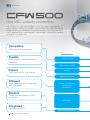
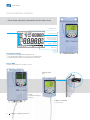
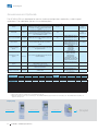
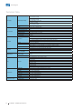
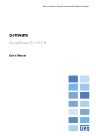
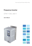
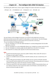
Motors | Automation | Energy | Transmission & Distribution | Coatings CFW500 Machinery Drives Variable Speed Drives www.weg.net One VSD, endless possibilities The CFW500 has advanced technology Plug & Play options, developed for fast commissioning, providing great flexibility and competitive advantage while offering excellent performance and reliability. Designed for exclusively industrial or professional use, is perfect for OEM, system integrators, panel installers and End Users providing great benefit and added value. Compatible Wide range of accessories Characteristics Flexible Wide range of accessories and functions Plug-in module Flash memory module Robust SoftPLC 150% overload for one minute High overload capacity Efficient High performance for machines and processes Functions to streamline operation and performance Reliable Same trustworthiness of WEG products WEG quality Integrated Fieldbus networks Communication networks 2 CFW500 - Variable Speed Drives www.weg.net Advantages Benefits The optional communication network and I/O modules are fast and easily installed, allowing adaptation of the standard VSD to each application. Time saving, standardization and optimized costs according to the necessity. Within seconds, it is possible to download the SoftPLC program and parameter set from a CFW500 to others without powering them up. Fast, easy and reliable programming for manufacturers that produce machines in large scale. Built-in PLC (SoftPLC), allowing the VSD, motor and application to work in an interactive way. It allows the user to implement customised logic and applications. It eliminates the necessity of an external PLC, reducing costs, optimizing space and simplifying the system. It withstands an overload of 150% for one minute every 6 minutes, at an ambient temperature of 50 °C. It does not require oversizing the VSD. PID: process control. Sleep: disables the VSD automatically. Energy saving. Flying start: allows control of a motor that is turning freely, accelerating it from the speed at which it was running. It allows fast operating response of the machine and prevents occasional mechanical breakdowns. Ride through: keeps the VSD in operation during voltage dips. It prevents machine stoppage and downtime. 100% of the VSDs are tested with load at the factory under rated conditions. High reliability. Protection against ground fault, short circuit, overtemperature and others. It prevents damage to the inverter which can be caused by adverse situations, normally external factors. Thermal protection of IGBTs based on manufacturer curve. Conformal Coating (Tropicalization) as Standard. Classified as 3C2 according to IEC 60721-3-3. VSD lifetime is extended: protection against chemically active substances, related to contamination from the atmosphere. CANopen, DeviceNet, Profibus-DP, Ethernet-IP, Profinet-IO, Modbus-TCP and Modbus-RTU. Full integration with process network. CFW500 - Variable Speed Drives 3 www.weg.net Easy Configuration Fast commissioning Innovative design, compact and uniform Optimised cost x benefit Plug-in Modules Connections and interfaces for flexibility. Conformal Coating (Tropicalization) as Standard Fan Simple and fast removal. With plug-in module CFW500-IOS 4 5 1 4 Increasing the lifetime, protecting the electronic boards against corrosive atmospheres. Classified as 3C2 according to IEC 60721-3-3. 2 3 CFW500 - Variable Speed Drives 1 - Power terminals 2 - Access to DC link 3 - Motor terminals 4 - Control terminals (I/Os) 5 - RS485 port www.weg.net Applications Centrifugal pumps Process dosing pumps Fans / exhausters Mixers Compressors Conveyor belts Roller tables Granulators / palletizers Dryers Rotary filters CFW500 - Variable Speed Drives 5 www.weg.net Human-Machine Interface View three selected parameters at the same time CFW500 status Secondary display Parameter groups Unit of measurement (it refers to the value of the main display) Bar for variable monitoring Main display Soft keys Friendly Programming Oriented start-up: programming step by step Easy and intuitive operation, fast access to the parameters Parameter group: it directs to the parameters of interest Remote HMI Solution for panel door or machine console. CFW500-HMIR IP54 RS485 Included in Include n all plug-in modules module CFW CFW500-CCHMIRXM X = up to 10 m 6 CFW500 - Variable Speed Drives www.weg.net Energy Efficiency In industry, electric motors are responsible for nearly 70% of all the electric energy consumed. Using a VSD, it is possible to reduce consumption by up to 40%. Besides being efficient in the control of electric motors, they also reduce machine wear, save raw materials, improve process quality and increase productivity. Visit the WEG website to calculate how much energy can be saved by using the CFW500 VSD. Ensures energy efficiency for your equipment and machines. Save money and contribute to the conservation of the environment. Certifications CFW500 - Variable Speed Drives 7 www.weg.net SuperDrive G2 Software application to program, control and monitor WEG VSDs. To connect to a computer a plug-in is needed. USB plug-in module Friendly environment FREE download at www.weg.net Trend Function Online graphic monitoring of parameters/variables Possibility to export an image with the respective graph based upon the selected period Changing and Monitoring Parameters in a List/Table Parameter settings can be stored in a computer file format. Status Monitoring Operation with HMI Online parameter editing. 8 Upload/download parameters from the PC to the CFW500 and vice versa Offline editing of the parameters stored on the PC CFW500 - Variable Speed Drives www.weg.net SoftPLC - Built-in the Standard Product Functionalities of a PLC available as standard, allowing the creation of applications. The WLP software and the SoftPLC functionality are a smart and simple way to make your CFW500, motor and application work together. To connect to a computer a plug-in is needed. Easy programming: Ladder Speed reference Trend Function Online graphic monitoring of parameters/ variables Configurable up to six channels Contacts and coils Comparators and math functions Counters and timers FREE download at www.weg.net PID User block protected by password Online Monitoring Parameters/Variables List Enable/Disable I/Os It simplifies and speeds up the validation of the application. Parameter Edition For changing the parameters values. I/Os Monitoring CFW500 - Variable Speed Drives 9 www.weg.net Coding The CFW500 code identifies its construction characteristics, nominal current, voltage range and optionals. Using the smart code, it is possible to select the CFW500 required for your application simple and quickly. Product and series CFW500 Model identification Frame size Rated current N° of phases Rated voltage A 02P6 T 4 Braking¹) Degree of protection¹) Conducted emission level¹) Hardware version Software version NB 20 C2 H00 --- Check table below NB = without dynamic braking DB = with dynamic braking 20 = IP20 N1 = NEMA1 enclosure CFW500 Blank = with no RFI filter C2 = according to category 2 of IEC 61800-3 standard, with internal RFI flter C3 = according to category 3 of IEC 61800-3 standard, with internal RFI flter H00 = without plug-in module Blank = standard Sx = special software Frame sizes A B A B A B C D A B C D Output current 01P6 = 1.6 A 02P6 = 2.6 A 04P3 = 4.3 A 07P0 = 7.0 A 07P3 = 7.3 A 10P0 = 10 A 01P6 = 1.6 A 02P6 = 2.6 A 04P3 = 4.3 A 07P3 = 7.3 A 10P0 = 10 A 07P0 = 7.0 A Input Power supply voltage Degree of protection Blank or C3 DB B = single-phase or three-phase power supply Conducted emission level3) Blank or C2 NB S = single phase power supply C2 NB 2 = 200... 240 V DB Blank NB 09P6 = 9.6 A 16P0 = 16 A 24P0 = 24 A 28P0 = 28 A 33P0 = 33 A 47P0 = 47 A 01P0 = 1.0 A 01P6 = 1.6 A 02P6 = 2.6 A 04P3 = 4.3 A 06P1 = 6.1 A 02P7 = 2.7 A 04P3 = 4.3 A 06P5 = 6.5 A 10P0 = 10 A 14P0 = 14 A 16P0 = 16 A 24P0 = 24 A 31P0 = 31 A Braking IGBT2) DB DB T = three-phase power supply 20 or N1 DB NB Blank or C3 Blank or C2 Blank or C3 T = three-phase power supply 4 = 380...480 V DB Blank or C2 Blank or C3 DB Blank or C3 DB Blank or C3 Notes: 1) To know which models have these options in the standard product the table above should be checked. 2) RFI filter. Categories: - Category C1: inverters with voltages below 1,000 V, for use in the First Environment. - Category C2: inverters with voltages below 1,000 V, with plugs or mobile installation, when used in the “First Environment”, must be installed and started-up by a qualified professional. - Category C3: inverters with voltages below 1,000 V, developed for use in the Second Environment and not designed for use in the “First Environment”. Environments: - First Environment: environments that include household installations, such as buildings directly connected, without intermediate transformer, to a lowvoltage power supply grid, which supplies buildings used for domestic purposes. - Second Environment: includes all the buildings other than those directly connected to a low-voltage power supply grid, which supplies buildings used for domestic purposes. To install external RFI filters, refer to the CFW500 user manual. 10 CFW500 - Variable Speed Drives www.weg.net Drive Ratings The correct way to select a VSD is matching its output current with the motor rated current. The tables below present the expected motor power for each VSD model. Use the motor power ratings below only as a guideline. Motor rated currents may vary with speed and manufacturer. IEC motor powers are based on WEG 4-pole motors; NEMA motor powers are based on NEC table 430-150. Motor Voltages Between 220 V and 230 V Motor Voltages Between 380 V and 480 V 3Ø Model CFW500 A 01P6 S2 CFW500 A 02P6 S2 CFW500 A 04P3 S2 CFW500 A 07P0 S2 CFW500 A 01P6 B2 CFW500 A 02P6 B2 CFW500 A 04P3 B2 CFW500 B 07P3 B2 CFW500 B 10P0 B2 CFW500 A 07P0 T2 CFW500 A 09P6 T2 CFW500 B 16P0 T2 CFW500 C 24P0 T2 CFW500 D 28P0 T2 CFW500 D 33P0 T2 CFW500 D 47P0 T2 A 1.6 2.6 4.3 7 1.6 2.6 4.3 7.3 10 7 9.6 16 24 28 33 47 60 Hz 220 V 60 Hz 230 V kW 0.25 0.55 1.1 1.5 0.25 0.55 1.1 1.5 2.2 1.5 2.2 4 5.5 7.5 9.2 11 HP 0.25 0.5 1 2 0.25 0.5 1 2 3 2 3 5 7.5 10 12.5 15 HP 0.33 0.5 1 2 0.33 0.5 1 2 3 2 3 5 7.5 10 10 15 Power supply Model CFW500 A 01P0 T4 CFW500 A 01P6 T4 CFW500 A 02P6 T4 CFW500 A 04P3 T4 CFW500 A 06P1 T4 CFW500 B 02P6 T4 CFW500 B 04P3 T4 CFW500 B 06P5 T4 CFW500 B 10P0 T4 CFW500 C 14P0 T4 CFW500 C 16P0 T4 CFW500 D 24P0 T4 CFW500 D 31P0 T4 3Ø 200-240 V 1/3Ø 1Ø Power supply IEC NEMA 50 Hz 230 V 380-480 V IEC Rated current Rated current 400V A 1 1.6 2.6 4.3 6.1 2.6 4.3 6.5 10 14 16 24 31 0.25 0.55 1.1 1.5 3 1.1 1.5 3 4 5.5 7.5 11 15 NEMA 50 Hz 415 V 60 Hz 460 V 60 Hz 460 V kW 0.25 0.75 1.1 1.5 3 1.1 1.5 3 4 7.5 7.5 11 15 HP 0.5 1 1.5 3 4 1.5 3 4 7.5 10 12.5 15 25 HP 0.33 0.75 1 2 3 1 2 3 7.5 10 10 15 25 Dimensions and Weights H IP20 Frame size H mm W mm D mm Weight Kg A 189.1 75.2 149.5 0.8 B 199.1 100.2 160.1 1.2 C 210 135.2 165.1 2 D 306.6 180 166.5 4.3 H mm W mm D mm Weight Kg D W NEMA1 Frame size A 223 75.2 149.5 1.05 B 243.3 100.2 160.1 1.49 C 254.8 135.2 165.1 2.35 D 362 180 166.5 4.8 H D W CFW500 - Variable Speed Drives 11 www.weg.net Accessories and Optionals The CFW500 VSD was developed to meet the hardware configurations required by a wide range of applications. The table below presents the available options: Option Type1) Description Optional item code2) Used to reduce the disturbance conducted from the CFW500 to the power supply, in the high frequency band C2 or C3 (>150 kHz), according to standards 61800-3 and EN 55011. Used in high-inertia applications for the fast stop of the motor by means of an external braking resistance. DB Resistance not included. To specify the braking resistance, refer to the CFW500 user manual. RFI filter Optional Braking IGBT Optional Degree of protection NEMA1 Optional or accessory Used for the CFW500 VSD to have degree of protection NEMA1 and/or when metallic conduits are used for the cables. N1 Cable shield kit Accessory Used to shield the power and control cables. Important: for the version with RFI filter, this filter comes with the product. - I/O expansion modules (plug-in)3) Accessory Used to configure the I/O points according to the needs of the application/machine. Communication module (plug-in) Accessory Used to communicate CFW500 with the main networks of the market (Fieldbus). Flash memory module (plug-in) Accessory Remote HMI Accessory Cables for remote HMI Specifi Accessory Plug-in Modules cation3) Inputs Plug-in module CFW500-IOS CFW500-IOD CFW500-IOAD CFW500-IOR CFW500-CUSB CFW500-CRS485 CFW500-CRS232 CFW500-CCAN CFW500-CPDP CFW500-CEMB-TCP CFW500-CEPN-IO CFW500-CETH-IP - Used to interconnect the CFW500 to the remote HMI (CFW500-HMIR). Available - Factory installation only - Factory installation only CFW500-KN1A (frame size A) CFW500-KN1B (frame size B) CFW500-KN1C (frame size C) CFW500-KN1D (frame size D) CFW500-KPCSA (frame size A) CFW500-KPCSB (frame size B) CFW500-KPCSC (frame size C) CFW500-KPCSD (frame size D) CFW500-IOS CFW500-IOD CFW500-IOAD CFW500-IOR CFW500-CUSB (USB) CFW500-CCAN (CANopen /DeviceNet) CFW500-CRS232 CFW500-CRS485 CFW500-CPDP (Profibus-DP) CFW500-CEMB-TCP (Modbus-TCP) CFW500-CEPN-IO (Profinet-IO) CFW500-CETH-IP (Ethernet-IP) - Used to download the program from a CFW500 to others without having to power them up. Used to transfer the operation to the panel door or machine console. Maximum distance of 10 m. Degree of protection IP54. Accessory model Factory or user installation User installation - - - CFW500-MMF - - CFW500-HMIR - - CFW500-CCHMIRXM, where cables with lengths (X) of 1, 2, 3, 5, 7,5 and 10 meters - Outputs Digital Analog Analog Digital relay Digital transistor USB Port 4 8 6 5 4 4 2 2 2 2 2 2 1 1 3 1 1 2 1 1 1 1 1 1 1 1 2 1 1 1 1 1 1 1 1 1 1 1 1 4 1 2 1 1 1 1 1 1 1 4 3 1 1 1 1 1 1 1 1 1 1 - Fieldbus communication Modbus-RTU Others RS485 1 1 1 1 1 2 1 1 1 1 1 1 RS232 CANopen / DeviceNet Profibus-DP Modbus-TCP Profinet-IO Ethernet-IP Power supply 10 V 24 V 1 1 1 1 1 1 1 - 1 1 1 1 1 1 1 1 1 1 1 1 Notes: 1) Optional = hardware resources added to the CFW500 in the manufacturing process accessory = hardware resource requested as a separated item. 2) Request the product according to the code available on page 10. 3) All plug-in modules have at least one RS485 port. The CFW500-CRS485 plug-in module has two RS485 ports. The CFW500 allows installing one plug-in module per unit. Step by Step 1 - Remove cover 12 2 - Insert accessory CFW500 - Variable Speed Drives 3 - Close cover Simple! www.weg.net Block Diagram 3 1 = DC link connection 2 = Braking resistor connection2) 3 = External DC inductor connection3) DC+ 1 2 1 BR DC- Pre-load Power supply Rectifier PE Motor IGBT Internal RFI filter DC link Feedbacks: -voltage -current POWER PE CONTROL Power supplies for electronics and for interface between power and control Keypad CPU 32 bits ‘‘RISC’’ EEPROM (memory) Remote keypad (CFW500-HMIR) CONTROL CFW500-IOS PLUG-IN MODULE1) RS485 Software WLP SuperDrive G2 Modbus Interfaces (RS232, RS485 or USB) Power supply 10 V Power supply 24 V Analog output (AO1)1) Plug-In module Digital output DO1 (RL1)1) Digital inputs1) (DI1 to DI4) Digital output DO2 (TR)1) Analog inputs1) (AI1) Accessory Flash memory (CFW500-MMF) Notes: 1) The number of inputs and outputs (analog and digital), as well as other resources, may vary according to the used plug-in module. For further information, refer to the CFW500 user manual. 2) Not available for frame size A. Braking resistance not included. 3) Available for frame size D only. DC link inductor not included. CFW500 - Variable Speed Drives 13 www.weg.net Technical Data 1-phase, 200-240 V ac (+10%-15%) 0.25 to 2 HP (0.25 to 1.5 kW) Power supply Voltage and power range 1-phase/3-phase, 200-240 V ac (+10%-15%) 0.25 to 3 HP (0.25 to 2.2 kW) 3-phase, 200-240 V ac (+10%-15%) 2 to 15 HP (1.5 to 5.5 kW) 3-phase, 380-480 V ac (+10%-15%) 0.5 to 25 HP (0.25 to 15 kW) Motor connection Supply frequency 50/60 Hz (48 Hz to 62 Hz) Voltage 3-phase, 0-100% of supplied voltage Output frequency 0 a 500 Hz Displacement power factor >0.97 Overload capacity 1.5 x In (drive) for 1 minute every 6 minutes Switching frequency Default 5 kHz (selectable 2.5 to 15 kHz) Aceleration time 0.1 to 999s Deceleration time 0.1 to 999s 40 ºC - NEMA1 Temperature 40 ºC - IP20 side by side and/or with RFI filter 50 ºC - IP20 without RFI filter (except the models for 9.6 A and 24 A for 200-240 V) 2% of current derating for each ºC above the specific operating temperature, limited to an increase of 10 ºC Environment Humidity Altitude Degree of protection V/f control Performance Vector control (VVW) Braking methods 5% to 95% non-condensing Up to 1,000 m - rated conditions 1,000 m to 4,000 m - 1% of current derating for each 100 m above 1,000 m of altitude IP20 or NEMA1 (with kit NEMA1) Speed regulation: 1% of the rated speed (with slip compensation) Speed variation range: 1:20 Speed regulation: 1% of the rated speed Speed variation range: 1:30 Dynamic braking Braking IGBT available as standard for frame sizes B, C and D. An external resistor must be installed for dynamic braking capability DC braking DC current applied to the motor Overcurrent/phase-phase short circuit in the output Overcurrent/phase-ground short circuit in the output Under/overvoltage Safety Protection Overtemperature in the heatsink Overload in the motor Overload in the power module (IGBTs) External alarm / fault Setting error Communication Chokes (external as accessory) 14 Modbus-RTU All plug-in modules for RS485 and CFW500-CRS232 for RS232 Profibus-DP Plug-in module CFW500-CPDP DeviceNet Plug-in module CFW500-CCAN CANopen Plug-in module CFW500-CCAN Modbus-TCP Plug-in module CFW500-CEMB-TCP Profinet-IO Plug-in module CFW500-CEPN-IO Ethernet-IP Plug-in module CFW500-CETH-IP AC input chokes To reduce THD AC output chokes For longer motor cables CFW500 - Variable Speed Drives www.weg.net Technical Data - Standards Safety standards Electromagnetic Compatibility (EMC) Standards Mechanical construction standards UL 508C Power conversion equipment. UL 840 Insulation coordination including clearances and creepage distances for electrical equipment. EN 61800-5-1 Safety requirements electrical, thermal and energy. EN 50178 Electronic equipment for use in power installations. EN 60204-1 Safety of machinery. Electrical equipment of machines. Part 1: General requirements. Note: For the machine to comply with this standard, the manufacturer of the machine is responsible for installing an emergency stop device and equipment to disconnect the input power supply. EN 60146 (IEC 146) Semiconductor converters. EN 61800-2 Adjustable speed electrical power drive systems - Part 2: General requirements - Rating specifcations for low voltage adjustable frequency AC power drive systems. EN 61800-3 Adjustable speed electrical power drive systems - Part 3: EMC product standard including specifc test methods. EN 55011 Limits and methods of measurement of radio disturbance characteristics of industrial, scientifc and medical (ISM) radio-frequency equipment. CISPR 11 Industrial, scientifc and medical (ISM) radio-frequency equipment - Electromagnetic disturbance characteristics Limits and methods of measurement. EN 61000-4-2 Electromagnetic compatibility (EMC) - Part 4: Testing and measurement techniques - Section 2: Electrostatic discharge immunity test. EN 61000-4-3 Electromagnetic compatibility (EMC) - Part 4: Testing and measurement techniques - Section 3: Radiated, radio-frequency, electromagnetic feld immunity test. EN 61000-4-4 Electromagnetic compatibility (EMC) - Part 4: Testing and measurement techniques - Section 4: Electrical fast transient/ burst immunity test. EN 61000-4-5 Electromagnetic compatibility (EMC) - Part 4: Testing and measurement techniques - Section 5: Surge immunity test. EN 61000-4-6 Electromagnetic compatibility (EMC) - Part 4: Testing and measurement techniques - Section 6: Immunity to conducted disturbances, induced by radio-frequency fields. EN 60529 Degrees of protection provided by enclosures (IP code). UL 50 Enclosures for electrical equipment. CFW500 - Variable Speed Drives 15 www.zest.co.za Johannesburg Rustenburg Zest Electric Ghana Limited 47 Galaxy Avenue, Linbro Business Park Private Bag X10011, Sandton 2146 GPS: S 26º 4’ 10.92” E 28º 6’ 45.88” Tel: +27 (0) 11 723 6000 Fax: +27 (0) 11 723 6001 [email protected] 6 Kgwebo Road, Mabe Business Park Old Pretoria Road P O Box 649, Rustenburg 0300 GPS: S 25º 41’ 14.1” E 27º 15’ 38.78” Tel: +27 (0) 14 594 0450 Fax: +27 (0) 14 594 0471 [email protected] 15, Third Close Street, Airport Residential Area, Accra, Ghana GPS: N 5º 36’ 54.90” W 0º 10’ 50.02” Tel: +233 30 27 664 90 Fax: +233 30 27 664 93 Cell: +233 540 898 466 [email protected] Generator Set Division Johannesburg Port Elizabeth EnI Electrical Electrical/Instrumentation Engineering and Contracting 47 Galaxy Avenue, Linbro Business Park GPS: S 26º 4’ 10.92” E 28º 6’ 45.88” Tel: +27 (0) 11 723 6000 Fax: +27 (0) 11 723 6001 [email protected] 55 Burman Road, Deal Party P O Box 2565, North End 6056 GPS: S 33º 54’ 15.7” E 25º 36’ 50.3” Tel: +27 (0) 41 486 1262 Fax: + 27 (0) 41 486 1658 [email protected] Cape Town Richards Bay 9 Omuramba Road, Marconi Beam Montague Gardens, Milnerton P O Box 36582, Chempet 7442 GPS: S 33º 52’ 42.1” E 18º 30’ 39.1” Tel: +27 (0) 21 551 2710 Fax: +27 (0) 21 551 2776 [email protected] 5 Brass Link, Unit 1A, Alton P O Box 30206, Richards Bay 3900 GPS: S 28º 45’ 3.02” E 32º 1’ 47.82” Tel: +27 (0) 35 751 1607 Fax: +27 (0) 35 751 1426 [email protected] 13 Benbow Avenue, Epping Industrial 1 P O Box 231, Eppingdust, 7475 GPS: S 33º 55’ 48.65” E 18º 32’ 12.6” Tel: +27 (0) 21 507 7200 Fax: +27 (0) 21 507 7201 [email protected] Durban 51 Island Circle, Riverhorse Business Estate P O Box 20667 Durban North 4016 GPS : S 29º 46’ 5.53” E 31º 0’ 21.04” Tel: +27 (0) 31 569 7260 Fax: +27 (0) 31 569 6755 [email protected] 3 Schabort Street, Trichardt P O Box 1626, Secunda 2302 GPS: S26º 29’ 28.08” E29º 13’ 15.64” Tel: +27 (0) 17 638 1571 Fax: +27 (0) 17 638 1572 [email protected] Middelburg 6 Wicht Street, Vaalbank, Middelburg GPS: S 25º 47’ 7.70” E 29º 28’ 42.33” Tel: +27 (0) 13 246 2849 Fax: +27 (0) 13 246 2850 [email protected] Shaw Controls Motor Control Centres, Packaged Switchgear Solutions 18 Mt. Ida Road, Robertsham P O Box 39195, Booysens 2016 GPS: S 26º 14’ 43.8” E 28º 00’ 59.3” Tel: +27 (0) 11 680 4534 Fax: +27 (0) 11 433 3569 [email protected] Zest Energy Integrated Power Generation, Co–Generation and Energy Solutions 21 Galaxy Avenue, Linbro Business Park Private Bag X10011, Sandton 2146 GPS: S 26º 4’ 23.4” E 28º 6’ 49.5” Tel: +27 (0) 11 723 6000 Fax: +27 (0) 11 723 6001 [email protected] WEG Transformers Africa Locally Manufactured Transformers and MiniSubstations 38 Van Deventer Street, Wadeville Germiston GPS: S 26º 15.941’ E 28º 12.46’ Tel: +27 (0) 11 827 3458 Fax: +27 (0) 11 827 1668 [email protected] Cod: 50041190 | South Africa | Rev: 00 | Date (m/y): 06/2015 The values shown are subject to change without prior notice. Trichardt Generator Set & Panel Division Cape Town 47 Galaxy Avenue, Linbro Business Park Private Bag X10011, Sandton 2146 GPS: S 26º 4’ 10.92” E 28º 6’ 45.88” Tel: +27 (0) 11 792 2803 Fax: +27 (0) 11 723 6001 [email protected]