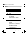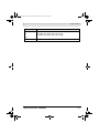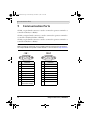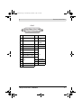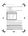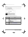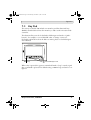
1
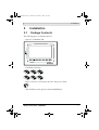
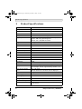
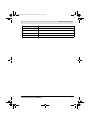
H-T70
Installation and Operation Manual
MAEN922 2007-11
English
MAEN922.book Page 1 Wednesday, November 7, 2007 9:57 AM
Foreword
H-T70 Installation and Operation Manual
Foreword
H-T70 is a Human Machine Interface (HMIs) with a 7” TFT Liquid Crystal
Display, and is water- and dust-resistant according to IP65/NEMA 4X (indoor
use only).
H-T70 is CE-marked and meets your need to be highly transient-resistant
while in operation.
Also, its compact design makes connections with other machinery more flexible, thus achieving the optimal performance of your machines.
H-Designer is used to design applications of H-T70; it is reliable, user-friendly
and compatible with many models.
© Beijer Electronics AB, MAEN922, 2007-11
Please read the entire installation manual prior to installing and using this equipment. Only qualified personnel may install, operate or repair this equipment. Beijer Electronics AB is not responsible for modified,
altered or renovated equipment. Because the equipment has a wide range of applications, users must
acquire the appropriate knowledge to use the equipment properly in their specific applications. Persons
responsible for the application and the equipment must themselves ensure that each application is in
compliance with all relevant requirements, standards and legislation in respect to configuration and safety.
Only parts and accessories manufactured according to specifications set by Beijer Electronics AB may be
used.
BEIJER ELECTRONICS AB SHALL NOT BE LIABLE TO ANYONE FOR ANY DIRECT,
INDIRECT, SPECIAL, INCIDENTAL OR CONSEQUENTIAL DAMAGES RESULTING FROM
THE INSTALLATION, USE OR REPAIR OF THIS EQUIPMENT, WHETHER ARISING IN
TORT, CONTRACT, OR OTHERWISE. BUYER'S SOLE REMEDY SHALL BE THE REPAIR,
REPLACEMENT, OR REFUND OF PURCHASE PRICE, AND THE CHOICE OF THE APPLICABLE REMEDY SHALL BE AT THE SOLE DISCRETION OF BEIJER ELECTRONICS AB.
Beijer Electronics, MAEN922
MAEN922.book Page 3 Wednesday, November 7, 2007 9:57 AM
Contents
Contents
1 Safety Precautions................................................................................... 5
2 Installation.............................................................................................. 7
2.1
Package Contents......................................................................... 7
3 Product Specifications............................................................................. 8
3.1
Description of Parts ................................................................... 10
3.2
External and Cut-out Dimensions.............................................. 11
3.3
Mounting Procedure .................................................................. 11
3.4
Grounding ................................................................................. 12
3.5
Power Supply and Wiring .......................................................... 13
4 Dip Switches......................................................................................... 14
5 Communication Ports........................................................................... 16
6 Touch Screen Calibration...................................................................... 18
7 Operation ............................................................................................. 19
7.1
Self Test ..................................................................................... 19
7.2
System Menu ............................................................................. 20
7.3
Key Pad...................................................................................... 21
7.4
Bench and Function Tests .......................................................... 22
7.5
Setting Parameters...................................................................... 22
7.6
Downloading an Application ..................................................... 23
7.7
Uploading an Application .......................................................... 24
7.8
Uploading/Downloading a Recipe ............................................. 25
7.9
Copying an Application ............................................................. 26
7.10
Passwords................................................................................... 27
Beijer Electronics, MAEN922
MAEN922.book Page 4 Wednesday, November 7, 2007 9:57 AM
Contents
Beijer Electronics, MAEN922
MAEN922.book Page 5 Wednesday, November 7, 2007 9:57 AM
Safety Precautions
1
Safety Precautions
Both the installer and the owner and/or operator of the operator terminal must
read and understand this installation manual.
General
– Only qualified personnel may install or operate the operator terminal.
– The operator terminal must be installed according to the installation instructions.
– The operator terminal is designed for stationary installation on a plane surface,
where the following conditions are fulfilled:
• no high explosive risks
• no strong magnetic fields
• no direct sunlight
• no large, sudden temperature changes
– Never allow fluids, metal filings or wiring debris to enter any openings in the
operator terminal. This may cause fire or electrical shock.
– The operator terminal fulfills the requirements of article 4 of EMC directive
89/336/EEC.
– Storing the operator terminal where the temperature is lower/higher than
recommended in this manual can cause the LCD display liquid to congeal/
become isotopic.
– The LCD display liquid contains a powerful irritant. In case of skin contact,
wash immediately with plenty of water. In case of eye contact, hold the eye
open, flush with plenty of water and get medical attention.
– The supplier is not responsible for modified, altered or reconstructed equipment.
– Use only parts and accessories manufactured according to specifications of the
supplier.
– Peripheral equipment must be appropriate for the application and location.
– The figures in this manual serves an illustrative purpose. Because of the many
variables associated with any particular installation, the supplier cannot assume responsibility for actual use based on the figures.
– The supplier neither guarantees that the operator terminal is suitable for your
particular application, nor assumes responsibility for your product design, installation or operation.
Beijer Electronics, MAEN922
5
MAEN922.book Page 6 Wednesday, November 7, 2007 9:57 AM
Safety Precautions
Power source
– The operator terminal is equipped with a 24 V DC input. Supply power other
than 24 V DC ± 15% will severely damage the operator terminal. Thus, check
the power supply supporting the DC power regularly.
Grounding
– Without grounding, the operator terminal may be severely affected by excess
noise. Make sure that the grounding is done properly from the power connector at the rear side of the operator terminal. When power is connected, make
sure that the wire is grounded.
– Use a cable of at least 2 mm2 (AWG 14) to ground the operator terminal.
Ground resistance must be less than 100 Ω (class3). Note that the ground
cable must not be connected to the same ground point as the power circuit.
Installation
– Communication cables must be separated from power cables for operational
circuits. Only use shielded cables to avoid unpredictable problems.
During Use
– Emergency stop and other safety functions may not be controlled from the
operator terminal.
– Do not use too much force or sharp objects when touching the keys, display
etc.
Service and Maintenance
– Only qualified personnel should carry out repairs.
– The agreed warranty applies.
– Before carrying out any cleaning or maintenance operations, disconnect the
equipment from the electrical supply.
– Clean the display and surrounding front cover with a soft cloth and mild
detergent.
– Replacing the battery incorrectly may result in explosion. Only use batteries
recommended by the supplier.
Dismantling and Scrapping
– The operator terminal or parts thereof shall be recycled according to local
regulations.
– The following components contain substances that might be hazardous to
health and the environment: lithium battery, electrolytic capacitor and
display.
6
Beijer Electronics, MAEN922
MAEN922.book Page 7 Wednesday, November 7, 2007 9:57 AM
Installation
2
2.1
Installation
Package Contents
The following parts are found in the box:
– Operator terminal H-T70
– 6 installation fasteners
– Power connector (connected to the 24 V DC power outlet)
– This installation and operation manual (MAEN922)
Beijer Electronics, MAEN922
7
MAEN922.book Page 8 Wednesday, November 7, 2007 9:57 AM
Product Specifications
3
Product Specifications
Parameter
H-T70t-Ne
Front panel, W x H x D
231.0 x 176.0 x 7.5 mm
Mounting depth
46.8 mm
Cut-out dimensions
220.8 x 165.8 mm
Front panel seal
IP 65/NEMA 4X (indoor use only)
Keypad specifications
1 “Menu”-key and 6 user-defined function keys (F1-F6).
Pressure: 280 ± 50 gf operating force.
Lifetime: over 1,000,000 activations.
Weight
1.20 kg
COM 1
9-pin female connector: RS232/RS485
COM2
25-pin female connector: RS232/RS422/RS485
COM 3
9-pin female connector: RS422/RS485
Multi-functional port
-
Ethernet
Yes
Flash ROM
8 MB
RAM
16 MB
CPU
32-bit RISC
Battery backed memory
512 KB
Data/Recipe
512 KB
Real time clock
Yes (with rechargeable lithium battery)
Display
Color TFT LCD, 64K colors, 800 x 480 pixels.
CCFT backlight lifetime: approximately 30,000 h at 25 °C
Active area of display,
WxH
153.7 x 92.4 mm.
100 x 60 characters of 8 x 8 size can be displayed.
Touch screen
Analog
Power supply
24 V DC ± 15%. Less than 24 W.
Operating temperature
0 ° to +50 °C
Storage temperature
-10 ° to +60 °C
Ambient humidity
20 - 90% RH non-condensed
Vibration endurance
0.5 mm displacement, 10-55 Hz, 2 hours per X-, Y- and Zaxis directions
8
Beijer Electronics, MAEN922
MAEN922.book Page 9 Wednesday, November 7, 2007 9:57 AM
Product Specifications
Parameter
Shock endurance
H-T70t-Ne
10 G, 11 ms 3 times in each direction of X-, Y- and Z-axes
CE
EN61000-6-4, EN61000-6-2
UL, cUL
UL508
Cooling
Natural cooling
Beijer Electronics, MAEN922
9
MAEN922.book Page 10 Wednesday, November 7, 2007 9:57 AM
Product Specifications
3.1
Description of Parts
Front
Fixture mounting holes
Display
Power lamp
Communication lamps
Network lamp
Function keys
Back
CF card connection
DC power outlet
DIP switches (1-12)
USB port for
printer/memory stick
Network connection
USB port for transmission
COM1: RS232/RS485
10
COM2: RS232/RS422/RS485
COM3: RS422/RS485
Beijer Electronics, MAEN922
MAEN922.book Page 11 Wednesday, November 7, 2007 9:57 AM
Product Specifications
3.2
External and Cut-out Dimensions
220.8 +0
-0.8
Unit: mm
CUTOUT DIMENSION
46.8
165.8 +0
-0.8
219.7
45.8
3.3
164.7
6.5
176
231
Mounting Procedure
1. Cut out the control front panel to match the dimensions (mm) below.
165.8
+0
-0.8
+0
8 -0.8
.
0
22
Beijer Electronics, MAEN922
11
MAEN922.book Page 12 Wednesday, November 7, 2007 9:57 AM
Product Specifications
2. Mount the operator terminal into the cut-out. Insert the fixtures to the
holes on the unit and fasten the screws into the front panel. Do not tighten
the screws with too much or uneven force, or it may cause the deformation
of the operator terminal.
STEP 1
STEP 2
STEP 3
Maximum torque: 0.3 Nm
3. The operator terminal is to be installed within the angle of 0 to 135 ° as
shown below.
3.4
Grounding
To make sure that the operator terminal works properly and to prevent it from
radiating radio frequency noise, it must be connected to the earth ground.
12
Beijer Electronics, MAEN922
MAEN922.book Page 13 Wednesday, November 7, 2007 9:57 AM
Product Specifications
3.5
Power Supply and Wiring
H-T70 must use the power supply with 24 V DC and the power consumption
is 24W.
Warning:
To avoid an electrical shock, be sure to switch off the power before connecting the
communication/download cable to the operator terminal.
Perform the following steps to wire the power connector:
1. Unplug the power connector and unscrew the screws.
2. Strip approximately 1 cm of insulation. Insert the wire all the way into the
power connector and then turn the screws tight.
3. Plug in the connector to the power outlet of the operator terminal.
Note:
The power connector is already plugged into the power outlet of operator terminal when the package is first opened.
Type
Wire Gauge
(AWG)
Stripped Length
Torque
Solid
28-12
7-8 mm
4.5 lb-in
Stranded
30-12
7-8 mm
4.5 lb-in
Use Copper Conductors Only, 60/75
Beijer Electronics, MAEN922
13
MAEN922.book Page 14 Wednesday, November 7, 2007 9:57 AM
Dip Switches
4
Dip Switches
Dip switch
SW1
Function
Reserved
SW2
Reserved
SW3
SW4
Operation Mode
ON
ON
Runs user application
ON
OFF
Runs burn-in test program
OFF
ON
Updates BIOS
OFF
OFF
Runs bench test program
SW5
Communication Parameters
ON
The operator terminal uses the communication parameters
defined on the operator terminal’s configuration screen for
controller communication.
OFF
The operator terminal uses the communication parameters
defined in H-Designer for controller communication.
SW6
Password
ON
The operator terminal asks the operator to enter a password
after power-on self-test.
OFF
No password is required to start the operator terminal.
SW7
System Menu
ON
The operator terminal displays the system menu.
OFF
The operator terminal runs user application without displaying
the system menu.
SW8
Default User Level
ON
The default user level is set to 1 if the operator terminal
requires no password to start its operation.
OFF
The default user level is set to 9 if the operator terminal
requires no password to start its operation.
SW9
Reserved
SW10
Com2 Port
For RS485, this switch has to be set ON.
For RS422, this switch has to be set OFF.
ON
OFF
14
Beijer Electronics, MAEN922
MAEN922.book Page 15 Wednesday, November 7, 2007 9:57 AM
Dip Switches
Dip switch
SW11
ON
OFF
SW12
Function
Com3 Port
For RS485, this switch has to be set ON.
For RS422, this switch has to be set OFF.
Reserved
Beijer Electronics, MAEN922
15
MAEN922.book Page 16 Wednesday, November 7, 2007 9:57 AM
Communication Ports
5
Communication Ports
COM1, a 9-pin female connector, is used to connect the operator terminal to a
controller via RS232 or RS485.
COM2, a 25-pin female connector, is used to connect the operator terminal to
a controller via RS232, RS422 or RS485.
COM3, a 9-pin female connector, is used to connect the operator terminal to a
controller via RS422 or RS485.
Note:
Make sure that the connection is in accordance with the setting of the dip switches,
for example RS485 corresponds to SW10 and SW11 = ON. See section 4 Dip Switches.
Pin
Function
Pin
Function
1
RS485+
1
RS422 TX+ (RS485+)
2
RS232 RXD
2
RS422 CTS+
3
RS232 TXD
3
RS422 CTS-
4
N/A
4
RS422 RX+
5
Signal ground
5
Signal ground
6
RS485-
6
RS422 TX- (RS485-)
7
RS232 RTS
7
RS422 RTS+
8
RS232 CTS
8
RS422 RTS-
9
Optional;
+5V@100mA output
9
RS422 RX-
16
Beijer Electronics, MAEN922
MAEN922.book Page 17 Wednesday, November 7, 2007 9:57 AM
Communication Ports
COM 2
13 12 11 10 9 8 7 6
5 4 3 2 1
25 24 23 22 21 20 19 18 17 16 15 14
Pin
Function
Pin
Function
1
N/A
14
RS422 TX+
(RS485+)
2
RS232 TXD
15
RS422 TX(RS485-)
3
RS232 RXD
16
RS422 RX+
4
RS232 RTS
17
RS422 RX-
5
RS232 CTS
18
6
N/A
19
7
Signal ground
20
8
Optional;
21
+5V@100mA output
9
22
10
11
N/A
12
RS422 CTS+
13
RS422 CTS-
N/A
23
RS422 RTS+
24
RS422 RTS-
25
N/A
Beijer Electronics, MAEN922
17
MAEN922.book Page 18 Wednesday, November 7, 2007 9:57 AM
Touch Screen Calibration
6
Touch Screen Calibration
To calibrate the touch screen, the system menu command F4 - Set is used. Then
perform the following steps:
1. Touch the upper-left and lower-right corners of the screen.
2. Follow the route on the screen.
3. Touch the square on the center of the screen to complete the task.
Note:
When using the F4 - Set command all RAM data will be cleared.
See also section 7.2 System Menu.
18
Beijer Electronics, MAEN922
MAEN922.book Page 19 Wednesday, November 7, 2007 9:57 AM
Operation
7
7.1
Operation
Self Test
Once the operator terminal is turned on, it will automatically execute a self-test
to check its hardware. The results of the self-test will be displayed on the screen
according to the following picture.
Human Machine Interface
ROM BIOS Version 1.0
(C) 2006 Beijer Electronics AB H-T70
Display Type = Color TFT LCD
System RAM Size ........... 16M Bytes
Video RAM Size ............
1M Bytes
Battery Backed RAM Size ... 512K Bytes
BIOS Memory Size .......... 128K Bytes
Firmware Memory Size ...... 512K Bytes
User Memory Size .......... 7552K Bytes
Working RAM Test ......... Passed
Battery Status ............ Passed
BIOS ROM Checksum ......... Passed
Firmware Checksum ......... Passed
Application Checksum ...... Passed
RTC Function Test ......... Passed
Parameter Checksum ........ Passed
Communcation Port 1 Test .. Passed
Communcation Port 2 Test .. Passed
DIP Switches Setting(8..1)= 1 1011111
If any of tests does not pass the self-test, it will be noted with “Failed” next to
the test item. Additionally, the message “Error! Press screen to continue” will be
displayed at the bottom of the screen.
If the power to the operator terminal or the PC was interrupted while downloading, Firmware checksum or Application checksum will not pass the self-test, indicated by “Failed” in the self-test results after power is restored. If this happens,
the user can simply follow the download procedure to re-download the application or data. After downloading again, all items should pass the self-test.
Note:
When using the operator terminal for the first time, remember to reset the real
time clock (RTC).
Beijer Electronics, MAEN922
19
MAEN922.book Page 20 Wednesday, November 7, 2007 9:57 AM
Operation
7.2
System Menu
Set the dip switch SW7 = ON. After the self-test, the system menu of the operator terminal is displayed on the screen:
The functions of the commands are briefly explained below:
System menu
command
Function
Link
The operator terminal is connected.
F2 - Confg
Sets up the internal time clock and communication parameters
in the operator terminal. All the settings has to be made for
the operator terminal to work properly.
Use , ,
and
to move to desired field; + and - to set
the value of the field.
F3 - Copy
Copies application data to another H-T70.
F4 - Set
Adjusts touch panel LCD contrast and clears data RAM.
See also section 6 Touch Screen Calibration.
F5 - Run
Runs the application.
20
Beijer Electronics, MAEN922
MAEN922.book Page 21 Wednesday, November 7, 2007 9:57 AM
Operation
7.3
Key Pad
The six keys on the H-T70 include one menu key and five functional keys
(F1-F6), described below. Press the menu key to slide out the innovative slideout menu.
The functional keys can also be defined in H-Designer and used as “Quickbuttons”, for example, to set an ON/OFF value, to change a screen etc.
For further information about the slide-out menu, please see the H-Designer
User’s Manual.
Menu key
Functional keys F1-F6
When a key is pressed, the operator terminal will make a “beep” sound to signal
that a command is pressed. The default setting, a 200 ms beep, and can be configured.
Beijer Electronics, MAEN922
21
MAEN922.book Page 22 Wednesday, November 7, 2007 9:57 AM
Operation
7.4
Bench and Function Tests
Set dip switches SW3 and SW4 = OFF to be able to run the bench and function
tests for the H-T70. Turn on the operator terminal to display the following
screen:
The bench test performs an overall hardware test, and the function test lets the
user select which item to be tested.
Note:
The bench test will clear the application data of the operator terminal.
7.5
Setting Parameters
There are two ways to configure working parameters; to set parameters in the
operator terminal or in H-Designer.
To set parameters in the operator terminal, select F2 - Confg in the system
menu.
Note:
Remember to set dip switch SW5 = ON if parameters are set in the operator
terminal.
To set parameters in H-Designer, select Application/Workstation Setup. Select
the Connection tab to set communication parameters.
Note:
Remember to set dip switch SW5 = OFF if parameters are set in H-Designer.
22
Beijer Electronics, MAEN922
MAEN922.book Page 23 Wednesday, November 7, 2007 9:57 AM
Operation
7.6
Downloading an Application
Connect the RS232 port on the PC to the COM1 port on the H-T70 using a
WPC-P8-42 cable, or to the COM2 port using a WPC-P8-41 cable.
The connection can also be made according to the illustration below, where the
left-hand illustration applies to COM1, and the right-hand one to COM2:
9-pin male
RXD 2
TXD 3
GND 5
RTS 7
CTS 8
9-pin female 25-pin male
2 RD
TXD 2
3 SD
RXD 3
5 SG
GND 7
1 CD
RTS 4
4 DTR
CTS 5
6 DSR
7 RTS
8 CTS
9-pin female
2 RD
3 SD
5 SG
1 CD
4 DTR
6 DSR
7 RTS
8 CTS
Warning:
To avoid an electrical shock, be sure to switch off the power before connecting the
download cable to the operator terminal.
Set the dip switch SW7 = ON. After the self-test, the system menu will be
displayed on the screen and the operator terminal is ready to download the
application.
Start H-Designer and open the application file to be downloaded. Make sure
that the communication parameters are correctly configured. Also remember to
compile the file before downloading it. The file has to be compiled every time a
change has been made in the file before downloading it.
Then select Application/Download Firmware/Application in H-Designer if it
is a first time to download the application to the operator terminal; otherwise,
select Application/Download Application. The following appears on the screen
while the operator terminal is downloading:
Beijer Electronics, MAEN922
23
MAEN922.book Page 24 Wednesday, November 7, 2007 9:57 AM
Operation
7.7
Uploading an Application
An application can also be uploaded from the operator terminal to the PC.
Thus, a user can save an application as a *.V6F file in H-Designer for future use.
Warning:
To avoid an electrical shock, be sure to switch off the power before connecting the
communication cable to the operator terminal.
Make sure that the operator terminal and the PC are connected according to
section 7.6 Downloading an Application. Set the dip switch SW7 = ON. After
the self-test, the system menu will be displayed on the screen and the operator
terminal is ready to upload the application.
Also make sure that communication parameters are correctly configured. Select
File/Upload Application in H-Designer and the Save As dialog box will appear
on the screen. Enter the name of a firmware file (*.AF6) to save. Click Save.
Then the operator terminal will prompt for a password: enter the password set
in H-Designer from Application/Workstation Setup. Once the correct password is entered, the operator terminal starts to upload the application to the PC.
For information about setting a password, please see section 7.10 Passwords.
While the operator terminal is uploading, the following is displayed:
After uploading, select File/Reconstruct Source in H-Designer to display the
Open dialog. Open the uploaded application file (*.C64 or *.AA6). The application screen will be displayed on the PC monitor. Finally, select File/Save As to
save the application as a *.V6F file. Thus a source file can serve the purposes of
maintenance and modification.
Note:
When uploading for the first time, make sure to first run the application once, or
else the upload function will not work.
24
Beijer Electronics, MAEN922
MAEN922.book Page 25 Wednesday, November 7, 2007 9:57 AM
Operation
7.8
Uploading/Downloading a Recipe
Set the dip switch SW7 = ON. After the self-test, the system menu will be
displayed on the screen and the operator terminal is ready to upload/download
a recipe.
Uploading a Recipe
Select File/Upload Recipes in H-Designer and the Save As dialog box will
appear on the screen. Enter the name of a recipe file (*.RCP) to save. Click Save.
While the operator terminal is uploading the recipe, Uploading recipes is displayed on the screen.
Downloading a Recipe
Open an application file with the recipe to be downloaded in H-Designer. Select
File/Download Recipes to display the Open dialog. Enter the name of the recipe file (*.RCP) and click Open. While the operator terminal is downloading the
recipe, Downloading recipes is displayed on the screen.:
After the download is finished, select F5 - Run to run the application.
Remember to define the length and the number of recipes in the application.
Also remember to upload the format of recipes from the operator terminal before starting to edit a new set of recipe data in the PC.
For further information about creating/editing recipes, please see the corresponding chapter in the H-Designer User’s Manual.
Beijer Electronics, MAEN922
25
MAEN922.book Page 26 Wednesday, November 7, 2007 9:57 AM
Operation
7.9
Copying an Application
To copy an application from one H-T70 to another H-T70, select F3 - Copy
from the system menu. Set the dip switch SW7 = ON and connect the two operator terminals with a download cable. After the self-test, the system menu will
be displayed on the screen.
Select F3 - Copy in the system menu from the operator terminal with the application to be copied. The operator terminal will prompt for a password: enter the
password set in H-Designer from Application/Workstation Setup. Once the
correct password is entered, the H-T70 starts to copy the application to the
other H-T70.
For information about setting a password, please see section 7.10 Passwords.
The following appears on the screens during the copying:
Note:
When copying for the first time, make sure to first run the application once, or
else the copy function will not work.
26
Beijer Electronics, MAEN922
MAEN922.book Page 27 Wednesday, November 7, 2007 9:57 AM
Operation
7.10 Passwords
Scenario 1: Requiring a password to start the operator terminal
If the dip switch SW6 = ON, the user needs to enter a password to start the
operator terminal. For this purpose, the designer can use the object Action
Button in H-Designer to create a button which displays the password table on
the operator terminal display. A user with the right to access the table can register
passwords and user levels in the table, shown below.
In the illustration below, the
button is an action button used to display the
password table. When the button is selected the password table is displayed on
the screen for a user with the right to access the table.
How to configure an Action Button is described in the H-Designer User’s
Manual.
After registering passwords and user levels, set the dip switch SW6 = ON (i.e.
password required). Restart the operator terminal and after the self-test the user
will be prompted to enter a password in order to run the operator terminal.
Beijer Electronics, MAEN922
27
MAEN922.book Page 28 Wednesday, November 7, 2007 9:57 AM
Operation
The operator terminal will determine the user level from the entered password.
For instance, if the level of the password entered by the user is 1, then the operator terminal will set the user level to1; if the level of the password entered by
the user is 2, then the operator terminal will set the user level to 2. User level 1
has the highest privilege and User level 9 has the lowest.
Note:
Only users of User Level 1 has the right of access to the password table.
Scenario 2: Re-entering a password
The object Action Button in H-Designer also allows the designer to create a button which asks the user to re-enter a password.
For example, by pressing the
button the password keypad will be displayed
to prompt the user to enter a password. After entering the password, the operator terminal will update the user level according to the most recent password
which has been entered. Therefore, this button can be applied to raise or drop
one’s privileges while the operator terminal is in operation.
How to configure an Action Button is described in the H-Designer User’s
Manual.
28
Beijer Electronics, MAEN922
MAEN922.book Page 29 Wednesday, November 7, 2007 9:57 AM
Operation
Scenario 3: Password-protecting a button in the operator terminal
The designer can create a button which is protected by a password for execution.
For example, a Goto Screen button can be designed with a high level of security;
which means that a password with a high level of privilege is required in order
to open the other screen. As the button is selected and the current user has a lower privilege than has been set for the button, the operator terminal will prompt
the user for a password. The user will need a password with at least the level of
privilege that has been set for the button. This function can restrict users to access to certain parts of the application.
Scenario 4: Requiring a password to copy or upload application
When selecting F3 - Copy in the system menu or File/Upload Application in
H-Designer, the operator terminal will prompt for a password. The user will
need to enter the correct password to copy an application from one H-T70 to
another. Note that setting this password is different from the passwords set in
Scenarios 1-3. To set this password, select Application/Workstation Setup in
H-Designer. Under the Password tab, the designer is able to set the password.
Beijer Electronics, MAEN922
29
MAEN922.book Page 30 Wednesday, November 7, 2007 9:57 AM
Operation
30
Beijer Electronics, MAEN922
Head Office
Beijer Electronics AB
Box 426
201 24 Malmö, Sweden
Telephone +46 40 35 86 00
Telefax +46 40 93 23 01
Subsidiary
Beijer Electronics GmbH
Zettachring 2A
DE-705 67 Stuttgart, Germany
Telephone +49 711 327 599-0
Telefax +49 711 327 599-10
Internet www.beijerelectronics.com
Subsidiary
Beijer Electronics Inc.
939 North Plum Grove Road, Suite F
US-Schaumburg, IL 60173, USA
Telephone +1 847 619 6068
Telefax +1 847 619 6674
E-mail [email protected]
Subsidiary
Hitech Electronics Corp.
4th Fl., No. 501-15, Chung-Cheng Rd.
Shin-Tien, Taipei Shien, Taiwan, R.O.C.
Telephone: +886-2-2218-3600
Telefax: +886-2-2218-9547