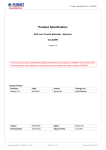
1
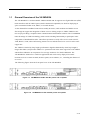
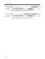
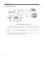
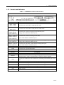
VX-MD4024 IP Digital Subscriber Line Access Multiplexer System Description Part Number A0-31-0128-2.1 Issue 2.1 Mandatory Regulations Mandatory Regulations The following sections describe the mandatory regulations that govern the installation and operation of the VX-MD4024 VDSL2 IP-DSLAM. List of Terms Table 1 lists the terms used in this chapter. Table 1 List of Terms Term Expansion CE Conformité Européenne EN European Standards FCC Federal Communications Commission ITU-T Telecommunication Standardization Sector of the International Telecommunications Union RoHS Restriction of Hazardous Substances General Requirements The sections that follow outline the mandatory regulations that govern the installation and operation of the VX-MD4024 VDSL2 IP-DSLAM. You must adhere to these instructions so that your system meets regulatory requirements. Prevention of Access The VX-MD4024 must be accessible only to authorized personnel. Install this apparatus in a restricted access location or similar environment to prevent unauthorized access. Laser Interface The VX-MD4024 uses Class I lasers as optical transmitter sources which are inherently safe unless mishandled. The radiation from laser diodes is much more intense than other light sources radiation. Only trained operating personnel thoroughly familiar with laser radiation hazards should install or remove the fiber optic cables and cards in this system. EMC Compliance EMC compliance may require the use of ferrites, shielded cables or other special accessories. Where required, these special accessories must be installed as per the instructions. I Mandatory Regulations Regulations compliance Safety Approval The system complies with the following safety norms: – Product Safety Requirements identified in EN60950:2000 – Over Voltage Protection Requirements of ITU-T K.20 EMI/EMC The system meets the requirements of Telecommunications Network Equipment: EN300-386. Electromagnetic Compliance The system complies with the standard FCC Part 15 Class A and EN55022. RoHS The system complies with the RoHS. CE The system conforms to the CE requirements. II Contents Contents Mandatory Regulations List of Figures ............................................................................................................................ IV List of Tables ............................................................................................................................... V Preface .......................................................................................................................................... 1 Scope ........................................................................................................................................ 1 Audience ....................................................................................................................................... 1 Related Documentation ................................................................................................................. 1 Documentation Conventions ......................................................................................................... 1 1 — System Description ........................................................................................................... 2 1.1 1.2 1.3 2 General Overview of the VX-MD4024 ............................................................................................ 3 1.1.1 Features ........................................................................................................................... 5 1.1.2 System Application ........................................................................................................... 6 Technical Summary of the VX-MD4024 ......................................................................................... 7 1.2.1 Physical Specifications ..................................................................................................... 7 1.2.2 Environmental Specifications ........................................................................................... 7 1.2.3 Power Specifications ........................................................................................................ 7 Detailed Description of the VX-MD4024 ......................................................................................... 8 1.3.1 Major Functional Block Diagram ...................................................................................... 8 1.3.2 Interface and Functionality Specifications ........................................................................ 9 1.3.3 Controls and Indicators .................................................................................................. 15 — Software Introduction ..................................................................................................... 16 2.1 General Overview ......................................................................................................................... 17 2.1.1 Features of Management Interface ................................................................................ 18 2.2 Configuration Management .......................................................................................................... 19 2.3 Performance management ........................................................................................................... 21 2.3.1 RMON Feature ............................................................................................................... 23 2.4 Fault Management ....................................................................................................................... 25 2.5 Cluster Feature ............................................................................................................................. 27 Abbreviations III List of Figures List of Figures Figure 1-1 VX-MD4024-1x0-DC with DC power and no splitter ............................................................... 3 Figure 1-2 VX-MD4024-1x1-DC with DC power and splitter .................................................................... 3 Figure 1-3 VX-MD4024-1x0-AC with AC power and no splitter ............................................................... 4 Figure 1-4 VX-MD4024-1x1-AC with AC power and splitter .................................................................... 4 Figure 1-5 VX-MD4024 system application ................................................................................................ 6 Figure 1-6 Major Functional Block Diagram (with Splitter)........................................................................ 8 Figure 2-1 Management Software Model ................................................................................................... 17 Figure 2-2 Cluster network topology – Daisy Chain .................................................................................. 27 Figure 2-3 Cluster network topology – Star ............................................................................................... 27 IV List of Tables List of Tables Table 1-1 VX-MD4024 Controls and Indicators ........................................................................................ 15 Table 2-1 RMON ETH Statistics variables ................................................................................................ 23 Table 2-2 RMON ETH History Control variables ..................................................................................... 23 V Preface Scope This document provides an overview on the VX-MD4024. It contains: Descriptive material about the DSLAM and its units (chapter 1) Descriptive material about the software of the DSLAM (chapter 2) Expansions of abbreviations used in the manual (Abbreviations) Audience The guide is intended for system engineers or operating personnel who want to have a basic understanding of the VX-MD4024. Related Documentation For information about installing, operating and maintaining, and troubleshooting the DSLAM, refer to the VX-MD4024 HW Installation and User Guide. For information about how to manage the DSLAM through Command Line Interface (CLI), refer to the VX-MD4024 CLI Command Reference. For information about how to manage the DSLAM through Web GUI, refer to the VX-MD4024 Web Configuration Tool Guide. Documentation Conventions The following conventions are used in this manual to emphasize information that will be of interest to the reader. Caution — The described activity or situation might or will cause service interruption. Note — The information supplements the text or highlights important points. 1 / 34 1 — System Description 1.1 General Overview of the VX-MD4024 1.2 Technical Summary of the VX-MD4024 1.3 Detailed Description of the VX-MD4024 2 / 32 1 — System Description 1.1 General Overview of the VX-MD4024 The VX-MD4024 is a rack-mountable VDSL2 IP DSLAM. It supports two Gigabit Ethernet (GbE) trunk interfaces and 24 VDSL2 ports (ADSLx backward compatible). Its ideal for deploying in space-constrained indoor areas, MDU, or external cabinets. As the demand for broadband connections steadily increases, cable modems and ADSL are not fast enough to support the integration of home services. Many people see VDSL/VDSL2 as the next step in providing a complete home-communication/entertainment solution. The VX-MD4024 takes advantage of VDSL2 technology with core IP switching functionality to participate in the competition of broadband last mile. This allows operators to easily offer services such as IPTV, VoIP, HDTV, VOD, videoconferencing, Internet access and advanced voice services at the same copper line. The VDSL2 is limited by loop length (performance degrades dramatically when loop length is longer than 300m.) and provides ADSL1/2+ operation mode in the same copper line with VDSL2 which allows industries to compensate for coverage weakness of a VDSL2 DSLAM. The VX-MD4024 is suitable for a small size application and can be easily deployed in remote locations such as a remote terminal, business parks, street cabinets, etc., extending the distance of its service. The following figures show the front panel view of the VX-MD4024. Figure 1-1 VX-MD4024-1x0-DC with DC power and no splitter Figure 1-2 VX-MD4024-1x1-DC with DC power and splitter 3 / 34 1— System Description Figure 1-3 VX-MD4024-1x0-AC with AC power and no splitter Figure 1-4 VX-MD4024-1x1-AC with AC power and splitter 4 / 32 1 — System Description 1.1.1 Features Highly compact solution that provides 24 VDSL2 only by 1U space and stackable for higher port density Scalable solution that allows new revenue to be generated with a minimum amount of installation time and expense Equipped with fan and air filters Low power requirements Full diagnostics and alarm reporting capability Standard-based with remote configuration and software upgradse to help service providers minimize daily operational costs Wide operating temperature range from -40 C ~ 65 C Provide two combo GBE trunk interfaces with both RJ-45 and SFP ports, and the priority for ° ° these two types of connectors (RJ-45 first or SFP first) is configurable Support Link Aggregation in IEEE 802.3ad that allows 2 GBE links to be aggregated together as a logical link. Supports both LACP protocol (dynamic) for load sharing and failover in case Ethernet link is lost Supports SNTP to automatically calibrate the time and date of the system Supporst on board thermal sensor to detect temperature conditions with software configurable thresholds that generate SNMP traps and syslog alarm entries Provide SSH (Secure Shell) for more secure remote operation Meet CE requirement 5 / 34 1— System Description 1.1.2 System Application Figure 1-5 VX-MD4024 system application The VX-MD4024 supports up to 24 VDSL2 lines per 1U box. It supports 802.3ad link aggression so that it extends the uplink bandwidth to 2 Gbps. It is also stack-able to provide higher port density. Users can manage the system with CLI/SNMP/Web GUI via in-band/out-band management channel. By enabling both GbE ports of VX-MD4024 for uplink traffic, a closed ring topology can be implemented, using spanning tree protocol (STP/ RSTP). 6 / 32 1 — System Description 1.2 Technical Summary of the VX-MD4024 1.2.1 Physical Specifications Item Value Width 431.8 mm (17 in.) not including the mounting brackets Height 44.45 mm (1U) Depth 265 mm (10.4 in.) Weight 4.1 Kg (DC power, with on-board splitter) 4.4 Kg (AC power, with on-board splitter) about 0.5 Kg less without splitter Rack mounting Standard 19” or 23” or ETSI rack 1.2.2 Environmental Specifications Item Value Operating Temperature DC: -40°C ~ 65°C AC: 0°C ~ 50°C Relative Operation Humidity 5% to 95% (non-condensing) at 35 C ° 1.2.3 Power Specifications Item Value Power Supply Interface Two options: DC: Dual A+B feeds, -36 ~ -60V, nominal – 48V AC: 100 ~ 240V (± 10% tolerance). Power Consumption: Max < 90 W, Typical < 75 W per 1U system 7 / 34 1— System Description 1.3 Detailed Description of the VX-MD4024 The VX-MD4024 uses Gigabit Ethernet interface for the uplink to the Ethernet Metropolitan Area Network (E-MAN). It transmits VDSL traffic between the subscriber equipment (router, bridge/modem or network interface card) and the E-MAN. 1.3.1 Major Functional Block Diagram Figure 1-6 Major Functional Block Diagram (with Splitter) The network processor provides the Layer-2 Ethernet function. Most of the board control are provided by processor including chip initialization, traffic processing and system management (OAM&P). As to the two GbE uplink (trunk) interfaces, the system can provide: 8 / 32 − Link Aggregation (802.3ad) − One of the GbE can be used as an uplink and the other can be used as a stacking interface − Provide Rapid Spanning Tree (802.1w) as a loop protection architecture 1 — System Description 1.3.2 Interface and Functionality Specifications Item Description Trunk Interface Supports both RJ45 and mini-GBIC (SFP) connectors for each uplink port (total 2 ports per box). Supports auto-selection between SFP and RJ-45 of Gigabit Ethernet interfaces with programmable priority. For RJ-45 interface: Supports IEEE 802.3 10/100/1000 Base-T auto-sensing GbE. And the selection of speed for each port is independent. Supports auto-adaptive between full-duplex and half-duplex operation modes for 10 and 100 Mbps operation speed on a per trunk port basis. The system only supports full-duplex mode for 1000 Mbps. For SFP interface: Supports 1000 Base-TX/SX/LX/EX/ZX/LHX interfaces (defined in IEEE 802.3z) depending on plug-in SFP transceiver Supports Ethernet frame that complies with IEEE 802.3z Line Interface General: Supports a total of 24 xDSL subscribers lines and supports provisioning of the operation modes (VDSL2, ADSL/ ADSL2+) with a default of VDSL2 on a per port basis. Handshake procedure of each DMT xDSL circuit complies with ITU-T G.994.1. Physical layer management of each DMT xDSL circuit complies with ITU-T G.997.1. xDSL subscriber interfaces support the following functions: Upstream and downstream non-overlapped mode Auto retrain Scrambling functionality FEC functionality Trellis coding Bit-swap Interleaving selection Target, maximum and minimum SRN margins programmable per port basis, independently for UP/DOWN directions Tx power adjustment while the SNR margin detected from the xDSL line exceeds the configured maximum SNR margin Support rate adaptation modes defined in ITU-T G.992.5 and Line Interface (continued) G.997.1 including Fixed (manually configured) and Adaptive At Init modes. xDSL subscriber interface is able to support Fast Channel or Interleaved Channel independently for each xDSL port. 9 / 34 1— System Description Item Description Supports Upstream Power Back-off (UPBO) while received power exceeds configured max-aggregation-PSD in the upstream direction. Supports detection of Dying Gasp message from xDSL CPE and indicate a CPE power loss alarm in the management interface. This is cleared upon the commencement of a retrain operation (i.e. when the CPE becomes active once more). Supports PSD shaping feature in VDSL2, ADSL and ADSL2+ Supports Downstream Power Back-Off (DPBO) for xDSL ports while operating in ADSL/2+ or VDSL2 mode VDSL2: VDSL2 functions comply with ITU-T G.993.2. Support Packet Transport Mode (PTM) per G.993.2 when operating in VDSL mode. Support provisioning the VDSL optional band types A, B and M (25K to 276K Hz) usage Supports VDSL OAM communication channels including IB (Indicator Bits) channel, EOC (Embedded Operations Channel), and VOC (VDSL Overhead control Channel). Supports selectable band plan A (profile 998, Annex A of G.993.2 and plan B (profile 997, Annex B of G.993.2) for each VDSL line on a per port basis. Line rate of a VDSL2 line port can reach symmetrical 100/100 Mbps or asymmetrical 100/50 Mbps at an ideal loop condition. Supports selectable spectrum profile of 8a/b/c/d, 12a/b, 17a, and 30a for frequency bands (Annex A, B and C) defined in G.993.2 when operating in VDSL2 mode. POTS Splitter Module (option) Compliant with ETSI TS 101 952-1-1 option A for European, ETSI TS 101 952-1-3 for Annex B European ISDN, or ANSI 600. The splitter/low pass filter is passive element. Even the system is loss of power (power supply fails), the POTS service is still OK. 10 / 32 Management Interface In-band management: provide all system OAM&P functions: software updates, configurations import/export, and management system interaction through trunk port. Out-band management: provide two kinds of management interfaces. One is the RS-232 local craft interface for basic provisioning. Interface default configuration: 9600 baud rate, 8-bit data, none parity, and 1 stop bit. The other is a 10/100 Base-T auto-sensing Ethernet Interface. OAM&P Configuration Management Performance Management Fault Management Status Monitoring. 1 — System Description Item Description Ethernet/IP Functionality Supports L2 bridge functionalities defined in IEEE 802.1d including: – Automatic source MAC learning – Static source MAC address table provisioning – Maximum 8K MAC addresses allowed to be learned into MAC table per system; 1 ~ 4095 MAC addresses per trunk bridge port with a limitation of maximum 4096 MACs for total number assigned to two trunk interfaces; 0 ~ 512 MAC addresses per line bridge port – Provision-able aging time for MAC address table with a default of 300 seconds on a per bridge port basis. The uplink and line bridge interfaces support Spanning Tree Protocol (STP) per IEEE 802.1D and Rapid Spanning Tree Protocol (RSTP) per IEEE 802.1w. VLAN – Supports IEEE 802.1q Port-based VLAN and Protocol- based VLAN – Supports 512 active VLANs simultaneously and the VLAN ID ranges from 1 to 4094 – Supports 2 layers VLAN stacking (“Q-in-Q”) – Supports VLAN translation – Supports port isolation functionality. When port isolation is enabled, no Layer-2 bridging between different ports (or subscriber lines) is supported in a VLAN – Supports static VLAN group and membership provisioning per bridge port basis – Supports configuring a port to be VLAN transparent (i.e., enabled for TLS) Multicast – Supports Multicast forwarding with IGMP v1 [RFC 1112], v2 [RFC 2236], v3 [RFC 3376], and Multicast MAC address mapping – Supports up to 512 concurrent IGMP groups (multicast channels) per system and a multicast channel has a maximum of 512 copies – Supports profile-based Multicast Access Control (up to 24 configurable profiles) and assign any profile to a subscriber interface (the maximum number of registered multicast channels within a profile is 512) – Able to limit the maximum number (0 ~ 20) of concurrent multicast groups to be joined per bridge port – Supports IGMP snooping/proxy in v1, v2, and v3 – Supports selection between IGMP proxy and IGMP snooping – Supports Fast and Normal Leave modes DHCP 11 / 34 1— System Description Item 12 / 32 Description – Supports DHCP Server (IP allocation to DSL users), DHCP transparent forward, and DHCP relay agent option-82 functionality (the value within Agent Circuit ID and Agent Remote ID sub-options are configurable). – Supports selection of DHCP forwarding modes with enabled relay option-82 (a) Normal Forwarding Mode: the system follows general MAC bridging mechanism for DHCP frame forwarding. (b) Secured Forwarding Mode: the system forwards DHCP frames according to attached Option-82 tags in downstream direction, rather than the destination MAC address of each DHCP frame. Able to pass through CDP (Cisco Discovery Protocol) message for both directions: between trunk ports and between DSL ports and trunk ports Supports Link Layer Discovery Protocol (LLDP) defined in IEEE 802.1ab that allows network devices to advertise and also recognize identities and capabilities within devices which are directly connected. This feature can be configured on a per port basis. Security – Supports ARP anti-Spoofing and MAC anti-Spoofing – Supports Layer-2 frame filtering based on source/destination MAC addresses – Supports Layer-3 filtering based on IP header including source/destination IP address, protocol ID, and TCP/UDP destination port number – Supports filtering out broadcast frames (destination MAC Address 0xFFFFFFFFFFFF) in the downstream direction. When this option is activated, only protocol-specific broadcasts (DHCP, ARP) are allowed to be forwarded to downstream users. – Supports secured forwarding that forces upstream traffic to the specific gateway, by means of replying upstream ARP request with MAC address of default gateway – Supports IEEE 802.1X Authentication using RADIUS protocol on each DSL port – Supports the ability of RADIUS Client for management access authentication whose identifier (username and password) can be authenticated by remote RADIUS Server QoS – Support Ethernet rate limit function including: a. Per bridge port rate limiting ü Profile based configuration ü Ingress: all kinds of traffic ü Egress: unicast traffic 1 — System Description Item Description – – – – – ATM and Interworking ü Apply to line bridge port b. Per bridge port per VLAN rate limiting ü Profile based configuration ü Ingress: all kinds of traffic ü Egress: unicast traffic ü Apply to line bridge port c. Per bridge port broadcast traffic rate limiting ü Profile based configuration ü Apply to line/trunk bridge port d. Per VLAN rate limiting ü Non-profile based ü Broadcast: support rate limiting for PVIDs of trunk interfaces with an internal maximum rate 500K bps per PVID VLAN ü Flooding: support rate limiting for all defined VLANs, trunk/line Supports Three Color Marking (TCM) rate limit policer in accordance with the Metro Ethernet Forum (MEF) Bandwidth Profile and RFCs 2697 & 2698. Supports VLAN priority queue per IEEE 802.1p (4 priority queues for 8 802.1p CoS value. The mapping between 4 priority queues and 8 priority values are configurable.) Supports selectable adopted priority queue mechanisms according to Strict Priority Queue (SPQ) and Weighted Fair Queue (WFQ) Supports traffic classification by re-assigning CoS (p-bit) value according to CoS (802.1p priority bit), VLAN ID, ToS, DSCP, Source/Destination IP address, or Source/Destination MAC address Configurable mapping between ATM PVC and 802.1p CoS for received untagged frame from subscriber port Supports 8 PVCs per subscriber line; VPI range is from 0 to 255 and VCI range from 32 to 65535 conforming to ATM Forum UNI 3.1/4.0, PVCs only. Supports multi-protocol encapsulation over ATM per RFC 2684 / RFC 1483 for bridged mode, LLC encapsulation method only. Supports AAL5 per ITU-T I.363.5. Commit the supported ATM service categories in the increasing order of UBR, CBR on a per port basis. Provide PCR (peak cell rate) configurable parameter for CBR service. Supports profile-based ATM traffic management (up to 16 traffic descriptors with one default and 15 user-configurable descriptors). Supports PPPoE transparent forwarding and PPPoE intermediate agent. 13 / 34 1— System Description 14 / 32 1 — System Description 1.3.3 Controls and Indicators Table 1-1 VX-MD4024 Controls and Indicators VX-MD4024 Front Panel LED Description SFP1 - LINK SFP2 - LINK To indicate the mini-GBIC trunk port link status SFP1 - ACT SFP2 - ACT To indicate the mini-GBIC trunk port data traffic status GBE1 - Speed GBE2 - Speed (LED on RJ-45) To indicate the electrical trunk port transmission speed (orange color LED on the Ethernet port) GBE1 - Link/Act GBE2 -Link/Act (LED on RJ-45) To indicate the electrical trunk port link status (green color LED on the Ethernet port) MGMT- Speed (LED on RJ-45) To indicate the transmission speed of the Ethernet management port (orange color LED on the Ethernet port) MGMT- Link/Act (LED on RJ-45) To indicate the link status of the Ethernet management port (green color LED on the Ethernet port) SYS To indicate the system operation status ALM To indicate the system alarm status DSL Status To indicate the link status of the subscriber lines. Interface GBE1/GBE2 MGMT CID HK / ALM Description Gigabit Ethernet trunk port 1/2 Ethernet Port connected to LAN for providing system out-band EMS/Telnet control interface, such as system monitor, control or software upgrade. RS-232 port connected to the terminal for monitoring and controlling the trunk card. RJ-50 connector for four housekeeping inputs and one alarm contact output. POTS RJ-21 connector (50-pin dual row header) for connecting POTS lines. LINE RJ-21 connector (50-pin dual row header) for connecting DSL lines. Button Description ACO Alarm Cut Off RST A hidden reset button for hardware resetting. 15 / 34 1 General Descriptopn 2 — Software Introduction 2.1 General Overview 2.2 Configuration Management 2.3 Performance Management 2.4 Fault Management 2.5 Cluster Feature 16 / 34 2 — Software Introduction 2.1 General Overview The software architecture of the VX-MD4024 is shown in the figure below. It can be divided into three layers: Management layer, OAM&P layer, and Firmware layer. Figure 2-1 Management Software Model As in the figure, CLI shell, SNMP agent, and WEB server are in the top-most layer (management layer) of the system software and offering OAM&P function of the DSLAM based on the conceptual management features as follows: Configuration Management Performance Management Fault Management The VX-MD4024 uses Flash memory as the database (DB) to store system configuration parameters, alarms and events. The firmware layer includes line card control drivers, Memory and I/O control, etc. 17 / 34 2 — Software Introduction 2.1.1 Features of Management Interface Supports CLI, SNMP (v1, v2c), and web-based GUI management interface through both in-band and out-band channels Supports up to 10 users accessing simultaneously for each management interface Supports out-band management via: - UART at full duplex line rate of 9600 bps (Craft port), 8-bit data, none parity, 1 stop bit - 10/100 Base-T auto-sensing Ethernet interface Supports Telnet interface for remote operators to login system operating console Supports in-band management of the unit via separate VLAN terminating on Network Processor; support prioritization of in-band management traffic Supports SNMP Management for SNMPv2, MIB I, MIB II and Enterprise MIBs including traps, sets, gets, and get next Supports UNIX syslog functionality per RFC 3164 (syslog messages are sent via UDP and the source port number is 1027) The IP address and subnet mask of the system for out-band management are provision-able with a default of 192.168.1.1 and 255.255.255.0. 18 / 34 2 — Software Introduction 2.2 Configuration Management The configuration management contains the following aspects: 1. System Setup, including setup for management IP address/IP routes, circuit setup (including to enable/disable/reset VDSL/ADSL circuit, query the administrative/operational status of a circuit, and bind profiles on a per port basis), GBE trunk interface setup, SNTP, IP routes, and user administration (including login authorization and provides three security levels). 2. Bridge Setup (see “Bridge Setup” below for more description) 3. VDSL/ADSL configuration (see “VDSL Configuration” below for more description) 4. Traffic Profile configuration, including traffic descriptor and priority queue mapping table 5. SNMP setup 6. System inventory and configuration information query The configuration management provides detecting and reporting to the operators through SNMP Trap for all memory updates reflecting changes in the system configuration. It also provides logging the changes in the operational state and making this information available (on-demand) to the operators over the operation interface. The system contains a database (DB) to store all the provisioning data so that the configuration can be restored in re-booting. Authorized operators can query the DB to obtain configuration data. Bridge Setup The bridge setup of the VX-MD4024 includes the following aspects: Interface setup, including Trunk/Line bridge port setup, Rate limit policer profile configuration and binding. VLAN configuration, including Trunk priority mapping, Static VLAN, Priority remark, VLAN Rate limit, VLAN translation, and Protocol Based VLAN. 802.1X Security configuration Spanning Tree Protocol configuration Filtering, including Filtering rule, ACL. Forwarding database DHCP/PPPoE configuration IGMP configuration Allowed IP filtering Anti-Spoofing configuration 19 / 34 2 — Software Introduction VDSL Configuration Configuration for a VDSL2 user port is provisioned by the parameter set, which is a group of attributes that determine the user port behaviors; also known as as the profile. The VX-MD4024 provides a profile-based provisioning per the definition of ITUT G.993.2 for VDSL line configuration data and a mechanism to associate the VDSL port to these profiles. One or more VDSL lines may be configured to share the parameters of a single profile. The VDSL profiles of VX-MD4024 include: Configuration Profile The parameters include Band Plan selection, Rate Adaptive Mode selection, Line Type, Max/Min data rate for fast/slow channel, Overhead data rate, PSD Mask, Maximum Tx Power, Max/Min/Target SNR Margin, Interleaving Max delay, Minimum impulse noise protection, Service Level Agreement data rate threshold, downstream PSD shaping type, parameters for Upstream Power Back-Off (UPBO), parameters for Downstream Power Back-Off (DPBO), Band Mask, Operation Mode, and etc. Alarm Profile This profile contains the TCA threshold values for near-end/far-end ESs, SESs, and UASs. The system provides up to 25 profiles. One of the profiles is a fix default that cannot be modified; users are allowed to create, delete, and edit the other 24 profiles. Each profile contains a parameter set for downstream and upstream direction respectively. Users can also observe the actual values of these parameters through CLI, Web-GUI, JG-2200, or EMS. The VDSL configuration also includes the function for user to query the line status, the channel interface status, and the failure state for VTU-C and VTU-R. The status information includes the attenuation rate, actual net data rate, the line attenuation, SNR margin, transmission power, actual interleaving delay, and etc. 20 / 34 2 — Software Introduction 2.3 Performance management Performance management supports performance monitoring by collecting and thresholding performance parameter counters against 15-miniute intervals for each interface and module respectively. Users can query the data of these parameters through CLI, Web-GUI, JG-2200 or EMS. Performance statistics include the following: 1. Statistics for current interval: A real-time aspect contains the reflection of the current value situation before the new interval. The current value includes values of current 15-min interval and current 1-day interval. 2. Statistics history at 15-minute basis: The system stores previous 96 statistics of PM parameters at 15-min interval for retrieving. 3. Statistics history at 1-day basis: The system stores previous 7 statistics of PM parameters at 1-day interval for retrieving. Most of the performance parameter thresholds are user-programmable. The VX-MD4024 uses a threshold crossing alert (TCA) to notify the management system when one of the counts during a measurement interval exceeds its threshold. The TCA contains the following information: – Specific interface involved – Error condition identifying the measurement type – Value of the parameter – Occurrence date and time of the event The performance management also provides the traffic counter including transmitted packets, error packets and discarded packets for each interface (network and subscriber interface) in both transmit and receive direction. Users can observe these data through CLI, Web-GUI, JG-2200 or EMS. The VX-MD4024 provides the following thresholds for the PM statistics, and all these thresholds are configurable: NE threshold FE threshold 15min ES threshold 15min ES threshold 15min SES threshold 15min SES threshold 15min UAS threshold 15min UAS threshold 24hour ES threshold 24hour ES threshold 24hour SES threshold 24hour SES threshold 21 / 34 2 — Software Introduction 24hour UAS threshold 24hour UAS threshold Ethernet PM The VX-MD4024 provides Ethernet performance statistics of transmitted packets, error packets, discarded packets, etc. on each bridge Interface. xDSL PM The VX-MD4024 provides the following xDSL PM parameters: Parameter 22 / 34 Description LOF Loss of Frame Count LOS Loss of Signal Failure Count LOSS Loss Of Signal seconds LOPRS Loss Of Power seconds (only for VTUR) ESS Errored Seconds SESS Severely Errored Seconds UAS Unavailable Seconds Inits Modem Failed Initialization events (only for VTUC) Fixed Octets(Fast) Count of corrected octets for fast channel. Bad blks(Fast) Count of uncorrectable blocks for fast channel. Fixed Octes(Slow) Count of corrected octets for slow channel. Bad blks(Slow) Count of uncorrectable blocks for slow channel. 2 — Software Introduction 2.3.1 RMON Feature The VX-MD4024 supports performance statistics defined in RMON MIB groups 1 (Ethernet statistics), 2 (history control), 3 (alarm), and 9 (event) per RFC 2819 for all network uplink 10/100/1000 ports. The supported parameters are as follows: Table 2-1 RMON ETH Statistics variables Variable Description DropEvents Monitoring Rx dropped packets Octets Monitoring Rx bytes packets Pkts Monitoring Rx packets BroadcastPkts Monitoring Rx broadcast packets MulticastPkts Monitoring Rx multicast packets CRCAlignErrors Monitoring Rx error alignment packets UndersizePkts Monitoring Rx undersize packets OversizePkts Monitoring Rx oversize packets Fragments Monitoring Rx fragments packets Jabbers Monitoring Rx jabber packets Collisions Monitoring Tx single collision packets Pkts64Octets Monitoring Tx 64 octets Pkts65to127Octets Monitoring Tx 65 to 127 octets Pkts128to255Octets Monitoring Tx 128 to 255 octets Pkts256to511Octets Monitoring Tx 256 to 511 octets Pkts512to1023Octets Monitoring Tx 512 to 1023 octets Pkts1024to1518Octets Monitoring Tx 1024 to 1518 octets Table 2-2 RMON ETH History Control variables Variable Description HistoryDropEvents Monitoring Rx dropped packets HistoryOctets Monitoring Rx bytes packets HistoryPkts Monitoring Rx packets HistoryBroadcastPkts Monitoring Rx broadcast packets HistoryMulticastPkts Monitoring Rx multicast packets HistoryCRCAlignErrors Monitoring Rx error alignment packets HistoryUndersizePkts Monitoring Rx undersize packets HistoryOversizePkts Monitoring Rx oversize packets HistoryFragments Monitoring Rx fragments packets HistoryJabbers Monitoring Rx jabber packets 23 / 34 2 — Software Introduction 24 / 34 HistoryCollisions Monitoring Tx single collision packets HistoryTxBytes Monitoring Tx bytes HistoryTxPackets Monitoring Tx packets HistoryTxMulticast Monitoring Tx multicast HistoryTxBroadcast Monitoring Tx broadcast HistoryUtilization Monitoring Tx Utilization 2 — Software Introduction 2.4 Fault Management Fault management is conceptually partitioned into two levels: the system top level, and interface-specific level. Both levels are alarm-level configurable and can be Major and Minor. All the alarms are mask-able. Fault management provides the alarm output through hardware output interface (on the system front panel) and visible indicator (LED). The alarm/status indications are automatically generated as a result of certain events/conditions. The VX-MD4024 supports query of all current alarm status. It is also able to keep 256 records of historical alarms and events respectively. System Alarms The VX-MD4024 provides the following System alarms: Alarm Name Description SYS_HOUSEKEEP1 House Keeping 1 SYS_HOUSEKEEP2 House Keeping 2 SYS_HOUSEKEEP3 House Keeping 3 SYS_HOUSEKEEP4 House Keeping 4 SYS_FAN Fan Error SYS_SELFTESTFAILED Self Test Failed SYS_ABOVETEMP Temperature Above Threshold SYS_BELOWTEMP Temperature Below Threshold SYS_PIV Product Identification Violation GBE_LOS Gigabit Ethernet Loss of Signal Cluster_MasterDuplication Cluster has duplicate Master (two Masters exist) Cluster_MasterOutOfCapacity Cluster is out of capacity Cluster_HostUnmanaged Cluster node enter unmanaged state 25 / 34 2 — Software Introduction xDSL Alarms The VX-MD4024 provides the following alarms for VDLS/ADSL interface: Alarm Name Description XDSL_LOF XDSL Loss Of Framing XDSL_LOS XDSL Loss Of Signal XDSL_LOSQ XDSL Loss Of Signal Quality XDSL_LOL XDSL Loss Of Link XDSL_INIT_FAILURE XDSL Init Failure XDSL actual data rate is less than the configured Service Level Agreement threshold for downstream direction XDSL actual data rate is less than the configured Service Level Agreement threshold for upstream direction XDSL_BELOW_SLA_DS XDSL_BELOW_SLA_US XDSL_ESE XDSL Excessive Severely Errored Seconds XDSL_NCD_SLOW XDSL No Cell Delineation on the slow channel XDSL_LCD_SLOW XDSL Loss of Cell Delineation on the slow channel XDSL_NCD_FAST XDSL No Cell Delineation on the fast channel XDSL_LCD_FAST XDSL Loss of Cell Delineation on the fast channel XDSL_LOF_FE XDSL Far End Loss Of Framing XDSL_LOS_FE XDSL Far End Loss Of Signal XDSL_LPR_FE XDSL Far End Loss Of Power Failure XDSL_LOM_FE XDSL Far End Loss Of Margin XDSL_NO_PEER_VTU_PRESENT_FE XDSL Far End No Peer Vtu Present 26 / 34 XDSL_ESE_FE XDSL Far End Excessive Severely Errored Seconds XDSL_NCD_SLOW_FE XDSL Far End No Cell Delineation on the slow channel XDSL_LCD_SLOW_FE XDSL Far End Loss of Cell Delineation on the slow channel XDSL_NCD_FAST_FE XDSL Far End No Cell Delineation on the fast channel XDSL_LCD_FAST_FE XDSL Far End Loss of Cell Delineation on the fast channel 2 — Software Introduction 2.5 Cluster Feature The VX-MD4024 supports Cluster feature that can make a group of NEs (network elements) work together as a single NE from the management point of view. Operators can manage the NEs in a cluster, called cluster nodes, via the same single IP address in terms of CLI, Web-based GUI or SNMP based management interfaces. Currently, a VX-MD4024 cluster can include up to sixteen cluster members (NEs). There is one Master and the other members are all Slaves in a cluster. The Master works as a gateway of the Slaves, and it also can forward CLI/Web/SNMP commands to the destination Slave. The Slaves can execute the commands and respond to the Master. There are two possible network topologies for conducting a Clustering Management group: Daisy chain and Star. PC (out-band management) Master Slave Bitstorm-HP Bitstorm-HP GBE Uplink Slave GBE GBE User link Uplink Bitstorm-HP GBE GBE GBE User link Uplink User link E-MAN PC (in-band management) Figure 2-2 Cluster network topology – Daisy Chain Master Slave Bitstorm-HP GBE Bitstorm-HP GBE Uplink Uplink Slave Bitstorm-HP GBE Uplink LAN GBE uplink Figure 2-3 Cluster network topology – Star Before you group a Master and a Slave IPDSLAM, some parameters need to be well configured: 27 / 34 2 — Software Introduction 1. Cluster domain name: The group name for a cluster. Must be the same on Master and Slaves within a cluster group. 2. Cluster IP address: IP address to be used for remote management when Master and Slave are grouped together. Only one IP address is required for Master/slaves management within a cluster group. 3. NE cluster name: A unique name to identify the NE (Master or Slave) in a cluster group. 4. Set private IP address on in-band port for both Master and Slave IPDSLAM. The private IP is used for communication between Master and Slave. The management center actually uses Cluster IP address for remote management. 5. Master and Slave need to be configured with same management VLAN. 6. The default gateway should be configured to the router that is aware how to route management traffic to Management Center of the management network. The setting of Cluster default gateway should be the same between Master and Slave. 28 / 34 Abbreviations ADSL asymmetrical digital subscriber line ADSLx ADSL/ADSL2/ADSL2+ ANSI American National Standards Institute ATM asynchronous transfer mode CLI command line interface DSLAM digital subscriber line access multiplexer EMS element management system DSL digital subscriber line EMC electromagnetic compatibility EMI electromagnetic immunity ETSI European Telecommunications Standards Institute Mbps megabit per second LED light emitting diode POTS plain old telephone service PSTN public switched telephone network PVC permanent virtual circuit SNMP simple network management protocol UNI user-network interface VDSL very high speed digital subscriber line 29 / 34 30 / 34