1
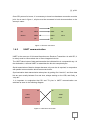
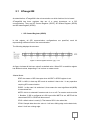
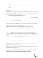
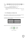
BACHELORARBEIT Technikum Wien - Degree Program: Informations- und Kommunikationssysteme Connecting an Arduino UNO to KNX By: Leticia Vizán Tundidor Student Number: ic14x001 Supervisor: Mag. DI Friedrich Praus Wien, 26/01/2015 Declaration „I confirm that this paper is entirely my own work. All sources and quotations have been fully acknowledged in the appropriate places with adequate footnotes and citations. Quotations have been properly acknowledged and marked with appropriate punctuation. The works consulted are listed in the bibliography. This paper has not been submitted to another examination panel in the same or a similar form, and has not been published. I declare that the present paper is identical to the version uploaded." Vienna ,26/01/2015 Place, Date Signature 1 Table of Contents 1 2 3 4 5 Introduction ............................................................................................................ 3 1.1 Motivation ....................................................................................................... 3 1.2 Scope of work ................................................................................................. 3 1.3 Outline ............................................................................................................ 3 1.4 Serial Communication ..................................................................................... 4 1.4.1 SPI communication .................................................................................. 4 1.4.2 UART communication ............................................................................. 5 Arduino UNO ......................................................................................................... 6 2.1 ATmega328 .................................................................................................... 7 2.2 SPI software on Arduino Uno .......................................................................... 9 2.3 UART software on Arduino Uno .................................................................... 11 KNX protocol ....................................................................................................... 13 3.1 Protocol definition ......................................................................................... 13 3.2 Characteristics .............................................................................................. 13 3.3 Group Address ............................................................................................. 15 BIM 13x ............................................................................................................... 16 4.1 SPI software on BIM13x ............................................................................... 16 4.2 UART software on BIM13x ........................................................................... 17 Arduino Uno and BIM135 board connection. ........................................................ 19 5.1 SPI hardware connection. ............................................................................. 19 5.2 UART hardware connection .......................................................................... 20 6 Communication protocol between Arduino and BIM ................................................. 22 7 8 6.1 Communication protocol over SPI ................................................................. 22 6.2 Communication protocol over UART ............................................................. 23 Proof of concept................................................................................................... 24 7.1 Arduino Uno Code ........................................................................................ 32 7.2 BIM 13x Code ............................................................................................... 32 7.3 Function modes ............................................................................................ 32 7.4 Results ......................................................................................................... 43 Conclusion ........................................................................................................... 45 A Abbreviation ........................................................................................................... 46 B Bibliography............................................................................................................. 47 2 1 Introduction The project outlines the communication between a BIM board, which supports KNX, and a second microcontroller, which is an Arduino UNO. Two ways of communication are supported: SPI and UART communications. 1.1 Motivation The motivation for this project is to develop the communication between Arduino to KNX. The aim is to know the value of the different modules implemented for other students. The data is sent from KNX and then collected via Arduino Uno. It is also possible send data from Arduino to KNX for changing the value of the communication object. 1.2 Scope of work The scope of this project is to implement communications between a BIM 132 board (which supports KNX) and another microcontroller, which for this project was Arduino UNO. The final goal is to be able to dispatch data to Arduino UNO from a BIM board and vice versa. This data contained information about the value of the object communication (related to different measures as lights, temperature, humidity…).; which when changed resulted in a change of the corresponding value. Depending on the requirements, two protocols of communication can be used. One based on SPI communication or the other based on UART communication. 1.3 Outline The thesis will start with a short introduction about SPI and UART communications, followed by details about Arduino UNO and its communication. All internal registers required for the communication and how to implement it are specified. Before going into a description of the BIM board, KNX protocol is broadly explained. After that communication over the BIM board is also explained. The hardware connection between both boards defined, as well as the protocol created, will also be explained. 3 1.4 Serial Communication The main difference between a synchronous interface (as SPI) and an asynchronous one (as UART) is the way in which synchronization information is sent from transmitter to receiver. The synchronous peripherals need a physical line (cable) dedicated to the clock signal, providing synchronization between the two devices. Asynchronous peripherals do not use a clock signal; the synchronized information is extracted from the same data. Start bit and stop are added, as well as a precise format for a fixed transfer rate. 1.4.1 SPI communication SPI is the acronym of Serial Peripheral Interface. information between two or more integrated circuits. It is mainly used to transfer SPI is a full-duplex synchronous protocol. This indicates that data can be sent and received simultaneously. The bus interface of serial peripheral or bus SPI is a standard to control almost any digital electronic device which is able to accept serial bit stream controlled by a clock. SPI consists of a clock, data incoming, data outgoing and a selected pin, which enable or disable the communication between both devices. Several SPI-compatible devices can share communication wires however each device must have its own chip select line. When SPI communication starts, master microcontroller has complete control of it and is able to settle SPI communication with the slave required. That means that slave devices only can communicate when master allows it. The lines of the SPI data communication are the following: Master In/Slave Out (MISO): this line is the input of the master microcontroller and also the output of the slave microcontroller. Master Out/Slave In (MOSI): this line is the output from the master microcontroller and also the input to the SPI slave. Serial Clock (SCK or SCLK): the line is the serial clock line. This line designates when data on the MISO and MOSI are valid. Slave Select (SS): is the “chip select” line. There is one for each SPI device. The master microcontroller imposes the SS line, for when the device wants to communicate; the signal has to be turned to low. When the signal of this pin is high the slave device will not respond to any SPI communication on the other three pins. 4 [1], p.261 Once SPI protocol is known, it is necessary to know how hardware connection must be joint. As we see in figure 1, all pins must be connected in both microcontrollers to the same pin name. CLK CLK SPI MOSI MOSI SPI Master MISO MISO Slave /SS /SS Figure 1: SPI wire connection 1.4.2 UART communication UART is the acronym of Universal Asynchronous Receiver Transmitter. As with SPI, it is mainly used to communicate two or more integrated circuits. The UART takes bytes of data and transmits the individual bits in a sequential way. At the destination, a second UART re-assembles the bits into complete bytes. Serial transmission of data is cheaper because only one wire is required, in comparison with parallel communication which uses several wires. Synchronization data transmission takes place by putting first “start bit”, and then data bits are sent usually between five and nine, always starting on the LSB, and finally, a “stop bit”. It is important to emphasize that RX and TX pins in UART communication are switched as seen in the following diagram. RX RX UART UART Master Slave TX TX Figure 2. UART wire connection 5 2 Arduino UNO Arduino UNO specification can be found on the official web site of Arduino. In the below diagram, the main features are represented. Figure 3. Arduino Board Microcontroller ATmega328 Operating Voltage 5V Input voltage (recommended) 7-12 V Input Voltage (limits) 6-20 V Digital I/O Pins 12 (of which 6 provide PWM output) Analog Input Pins 6 DC Current per I/O Pins 40 mA DC current for 3.3V Pin 50 mA Flash Memory 32 KB (ATmega328) SRAM 2 KB (ATmega328) EEPROM 1 KB (ATmega328) Clock Speed 16 MHz Table 1. Arduino Uno main characteristics [3] 6 2.1 ATmega328 As stated before, ATmega328 is the microcontroller on which Arduino Uno is based. ATmega328 has three registers that are of a great importance on a SPI communication. They are SPI Control Register (SPCR), SPI Status Register (SPSR) and SPI data Register (SPDR). SPI Control Register (SPCR) In this register, all SPI communication configurations are specified, each bit representing a different field of the communication. The following displays the structure: Figure 4. SPCR register structure. [4] p. 173 As figure 4 shows all bits have value 0 as default value. When SPI is used this register has different values, depending if it is in slave or master mode. -Master Mode: SPIE: the reason of SPI interrupts when bit SPIF in SPSR register is set. SPE: is HIGH, in that way SPI mode is enabled. It has to be 1 in any operation requiring SPI communication. DORD: In this case it is settled as 0, that means the most significant bit (MSB) is transmitted first. MSTR: this bit is selected if master mode is on or off. For master mode must be 1. Besides, if /SS is configured at LOW input while MSTR is set, MSTR will be cleared and SPFI in SPSR will become set. CPOL: default value is used (0). That means SCK is low when idle. CPHA: Sample data when the value is 1 will set a falling edge on the data clock, when 0 it will set a rising edge. 7 SPR1 and SPR2: these bits control the SCK rate on the microcontroller configured as master (they have no effect on the slave). It is left as default value (0 0). -Slave Mode: As most parts of the registers stay in the same state when in master mode, to assure that communication protocol is working in the same ´language´. In slave mode only changes from master mode will be explained. MSTR: slave mode is defined when the bit value is 0. [4], pp. 173-174 SPI data Register (SPDR) In this register data (1 byte) is saved, so it can be said that this register could be used as a buffer. It is possible to read and write on it. Data is read from this register, because when data is sent it is saved on here. Before data is sent, users have to be careful of the way that transmission is configured, because as can be seen in figure 5, 0-bit is LSB and 7-bit is MSB. Figure 5. SPDR register structure. [4] p. 174 SPI Status Register (SPSR) This register indicates information about the transmission state. registers explained, all bits default value are 0. As in previous Although it is an 8-bit register, five of these bits are non-care state, which means that it is not important if the value is 0 or 1. As figure 6 shows, bits 7 and 6 only have read permission. This is due to the fact that depending on the state of the transmission, bits will be represented in one way or another, and memory changes them when a particular event happens. 8 Figure 6. SPSR register structure. [4] p. 175 Three bits of interest are analyzed in the following. SPIF: when serial transfer is complete, SPI flag is set. WCOL: sets when read and write actions in SPDR register try to access at the same time [4], pp. 175 2.2 SPI software on Arduino Uno Arduino contains in its hardware more than one way to implement SPI communication. As only Arduino Uno is used in this project, this will be the only reference. It is possible to develop SPI by digital pins. In the following table the pin and its function on SPI communication are referenced. SPI function Arduino Uno Pin MOSI 11 MISO 12 SCK 13 SS (slave) 10 Table 2: Arduino Uno SPI pins list. Otherwise ICSP connector can be used to implement SPI communication. Figure 7: ICSP header. 9 Master-Slave communication Master mode is supported by a specific Arduino library, so it has to be included in all code related to the SPI protocol. #include <SPI.h> The following configuration could be changed by the next function calling, or by changing the registers specified in paragraph 2.1. Besides the order in which the bits are received it is important. Two ways are possible MSBFIRST (most significant bit first) or LSBFIRST (less significant bit first). This can be specified by inserting the next function: SPI.setBitOrder() If it is not inserted, it is the most significant bit as default. That is the specification selected in this project. It is possible to set data mode as well. This means the polarity and phase of the clock. This is made by inserting the next function: SPI.setDataMode() Four modes are possible, but in this project default value is used, that means that the clock is normally low and that the data is read in the transmission from low to high. SPI.setClockDivider() This configuration is specified on the EEPROM memory datasheet (see table 4). And as can be seen MOSI, SCK and /SS must be inputs. However MISO has to be defined by the user. It will be defined as output. PIN Direction, Master SPI Direction, Slave SPI MOSI Output Input MISO Not defined User Defined SCK Output Input /SS Output Input Table 3. SPI Pin Overrides [4] p. 168 10 2.3 UART software on Arduino Uno In the case of Arduino UNO there is only one available UART and it is duplexed to the USB serial communication that is used for communicating to a computer, mainly for programming and debugging. The derivate problem of this is that some collisions can appear when the sketch is been debugged and the UART connection with another electronic device (in our case the BIM board) wants to be used. In this case the connection between RX and TX pin could be as is shown in the following figure. Figure 8. Colliding UART communication lines [16] pp.227 The diagram above shows what would happen if both connection, the BIM board and the computer, tried to transmit data to the Arduino at the same time. Due to this situation, it is determined that Arduino cannot be programmed nor talking to the computer while BIM is connected to the Arduino´s serial port. To avoid this problem it was determined that a way around this, could be unplugging the BIM shield every time Arduino need to be programmed. [16] pp.226-227 Another possibility is to create a new software serial port. For that task <SoftwareSerial.h> library must be referenced. The utility of this strategy is to declare another two pins which now will be able to support the UART communication. By using this, the collision is solved due to pin 0 and 1 (shared to the USB) are used to communicate Arduino to a computer and the new ones, in this case, to communicate Arduino to BIM. 11 Using those new UART pins are not that much more complicated, you only have to switch in all calls “Serial” for the name assigned to the new pin’s communication, In this case it is “mySerail”. So, if the function calls to communicate Arduino to a computed is Serial.begin(…), the function call to communicate Arduino to BIM is mySerial.begin(…). In the following table it is referenced the pin and its function on UART communication to BIM. UART function Arduino Uno Pin RX 5 TX 6 Table 4: Arduino Uno UART pins list. For making UART communication supported on Arduino Uno, no library has to be included (in SPI had to be included). For making UART communication work, firstly, the speed of transmission must be declared. This speed is represented in terms of bits per second (baud). For communicating in this project 9600 bauds are used. As default is set: 8 data bits, no parity, and one stop bit. For this it is necessary to include in the sketch the following function call: Serial.begin(speed); When read on UART bus is necessary, the predefined function for that can be used. This function returns the first byte of incoming serial data available, or -1 if there are no data available. Serial.read(); Besides this it is useful to know when Arduino is receiving data. For this task the next function can be inserted. This function returns the number of bytes available to read. Serial.available(); When it is necessary to write another function, it is predefined as well. The following function prints data to the serial port on the base specified (format). Values permitted are BIN(binary), OCT(octal), DEC (decimal),HEX(hexadecimal). When it is inserted as print (), it returns the number of bytes written, though reading that number is optional. Serial.print (data, format); There is an improvement of the previous function. It reachs the same characteristics as Serial.print (), but also prints a carriage return character (‘\r’) and a newline character (‘\n’). This function is Serial.println (data, format); 12 3 KNX protocol 3.1 Protocol definition A protocol is communication rules that permit information flows between equipment. Normally these rules are classified as public or private. In this case KNX is an open protocol to which everyone can access. It is essential that if two or more devices have to be communicated, they have to “speak the same language”. KNX is a standard protocol because all its elements in the installation use a common protocol to communicate. And it is worldwide because there are more than 120 country partners. “KNX Association is the creator and owner of the KNX technology – the worldwide STANDARD for all applications in home and building control, ranging from lighting and shutter control to various security systems, heating, ventilation, air conditioning, monitoring, alarming, water control, energy management, metering as well as household appliances, audio and lots more. The technology can be used in new as well as in existing home and buildings. “ [5] In KNX system data transmit is done through a cable or bus connected to all devices. The bus allows all components on home automation installation to be communicated, in this way it is possible that any component can control another, independent of the location or length between them. 3.2 Characteristics KNX-EIB has 321 members in 34 countries. [5] KNX uses a bus typology, that means KNX installation (figure 11) has some advantages over any conventional connection (figure 10). The most remarkable benefit is that using KNX the energy consumption can be reduced thanks to illumination and heating, besides controlling the most consuming peaks of energy costs can be reduced. Also, planning the installation on KNX communication makes it possible to reduce cabling. Besides this it is simpler to introduce some changes or even expand the installation. 13 It is also important that KNX association assure 100% compatibility of equipment. Figure 10. Conventional installation Figure 11 .KNX installation As can be seen in the image above, KNX protocol has a distributed topology. This type of system does not have a central unit. Every unit is smart and knows what to do. This makes the system more reliable because if one unit fails, it does not affect the other units and the system can keep working. [8] p.10-11 14 KNX also can be implemented on diverse transmission media, each media can be used in combination with others. These medias are: Twisted Pair (TP), Power Line (PL), Radio Frequency (RF) and Ethernet (IP). [5] In this project the communication media used is twisted pair. - Twisted Pair (TP-1) In this media KNX has a transmission speed defined as approximately 9600 bits/s. All products works on the same bus, thats the way they exchange information. Twisted pair is used to power devices and to transfer information, but it is not available to power controlled devices as it can be with lights, heating and so on. Therefore there has to be a connection to electricity grids. 3.3 Group Address It can be considered as a virtual wired among system components. When a sensor and an actuator are required to make a function the same group address is assigned to both of them. It does not exist strong rules about it; except that maximum numbers or addresses are 28.000. The structure followed in this project is the one referenced as three-level addressing. M M M M M Mi Mi Mi S S S S Main group 5 bit: 0 - 31 S S S S Subgroup Middle group 8 bit : 0 - 255 3 bit: 0 - 7 Figure 12. Group Address: 3 levels - Main Group: functional area, basically make reference to the full installation (e.g. 1=First floor, 2=second floor....) Middle Group: function inside that area (eg.0= lights, 1=blinds, 2=heating...) Subgroup: load or group of loads (e.g. 09= kitchen light, 20=living room heating) Actuators can listen to several group addresses, as well as having several group addresses. Sensors however can only send one group address per telegram. [7] p.6-7 15 4 BIM 13x The board programmed is an evaluation board (EVB) that contains different debuggers depending of the microcontroller which want to be programmed. 4.1 SPI software on BIM13x The BIM board has a SPI communication as a feature of the controller. On the hardware side, the board has a pin which plays the role of Clock on SPI communication and pins which play the role of MOSI, MISO. For the Slave Selected pin any digital I/O could be use, in this case pin 7 on Port7 will be used. [14] p.4 Concerning the software side, there are mainly two defined functions regulating SPI communication. The first function initializes the driver for transmitting data over SPI. It has the following format: void SPIInit (enum SPISpeed speed, BYTE CKDAP, BOOL MSBFirst) Where: - enum SPISpeed speed: has the value SPI_BAUD_9600, which indicates SPI communication will have a speed of 9600 bauds. - BYTE CKDAP: in this case has the value 0x00 which indicates clock is idle high; data is valid if clock is high. - BOOL MSBFirst: has the value TRUE, which means the first bit transmitted is the most significant one. [13 ]p.24 The second one is the function used to send and receive data over SPI bus. It has the following format: BOOL SPISend (BYTE* pData, BYTE length) Where: BYTE* pData: is a pointer that data wants to be transmitted over SPI and where received data is stored. - BYTE length: number of bytes sent over SPI This function returns true is the exchange was successful and false if it was not. [13] p.24 16 4.2 UART software on BIM13x For programming UART0 on the BIM board, there exists no predefined function as happens on SPI. Instead it is necessary to know the register of the NEC78K0 /KE2 microcontroller used by this kind of serial communication. BRG0 The Baud rate of the transmission is specified as the modified register BRGC0 in NEC78K0 /KE2 microcontroller. The aim is to have a baud rate of 9600 bauds. Because this is the typical Arduino Uno speed. Figure 13. BRGC0 register in NEC78K0 /KE2 microcontroller [17] p. 438 The aim is to have a baud rate of 9600 bauds. It is known that hardware information such as fPRS=9,830,400 Hz. We select: - TPS01 =1; TPS01 =1; That means fPRS has to be divided by 25 -> fXCLK0= fPRS/25 = 307,200 Hz. Now a parameter “k” is determined by bits MDL04, MDL03, MDL02.MDL01, and MDL00. So the value selected is 10000 which gave us k=16. This means fXCLK0 has to be divided by 16. With a result of 19,200 Hz. As it is said on the datasheet: “the baud rate value is the output clock on the 5-bit counter divided by 2” Finally, we have a 9600 bits/s as baud rate value. The register BRGCO has the value 11010000 in binary, which is 0xD0 in hexadecimal which is the one to put in the function FT12Init (…); [13] p.18 && [17] p.438-439 17 ASIM0 By this register the UART communication can be configured: Figure 14. ASIMO register in NEC78K0 /KE2 microcontroller [17] p. 436 Where: - POWER0: the value 1 is set, so enables the clock on the UART. It is necessary if activating UART is desired. - TXE0: the value 1 enables the transmission. 0 disables it. - RXE0: the value 1 enables the transmission. 0 disables it. - PS01 AND PS00: define the parity of the received and transmit data. For no parity PS00=0 and PAS01=0. - CL0: 1 set 8 bit per character. 0 set 7 bits. - SLO: 1 set 2 stop bits, 0 set 1 stop bit. So, finally our register ASIMO has the value 11100101 in binary, and 0xE5 in hexadecimal which is the one to insert in the function FT12Init (…); [13] p.19 && [17] p.436-439 TXS0 This 8-bit register is used to transmit data. When this register is complete the transmission begins and data is sent over pin 14. It is an only-read register. RXB0 When the register RXS0 is full by the data received over pin 10, data are copied to register RXB0 because RXS0 is an only-write memory, and users cannot have access to it. 18 5 Arduino Uno and BIM135 board connection. In this paragraph the proper way to connect both boards physically will be discussed. 5.1 SPI hardware connection. SPI hardware connection has to be done as specified in figure 1. . BIM 13x GND (pin 24) MOSI (pin 14) MISO (pin 10) CLK (pin 16) BIM 135 SS (pin 7) Digital I/O Figure 15. Wire connection between BIM board and Arduino 19 Wire connections must be done paying special attention to connect MISO pin in Arduino Board with MISO pin in BIM135. Once each datasheet is examined, it would not be difficult to find the correct connections. Basically connections have to be done on the same way that were specified in paragraph one (SPI connection) especially on figure 1. SPI wire connection. SPI pin Arduino Uno BIM135 MOSI 11 14 MISO 12 10 SCK 13 16 /SS 10 7 GND GND 24 Table 5. Pins connections between Arduino and BIM board on SPI communication. 5.2 UART hardware connection Proceeding in a similar way than in SPI connection: SPI pin Arduino Uno BIM135 RX 11 10 TX 12 14 GND GND 24 Table 6. Pins connections between Arduino and BIM board on UART communication. 20 . BIM 13x GND (pin 24) TX (pin 14) RX (pin 10) BIM 135 Digital I/O Figure 16. Wire connection between BIM board and Arduino 21 6 Communication protocol between Arduino and BIM 6.1 Communication protocol over SPI Essentially, communication between the BIM board and Arduino has as goal exchange information about state changes of different Group of Communication. For making this communication understandable for both parts, it is necessary to create a protocol to regulate the flow and interpretation of the information. To create Protocol is simple. It´s based on send data on acknowledgement. Sequence diagram: BIM 13X Arduino UNO Command ACK Object ACK num_bytes ACK Value of the object ACK Time Figure 17. Sequence diagram of the communication protocol. By seeing the figure above, we can appreciate that the logic of the protocol is quite simple. Basically at least four bytes are sent over SPI bus. Firstly a command that specifies to Arduino what to do with the following data sent. Secondly, the data exchange specifies the identifier of the group of communication object that changed its 22 value. Then, the number of bytes that the value of the group of communication has. Finally, Arduino know the value of the group of communication right before being received. After every data received, Arduino makes known to the BIM board that data was well received by sending an acknowledgement message (defined as 0x01 on the protocol) back. This acknowledgement message is dispatched after receiving new data. In this way the BIM board knows data already sent was well received and can proceed to send the next one. Command Object Num_butes Value_Object 1 byte 1byte 1byte 1bye Figure 18. Data sent over SPI 6.2 Communication protocol over UART Basically this protocol works the same way as the protocol for SPI. The change is that the acknowledgment now is not sent back. There are two modes, write and read, basically, both protocols have the same structure but in different ways. BIM 13X Arduino UNO Command ACK Object ACK num_bytes ACK Value of the object ACK Figure 19. Sequence diagram of the communication protocol over FT12. Time 23 7 Proof of concept Physical connection between BIM board and PC BIM M13x (bus interface module) is a module composed of a microcontroller NEC78K0 / Kx2 containing in its memory API to communicate the KNX bus transceiver associated with a TP-UART. The transceiver will fit the voltage levels between the card and the KNX bus. BIM M13x modules comply with the KNX specification. The evaluation board is programmed via the intermediary of MINICUBE2 from the IAR Embedded System software. This allows the application developer to use the IAR tool, which includes powerful debugging tools. All these development tools have been installed on a virtual machine of Windows 7. Evaluation board (EVB) is used to write the code for any application. EVB has the largest memory of any of the BIM chips. This provides the option of writing the code without memory restrictions and then choosing the correct BIM to put in the installation. Memory restrictions of every BIM are in the figure below. BIM M130 M131 M132 M135 Microcontroller 78F0534 78F0535 78F0537 BIM M130 Flash 8Kbyte for approx. 40 communication objects 16Kbyte for approx. 100 communication objects 48Kbyte for approx. 250 communication objects with extended temperature range -25 to +70°C Figure 19. BIM M13x Bus interfaces modules It is necessary assemble correctly all BIM software. It has to be done as it is shown in the figure below. Figure 20. How to connect BIM system. Before making the physical connection, all running software must be installed before. Firstly EVB must be connected to MINICUBE2. Although in the documentation provided by the manufacturer it is said the external oscillator must be removed from the connection. The 20 MHz external oscillator must be mounted. 24 Figure 21. Oscillator mounted. In the following figure it is presented how KNX-bus (which also powered the board) and the connector from the MINICUBE2 must be mounted on EVB. Figure 22. EVB connections 25 Software Here is represented a small guide about how to get started with the software used on the KNX part. Two programs are used to make this project work: - BimTools: used mainly to create the communication objects. IAR Embedded Workbench: have compiler and debugger functions to develop the code required. Arduino is programmed on Arduino specific software, explained in paragraph 3. 1. BIM Tools Once the program is running the next step is create the communication objects required on a particular project. - Firstly, “BIM Wizard”, which is situated in the toolbar of the bottom, should be clicked. After that the screen in the figure below appears. We have to specify which kind of BIM board we want to be programmed. In this case it is the BIM M132 board. Once this is decided, the location and the name of the project want to be created have to be inserted. After that, to continue press on “Next”. Figure 23. BIM Wizard screen. Location 26 - Now it is time to declare how many communication objects are needed in our project and which kind of data is each. For that task, only the name of the object in the corresponding box and specified on the dropdown menu the kind of data can be selected. In our project the kind of data will be “UINT1” because of the addresses of the communication object are stipulate on one byte. If more communication objects are necessary, select the green cross (menu options) to add them. For continuing select “Next”. Figure 24. BIM Wizard screen. Objects. - After that a new screen appears, but in this screen it is not necessary change anything. Just select “Create”. 27 Figure 25. BIM Wizard screen. Entries. - Now, the project is created. That means that in the folder specified a few default documents necessary for star to program on “IAR Embedded Workbench” appear. [15] p.2 2. IAR Embedded Workbench Once the project was created by BIM Tools we can start working on the code on IAR Embedded Workbench. Firstly we have to open the Workspace of what is wanted to work. For that the following sequence must be done: File-> Open-> Workspace and then select the file with *.eww extension. 28 Figure 25. IAR Embedded Workbench. Before starting the programming, the properties of debug operations must be set. For that task, we can follow the Getting started paper of BIM at its paragraph “1.5. Set BIM M13 Debug Operating System” Figure 26. IAR Embedded Workbench space of work. After that, the project has to be “Make” before it can be charged into BIM tool. If previous steps were successful we just have to “Download and Debug” our code. 29 Toggle Breakpoint Compile Download and Debug Make Figure 27. Toolbar for debugging and uploading code. Once the code was debugged and downloaded, it is time to make it running handling the following toolbar. Reset Step over Break Step into Step into Next statement Go Stop debugging Run to cursor Figure 28. Toolbar for running code. [15] p. 3-4 3. Arduino software Arduino UNO is programmed on specific software. It is very simple and intuitive to use. After writing the code it is necessary to compile it by selecting the “Verify” button representing in the figure below. If the code was correctly compiled, it is required to upload it into the microcontroller. For that it is necessary to select the type of the microcontroller used. This is done on: Tools -> Board-> Arduino Uno. 30 And also the USB port where the Arduino is connected: Tools -> Serial Port-> COM XX Now the code can de uploaded into the board by selecting the bottom “”Upload” represented in the figure below too. Upload Compile Figure 29. Arduino Software. 31 7.1 Arduino Uno Code In this project Arduino microcontroller has to read data which is dispatched over SPI or UART from the BIM board although it can be done on the other way. That data is information read from different sensors in the Smart Home. It has to read correctly the information dispatched, save it and show it properly Besides this, the communication can happen in the opposite direction, dispatch data to make the actuators change their state. According to the protocol developed in the paragraph 6, Arduino receives three data (command, object and value_obj ) over SPI or UART and sends back the byte 0x01 as confirmation that the previous data were correctly received. 7.2 BIM 13x Code One of the goals of the BIM 13x part is to recognize when a Communication object changes and what is its new value. To make this task possible, every communication object is checked one by one. If one of them is changed, the value for both is changed, the object and its new value are sent over SPI or UART to Arduino UNO. Every value is sent after receiving a conformation from Arduino indicating the preceding data was sent successfully. The second part is to read information sent from Arduino Uno and interpret it to make any actuator change to its value. 7.3 Function modes As was mentioned before, there are two function modes on this project which involve different utilities. The first one is “Write Mode”; in this mode KNX send, via BIM board, to Arduino information related to the state of the different objects of communication. This mode has a command associated which length is one byte. This command has the following format: 1 0 0 0 X X X X ID Object The second mode sent from Arduino to KNX, via BIM, information related to the state of any different objects. This mode has also a command that define this mode and has the following shape: 0 0 0 0 X X X X ID Object 32 SPI write Mode BIM code Start Send command over SPI wait 20 ms Send object over SPI wait 30 ms Initialize variables Send num_bytes over SPI wait 20 ms i=0 NO Num_bytes >=1 i <= NUM_OF_COM _OBJ NO YES Send value over SPI wait 30 ms YES Num_bytes >=2 Object ‘i’ changed? YES Send value_1 over SPI wait 30 ms YES Object 0 Object 1 … NO Object 34 Num_bytes >=3 NO YES Assigns correct values to variables: Assigns correct values to variables: command , object, num_bytes, value_object command , object, num_bytes, value_object … Assigns correct values to variables: command , object, num_bytes, value_object Send value_2 over SPI wait 30 ms Num_bytes ==4 YES command=0x80|object; value_obj_1 =value_obj >> 8; value_obj_2 =value_obj >> 16; value_obj_3 =value_obj >> 24 value= value_obj; value_1=value_obj_1; value_2=value_obj_2; value_3=value_obj_3; Send value_3 over SPI i=i+1 33 NO SPI write Mode ARDUINO code Start Num_byte >=2 NO Initialize serial communication YES Read value_obj_1 over SPI wait 20 ms Initialize variables NO Num_byte >=3 SS NO ==LOW YES YES Read value_obj_2 over SPI wait 20 ms Read command over SPI Num_byte ==4 Read object over UART NO YES Read num_bytes over UART Read value_obj_3 over SPI wait 20 ms NO Num_byte >=1 Display value of the object depending on its byte size. YES Read value_obj over SPI wait 20 ms 34 UART write Mode BIM code Funtions object_change_send_data() Start Send command over UART wait 200 ms Send object over UART wait 200 ms Initialize variables Send num_bytes over UART wait 200 ms i=0 NO Num_bytes >=1 i <= NUM_OF_COM _OBJ NO YES Send value over UART YES Num_bytes >=2 Object ‘i’ changed? YES Send value_1 over UART wait 200 ms YES Object 0 Object 1 … NO Object 34 Num_bytes >=3 NO YES Assigns correct values to variables: Assigns correct values to variables: command , object, num_bytes, value_object command , object, num_bytes, value_object … Assigns correct values to variables: command , object, num_bytes, value_object Send value_2 over UART wait 200 ms Num_bytes ==4 YES command=0x80|object; value_obj_1 =value_obj >> 8; value_obj_2 =value_obj >> 16; value_obj_3 =value_obj >> 24 value= value_obj; value_1=value_obj_1; value_2=value_obj_2; value_3=value_obj_3; Send value_3 over UART wait 200 ms i=i+1 35 NO UART write Mode BIM code Start num_bytes> =2 & count==5 Initialize variables NO YES value_rcv_1=data Object_change_send_data() num_bytes ==2 NO YES STATE == TRUE count=0; YES final_value_rcv =(value_rcv<<8 )+value_rcv_1; Data=RXB0 Count==1 Count==2 Command =data Object =data NO num_bytes> =3 & count==6 Count==3 num_bytes =data YES value_rcv_2=data num_bytes ==3 num_bytes> =1 & count==4 NO YES count=0; YES value_rcv=data num_bytes ==1 NO NO final_value_rcv= (value_rcv<<16) + (value_rcv_1<<8)+ value_rcv_2;)+value_ rcv_1; YES count=0 final_value_rcv=value_ rcv 36 num_bytes> =4 & count==7 YES value_rcv_3=data count=0; final_value_rcv =(value_rcv<<8 )+value_rcv_1; Change state of the communication object specified void int_UART_RX(void) Start BYTE c; c = RXB0; STATE=TRUE; count++; 37 UART Mode_Write ARUDINO code Start NO num_bytes arriving Initialize serial communication YES Read num_bytes over UART Initialize variables Display num_bytes NO command arriving NO YES data arriving Read command over UART YES Read object over UART Display command NO NO data arriving object arriving YES Read object over UART Read value_obj over UART Display object [2] 38 [1] [1] [2] z Num_byte ==4 Num_byte >=2 YES YES NO NO Data arriving data arriving YES Read value_obj_3 over UART Read value_obj_1 over UART Display value of the object depending on its byte size. Num_byte >=3 YES NO Data arriving YES Read value_obj_2 over UART 39 UART Mode_READ ARUDINO code Start Num_byte s arriving Initialize serial communication Read num_bytes from PC Send num_bytes to BIM Initialize variables Display num_bytes command arriving num_bytes >=1 Read command from PC Send commant to BIM Display command num_bytes arriving Read value_obj from PC Send value_obj to BIM object arriving Display value_obj Read object from PC Send object to BIM [1] Display object 40 [1] [2] z Num_byte ==4 Num_byte >=2 YES YES NO NO Data arriving data arriving YES Read value_obj_2 from PC Send value_obj_2 to BIM Read value_obj_1 from PC Send value_obj_1 to BIM Display value of the object depending on its byte size. Num_byte >=3 YES NO Data arriving YES Read value_obj_2 from PC Send value_obj_2 to BIM 41 UART main ARUDINO code Start Initialize serial communication with BIM and PC Receive from from PC NO YES Read data Mode_read(); Receive from from BIM YES Read data Mode_read(); 42 7.4 Results As a result of the developing of everything exposed in this memory, the following results were found: On the BIM part: - Send data to Arduino related to a specified communication object (available on SPI and UART communication). For prove this is working see figure 31. - Receives data from Arduino about a concrete communication object and change its state value on KNX. (available only on UART communication) Figure 30. Prove communication from Arduino to BIM On the Arduino part: - Receives data from BIM and it can be seen in a “Monitor Serial” (available on SPI and UART communication). In this figure it is implemented only for one byte, but it can be done for one to four bytes. 43 Figure 31. Prove communication from BIM to Arduino - Sends data that it is introduced on “Monitor Serial and” (available only in UART communication) Figure 31. Prove communication from Arduino to BIM 44 8 Conclusion Sometimes it is important to have a well regulated home automation system and make the state known by the user. And also make possible for the user to change the state of the system if that is desired. This project has focused on completing those two tasks. Communication between Arduino and KNX is done via SPI or UART (the most used). In this process both microcontrollers exchange useful data for the system. As result, Arduino can know the values of the communication objects in KNX and change the state of some of them. 45 A Abbreviation BIM CPOL DORD EEPROM I/O KNX LSB MISO MOSI MSB MSTR PL PWM RF SCK or SCLK SPCR SPDR SPE SPHA SPI SPIE SPIF SPR SPSR SS TP UART WCOL Bus Interface Module Clock Polarity Data Order Electrically Erasable Programmable Read-Only Memory Input/output Konnex Less Significant Bit Master In/Slave Out Master Out/Slave In Most Significant Bit Master/Slave Select Power line Pulse Width Module Radio Frequency Serial Clock SPI Control Register SPI Data Register SPI Enable Clock Phase Serial Peripheral Interface SPI interrupt Enable SPI interrupt Flag SPI Clock Rate Select SPI Status Register Slave Select Twisted Pair Universal Asynchronous Receiver and Transmitter Write COLlision Flag 46 B Bibliography [1] C. Steiner, 2005, The 8051/8052 Microcontroller. Architecture,Assembly Language and Hardware Interfacing, Chapter 20. (page 261) [2] R. Anderson, D. Cervo, Pro Arduino. Arduino expert topics and techniques [3] Arduino website, Products-Arduino-Arduino Uno Available: http://arduino.cc/en/Main/ArduinoBoardUno [Accessed: 25.10.2014] [4] Atmel. Datasheet: ATmega48PA/88PA/168PA/328P, 10/2014 [5] Knx website, Available: www.knx.org [Accessed: 17.11.2014] [6] H. Merz, T. Hansemann, C.Hübner, Building Automation. Communication Systems with EIB/KNX, LON, and BACnet. 2009. Chapter 6 [7] KNX Communication - KNX Association. KNX Basic Course. Available: http://www.knx.org/media/docs/KNX-Tutor-files/Summary/KNXCommunication.pdf [Accessed: 18.11.2014] [8] Buses, Protocols and Systems for Home and Building Automation [Online] Available: http://www.ib.cvut.cz/sites/default/files/Studijni_materialy/SZS/Buses,%20Protoc ols%20and%20Systems%20for%20Home%20and%20Building%20Automation. pdf [Accessed: 18.11.2014] [9] Building automation with KNX and BIMs. 2012 Available: http://www.endrekatona.eu/BIM_Introduction [Accessed: 10.10.2014] [10] Building automation based on KNX-BIMs: The development tool package. 2012 Available: http://www.endrekatona.eu/BIM_Introduction [Accessed: 10.10.2014] [11] Building automation based on KNX-BIMs: The first application program. 2012. Available: http://www.endrekatona.eu/BIM_Application_Program [Accessed: 10.10.2014] [12] Building automation based on KNX-BIMs: Programming the communication 2012. Available: http://www.endrekatona.eu/KNX_Communication [Accessed: 10.10.2014] 47 [13] API-Reference for Bus Interface Modules M130, M131, M132 and M135. KNXProcessors 184/01, 184/11 and 184/21. Datasheet. 03/2014 [14] Technical Data for Bus Interface Modules M130, M131, M132 and M135. KNXProcessors 184/01, 184/11 and 184/21. Datasheet. 03/2014 [15] Getting Started for Bus Interface Modules M130, M131, M132 and M135. KNXProcessors 184/01, 184/11 and 184/21. Datasheet. 03/2014 [16] Blum, J, 2012, Exploring Arduino: Tools and Techniques for Engineering Wizardry. Part III. [17] Renesas. Datasheet. 78K0/Kx2 User’s Manual: Hardware. 8-Bit Single-Chip Microcontrollers. 07/ 2010 48