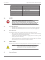
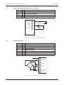
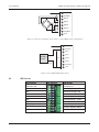
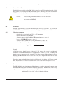
1
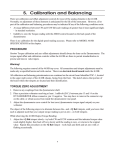
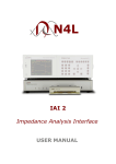
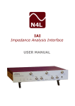
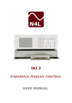
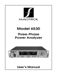
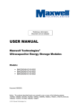
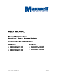
Model LMU 209 Load Monitoring Unit
1.0
Introduction
Figure 1 LMU 209 Load Monitoring Unit
1.1
Description
The LMU 209 Load Monitoring Unit is a high-precision, ultra stable DC-measuring amplifier that
is capable of various low-level mV-signals. The LMU 209 offers two calibrated outputs, a voltage
output and a current output, both according to the industrial standard. Coarse-gain and offset-range
are selected with easily accessible DIP-Switches. Fine tuning can be accomplished by adjusting
the 10-turn potentiometers. An additional low-pass filter reduces bandwidth and helps to improve
signal/noise ratio. The bridge power supply can be selected between 5 V or 10 V DC. The current
output is configured from 0–20 mA or 4–20 mA without any calibration.
1.2
Technical Specifications
Supply
Ripple Voltage
Voltage Output
Current Output
Operating Temperature Range
Housing Dimensions
18–28 V / 70 mA
max. 1 Vpp / 50 Hz
0 to ±10 V @ Rload 3 kΩ
0/4–20 mA @ Rload 0–800 Ω
-20 to +60 °C
44 × 74 × 51.4 mm
Housing Material
Protection Class
Weight
EMC Tests
Frequency Response
F.R. with selectable low-pass filter
Sensitivity (default)
Sensitivity Ranges
PA, Ul94 V-0 polycarbonate - aluminum (option)
IP 52 (polycarbonate) or IP 65 (aluminum)
100 g
EN 61000-4
0–500 Hz (-3 dB)
0–3 kHz ( -3 dB)
1 mV/V
Range 1 : 0.5 to 1.5 mV/V
Range 2 : 1.5 to 4.0 mV/V
1
User’s Manual
Magtrol Model LMU 209 Load Monitoring Unit
Adjustment Sensitivity
Zero Adjustment Ranges
Zero Fine Adjustment
Bridge power supply
Input-resistance Sensor
10-turn potentiometer
-75% to +75%, in 5 ranges
10-turn potentiometer
5/10 V DC (selectable)
5V: 120 Ω to 10 kΩ
10V: 330 Ω to 10 kΩ
100% (10 V or 20 mA), ± 0.8%
max. 20 mVpp
0.05 %
< 0.01% / °C
Calibration Signal
Noise
Linearity Error
TC Zero
2.0
Safety
Use caution and read this operating manual
thoroughly before beginning your installation
process. Setup, configuration and operation of the LMU
209 should only be conducted by qualified personnel.
2.1.
Proper Use of Equipment
• The LMU 209 Load Monitoring Unit must not be used in life-supporting applications.
• The LMU 209 Load Monitoring Unit must not be used in safety-critical applications.
2.2
Safety Precautions
Non-compliance with the safety regulations could result in serious damage to the unit.
• Always separate the signal lines from power lines (drives, converters) and never interrupt
the signal lines unless using designated junction boxes.
• Attach the cable shield (braid) at both ends to a proper ground. Do not allow a ground
current to flow over the cable shield.
• Attach all machine parts to one well defined potential by using large copper wires. Allowing
different potentials will create currents that cannot be controlled.
3.0
Installation
For quick and easy installation, select the operating mode as shown in “default position” section 3.2.1.
Caution:
Make sure the switches are in their correct end position. If
in doubt, toggle the switch again with the appropriate tool. Configuration can be done in the powered operate mode.
3.1
Connection Diagrams
2
User’s Manual
Magtrol Model LMU 209 Load Monitoring Unit
3.1.1
Supply Connection and Signal Output Connection
+Ub
0V
Uout
Iout
0V
1
2
3
4
5
Power supply, 18–28 V
Power supply 0 V (Ground)
Calibrated voltage output
Calibrated current output
Signal 0 V for UOUT and IOUT
0V PWR
+
I
0V Signal
U
I Out
+
3 4 5
U Out
+
1 2
+24VDC
Figure 2 Connection to Power and Control Unit
3.1.2
Sensor Connection
+15V
E+
Sen+
S+
SSenEEarth
16
15
14
13
12
11
10
9
Auxiliary supply output for external sensors (draw max. 20 mA)
Positive bridge excitation (5 V/10 V)
Sense input + (6-wire technique)
Positive signal input
Negative signal input
Sense input – (6-wire technique)
Negative bridge excitation 0 V
Connection for grounding
9 10 11 12 13 14 15 16
HFE
Excitation-
Signal-
Signal+
Excitation+
+15V
Figure 3 Connection of Resistive 4-wire Sensor
3
User’s Manual
Magtrol Model LMU 209 Load Monitoring Unit
9 10 11 12 13 14 15 16
HFE
Excitation-
SenseSignal-
Signal+
Sense+
Excitation+
+15V
Figure 4 Connection of Resistive 6-wire Sensor (contact Magtrol SA for information)
max. 20 mA
10 11 12 13 14 15 16
15 V
9
Auxiliary
Load
HFE
Excitation-
SenseSignal-
Signal+
Sense+
Excitation+
+15V
Figure 5 Use of LMU 209 Auxiliary Power
3.2
DIP Switches
OFF Position
DIP Switches
ON Position
Excitation 10V
N/A
Excitation 5 V
Sensitivity Range 1 ON
N/A
Sensitivity Range 2 ON
N/A-
Offset Range -50% (±20%)
N/A-
Offset Range -25% (±20%)
N/A-
Offset Range -0% (±20%)
N/A-
Offset Range +25% (±20%)
N/A-
Offset Range +50% (±20%)
Cut-Off Frequency 3 kHz
Cut-off Frequency 500 Hz
Zero Current Out 0 mA
Zero Current Out 4 mA
4
User’s Manual
Magtrol Model LMU 209 Load Monitoring Unit
3.2.1
Default Position
SW 1
SW 2
SW 3
SW 4
SW 5
SW 6
SW 7
SW 8
SW 9
SW 10
4.0
ON
ON
OFF
OFF
OFF
ON
OFF
OFF
ON
ON
5V Excitation
Range 1 selected
Offset adjusting range 0% ±20%
Bandwidth is limited DC–500 Hz
Current Out 4–20 mA
Operation
The LMU 209 is designed to amplify low-level signals from force, pressure or strain-sensors based
on strain gauge principles.
After supplying the LMU 209 with power, it is immediately ready for measuring and will deliver
a measuring signal at the signal outputs which is in perfect proportion to the input signal, coming
from the connected sensor. Depending on the sensor’s offset, it may be necessary to adjust the
potentiometer ZERO.
4.1
Offset calibration
The LMU 209 is optimized for static-measurement, as in force measuring and weighing applications.
If an exact proportional signal without any offset or zero-errors is desired, the zero of the whole
measuring chain has to be adjusted after installation. If the zero error is within a few percent, this
error can be adjusted by using the zero potentiometer. However, if the zero-offset is larger, the DIPswitches can be used to adjust the range. The DIP-switches can also be used to adjust for preload
or packaging weights.
ZERO potentiometer
10V potentiometer
Calibrate button
Figure 6 DIP-switches and Zero Potentiometer
5
User’s Manual
4.2
Magtrol Model LMU 209 Load Monitoring Unit
Adjusting Input Sensitivity
The default input sensitivity of the LMU 209 is adjusted to 1mV/V in conjunction with a bridge
supply power of 5 V. To adapt the LMU 209 to other signals, other ranges are easily selectable with
the DIP-switch or by adjusting the calibration with the potentiometer in large ranges.
Caution:
Adjusting the calibration will result in a loss of factory
calibration. Therefore only qualified personnel should
recalibrate the LMU 209.
4.3
Calibration
The LMU 209 contains a calibration button for quick and easy calibration. By pressing the
CALIBRATE button, the LMU 209 creates an internal signal of 1mV/V to the input.
4.3.1
Calibration procedure
1. Calculate the sensor signal in mV/V for a 10V output span.
2. Connect the sensor to the LMU 209.
3. Adjust the output to 0.00 V with the ZERO potentiometer (see Figure 6)
4. Press the CALIBRATE button (see Figure 6)
5. Adjust the voltage-output with the 10V potentiometer (see Figure 6),
according to the following formula:
UOUT (Volt) =
10V × 1 (mV/V)
Sensor signal (mV/V)
Example:
A 5 kN force-sensor should measure a force of 3.5 kN, whereas this sensor is specified with
2.00  mV/V at 5kN. Therefore, the sensor’s output will be 1.40 mV/V at 3.5 kN. According to the
formula above, the output needs to be adjusted to 7.143 volts when the calibration button is pressed.
After this, the LMU 209 will deliver 10.00 V (or 20 mA) at the outputs when the sensor is loaded
with 3.5 kN.
The voltage output can handle bipolar signals and will therefore also deliver -10 V. In the example
above, negative forces can also be measured as long as the sensor itself is designed to do so.
4.4
Current output
The LMU 209 offers two simultaneous calibrated outputs, a voltage output and a current output.
The relationship between these two outputs is strictly proportional. In other words, if the voltage
output is forced to 100%, the current output will also go to 100%.
Definition: UOUT 0 to +10 V = IOUT 0–20 mA or 4–20 mA
6
User’s Manual
Magtrol Model LMU 209 Load Monitoring Unit
4.5
Grounding (HFE)
The LMU 209 provides outstanding EMC capabilities but still needs to be connected to an earthground. This connection should be made with a short wire with at least AWG22. If an earth-ground
is not possible, attach this connection to 0 V or a mounting plate or case. Make sure that the HFE
is connected to a proper earth-ground to sink the energy which is absorbed by the EMC circuit
integrated in the LMU 209.
4.6
Power
Bridge power can be selected between 5 V DC or 10 V DC. As a general rule, low impedance sensors
should be driven with 5V whereas high impedance sensors can be operated with 10V. If in doubt,
select the lower supply voltage. This helps to reduce sensor overheating.
4.7
6-wire Technique
Contact Magtrol SA for additional information
4.8
Low-Pass Filter
The onboard low-pass filter is switched on and off by toggling the appropriate DIP Switch. It is
recommended to reduce the bandwidth, because it eliminates high-frequency noise and gives more
stability to the readings. If an application needs more speed, switch off the low-pass filter in order
to achieve a bandwidth up to 3000 Hz.
5.0
Maintenance
Any repairs should be performed exclusively by Magtrol.
1st Edition – January 2009
Testing, Measurement and Control of Torque-Speed-Power • Load-Force-Weight • Tension • Displacement
Magtrol Inc
70 Gardenville Parkway
Buffalo, New York 14224 USA
Phone: +1 716 668 5555
Fax: +1 716 668 8705
E-mail: [email protected]
Magtrol SA
Route de Montena 77
1728 Rossens / Fribourg, Switzerland
Phone: +41 (0)26 407 3000
Fax: +41 (0)26 407 3001
E-mail: [email protected]
7
www.magtrol.com
Subsidiaries in:
Germany • France
China • India
Worldwide Network
of Sales Agents