1
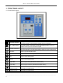
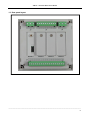
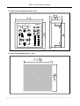
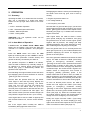
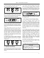
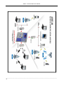
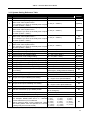
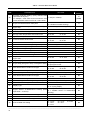
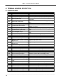
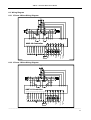
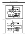
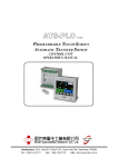
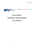
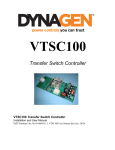
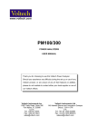
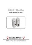
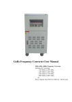
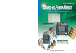
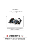
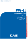
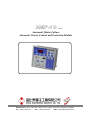
AMF-10
Ver1.0
Automatic Mains Failure
Automatic Genset Control and Protection Module
Headquarters : No.3, Lane 201, Chien Fu ST., Chyan Jenn Dist., Kaohsiung, TAIWAN
Tel : + 886-7-8121771
Fax : + 886-7-8121775
URL : http://www.kutai.com.tw
AMF-10
Automatic Mains Failure Module
TABLE OF CONTENTS
Section
Page
ATTENTION .............................................................................................................................................. 3
PROJECT BACKGROUND ...................................................................................................................... 3
INTRODUCTION ....................................................................................................................................... 3
AMF-10 MONITORING AND PROTECTION FUNCTION ........................................................................ 3
1. FRONT PANEL LAYOUT ..................................................................................................................... 4
1.1 Front Panel Layout........................................................................................................................... 4
1.2 Rear panel layout ............................................................................................................................. 5
1.3 Unit Dimensions (Measurement:mm)............................................................................................ 6
1.4 Panel Cut-out (Measurement:mm) ................................................................................................ 6
2. OPERATION ......................................................................................................................................... 7
2.1 Summary.......................................................................................................................................... 7
2.2 Auto Mode Of Operation .................................................................................................................. 7
2.3 Off Mode Of Operation..................................................................................................................... 8
2.4 Manual Mode Of Operation.............................................................................................................. 8
2.5 Test Mode Of Operation................................................................................................................... 8
3. SYSTEM SETTING & OPERATION ..................................................................................................... 8
3.1 DC Input ........................................................................................................................................... 8
3.2 System Setting ................................................................................................................................. 8
3.3 Operation Timer Setting ................................................................................................................... 9
3.4 AC Voltage & Current Display Setting ............................................................................................. 9
3.5 Engine Over-Load Protection Setting .............................................................................................. 9
3.6 User Specified Monitoring Setting Alarm1 & Alarm2 ..................................................................... 10
3.7 Service & Maintenance Setting ...................................................................................................... 10
3.8 Panel Display Setting ..................................................................................................................... 10
3.9 Engine Idle Operating Function ..................................................................................................... 10
3.10 Automatic Transferring Switch (ATS) Function............................................................................ 11
3.11 Communication With PC (KCU-XX)............................................................................................. 11
3.12 Lamp Testing ............................................................................................................................... 11
3.13 System Setting Reference Table ................................................................................................. 13
4. SYSTEM WARNING FAILURE DESCRIPTION ................................................................................. 15
4.1 Failure Signal Reference Table ..................................................................................................... 15
4.2 Warning Mode................................................................................................................................ 15
4.3 Shutdown Mode ............................................................................................................................. 15
5. SPECIFICATION ................................................................................................................................. 15
6. TERMINAL & WIRING DESCRIPTION .............................................................................................. 16
6.1 Connection Detail........................................................................................................................... 16
6.2 Wiring Diagram .............................................................................................................................. 17
______________________________________________________________________________________
2
AMF-10
Automatic Mains Failure Module
ATTENTION
● Engine running hours meter
This document is intended to cover the installation,
operation and maintenance of the AMF-10
automatic genset control and protection module. It is
a guide for qualified personnel.
● DC battery voltage
Carefully read this manual before installation.
PROJECT BACKGROUND
Automatic Transfer Switches protect electrical
equipment against power loss. The normal power
source (power grid) is backed up by a standby
(emergency generator). The transfer switch is
connected to both and is made to supply the load
from either one. In the event power is lost from the
normal source, the generator is started and the
transfer switch transfers to standby power. Once
normal power is restored, the ATS transferred back
to the grid and waits for the next electrical failure.
The AMF-10 module constantly checks the power
coming from the grid for problems related to over /
under voltage or a missing phase.
INTRODUCTION
The AMF-10 is one control with two jobs, one is to
protect and control the emergency generator and
the other is to monitor and control the Automatic
Transfer Switch.
The customer can program the AMF-10 module
directly from the front panel without using a
computer. Any new settings are recorded into the
internal (EEPROM) and protected from erasure
even without battery.
● Also the display shows all time delays and
countdown function as they occur
● It also displays the program setting parameters
as you change or reprogram the module
You can also change the way the display works, it
can either be fixed ; changing from one value to the
other by pushing a button or displaying each line for
2 sec. in succession.
In conclusion the AMF-10 offer all the necessary
protection and monitoring needed for any standby
power genset.
AMF-10 MONITORING AND PROTECTION
FUNCTIONS
● Normal power full phase over / under voltage
monitoring and lost of phase
● Standby power full phase over / under voltage
monitoring and lost of phase
● Standby power full phase load current monitoring
● Engine high water temperature protection
● Engine low oil pressure protection
● Engine over/under speed protection
● Engine start failure warning
● External emergency stop warning
● Battery over and under voltage monitoring
● Low fuel level monitoring
AMF-10 has 2 extra inputs for the customer to use
and set-up, like fuel overflow, radiator water levels,
etc.
The AMF-10 has 4 settings; Automatic (AUTO) Manual (MANU) - Testing (TEST) and Shutdown
(OFF) in addition to this four buttons the front panel
has a 4 digital, 7 segment numerical displays
showing all the alternating Volts, Amps and Hertz,
Battery Volts and engine running Hours readings
and the programming interface for changing all the
engine, ATS and generator parameters.
The 4 Digital displays shows :
● Normal and emergency AC voltage
● Normal and emergency load current
● Normal and emergency AC frequency in Hertz
______________________________________________________________________________________
3
AMF-10
Automatic Mains Failure Module
1. FRONT PANEL LAYOUT
1.1 Front Panel Layout
ICON
DESCRIPTION
Decrease / Selection
SET / Failure Reset
Increase / Selection
ATTENTION
IN Program mode, press to decrease value
In normal operation, press to display voltage, current or frequency
IN OFF mode, press and hold button for 4 seconds to enter Program mode
IN normal operation, press button to select and display phase L12, L23, L31
IN failure status, press to erase alarm signal
IN Program mode, press to increase value
IN normal operation, press to display battery voltage or engine running hours
Automatic
Press to go into Automatic mode
Stop
Press to enter Shutdown / System Off mode
Test
Press to enter Testing mode
Manual
Press to go on Manual mode
Engine Start
Manual engine start (ON MANUAL MODE ONLY)
Engine Stop
Manual engine shutdown (ON MANUAL MODE ONLY)
Normal Power
Connect to Load
Manual Transfer the Switch from Emergency to Normal Position
(ON MANUAL MODE ONLY)
Emergency Power
Connect to Load
Manual Transfer the Switch from Normal to Emergency Position
(ON MANUAL MODE ONLY)
______________________________________________________________________________________
4
AMF-10
Automatic Mains Failure Module
1.2 Rear panel layout
______________________________________________________________________________________
5
AMF-10
Automatic Mains Failure Module
1.3 Unit Dimensions (Measurement:
:mm)
L 12
Volt
L 23
AMF-10
L 31
Batt
Amp
Freq
Hour
1.4 Panel Cut-out (Measurement:
:mm)
______________________________________________________________________________________
6
AMF-10
Automatic Mains Failure Module
2. OPERATION
2.1 Summary
Disengaging the starter is vital to prevent damage to
the starter motor and ring gear, and is done by
sensing.
Operating the AMF-10, is divided into four functions;
each one is controlled by a single push button
located on the top right hand corner of the front
panel.
● Engine Oil pressure switch on
1. AUTO : Automatic Operation
Next the AMF-10 goes into idle (only if you have the
proper engine governor idle connection), the screen
shows 【Id.XX】. Each entered value equals to 5sec
idle delay (see page 12). To disable enter 0 and the
engine will not idle.
2. OFF : Shutdown/System OFF Mode
3. MANU : Manual Operation
4. TEST : Testing Mode
(CAUTION) only one operation mode can be
selected at one time.
2.2 In Auto Mode of Operation
In AUTO mode, the START - STOP - MAIN - GEN
buttons do not operate. They work only when the
controller is in Manual operation. See paragraph
2.5.
Press the AUTO button and notice the LED
lights-up confirming that you are in AUTO. In AUTO
mode the ATS (Automatic Transfer Switch) and
genset are directly controlled by the AMF-10.
The operation sequence in AUTO is as follows;
when the AMF-10 detects any unusually voltage or
no voltages or a missing phase coming from the
normal (city grid), it automatically initiates the
generator start sequences.
First activating the engine Preheat, and at the same
time displaying the Pre-Heat countdown in seconds
【PH.XX】on the front screen.
Second, after the preheat times out, the starter
motor begin to start and the screen displays the
starter motor running time【St.XX】 The starter
motor runs for 6 sec. (the user can change the
running time of the starter motor for up to 30
seconds) If the engine fails to start the first time, the
AMF-10 returns to Preheat and tries again. The
AMF-10 tries 3 times (The user can also change how
many times the engine tries to start - up to 9 times).
If the engine fails to start, the AMF-10 lights-up the
LED for Start Failure icon, and the screen flashes,
FAIL.
● AC voltage builds up
● AC frequency over 18Hz
After engine starts, the AMF-10 enters a 30sec
grace period, delaying any shutdowns, and giving
the generator time to reach normal engine speed,
together with oil pressure, AC voltage and other
operating parameter, the screen displays【Ac.XX】
after confirming that everything is running OK.
But if the genset does not run normally before the
30sec grace period is up, the module shutdown the
generator displaying the reason for stopping the
genset on the front panel.
Now if the generator stabilizes and reaches its rated
output, The AMF-10 starts the TDNE (Time Delay
Normal to Emergency) countdown, showing
【nE.XX】on the front screen. (Remember that each
entered value is equals to 5sec delay, the preset
TDNE countdown is 10sec, See page 12). When the
countdown stops, the module sends a signal to the
transfer switch to change-over from normal to
emergency (standby generator) power. If the
transfer switch fails to do this in 15sec, the AMF-10
flashes emergency on LED and display FAIL on the
screen, after the problem is resolved, press the SET
/ Failure reset button to remove the warning signal.
As soon as Normal power returns, the AMF-10
verifies this and begins the TDEN (Time Delay
Normal to Emergency) countdown showing
【En.XX】on the screen. Again each entered value
equals 5sec, the factory preset TDEN countdown is
10sec (see page 12). When the countdown stops,
the module sends a signal to the transfer switch to
change-over from emergency to normal power.
Finally the engine executes TDEC. (Time Delay
Engine Cool down) The screen display【CL.XX】
Again each entered value equals to 5sec; the preset
TDEC count down is 60sec (See page 12).
But if the engine starts normally the AMF-10
immediately disengages the starter motor.
______________________________________________________________________________________
7
AMF-10
Automatic Mains Failure Module
ATTENTION
When the generator is on Engine Cool-down
the AMF-10 protection system remains in
effect and if any failure occurs, the module
bypasses the countdown and shutdown
generator immediately.
After Engine Cool down, the AMF-10 cuts the
Engine fuel by using either one of two different
methods (either Energize to Stop or Energize to
Start), the AMF-10 display【SP.XX】on the front
screen.
In AUTO mode, AMF-10 allows the operator to use
a remote signal to test the generator With or Without
LOAD (programmable). Under no load testing, the
AMF-10 starts the genset, but do not test the
transfer switch and the generator remains without
load. If conducting the test with load, the module
starts the genset and using the transfer switch puts
the generator on load.
2.3 Off Mode of Operation
OFF mode not only serve as shut down of the
genset, but also serve as Failure Reset. Under OFF
mode, all output functions are disable; this includes
the control signal for the transfer (changeover)
switch. When switching to 【OFF】 position during
the normal genset operation, the module shutdown
the genset according to normal shutdown sequence.
If AMF-10 detects a major malfunction during a
normal operation, it executes the Emergency
Shutdown immediately to prevent further damage to
the genset. Once the generator completely stops,
the reason for the failure is displayed on the front
panel, helping maintenance locate the problem. To
erase the failure signal, press the【SET / FAILURE
Reset】key or switch to OFF position.
On OFF mode, the operator can press the Increase
/ Selection【︽】button, to get other readings for
battery voltage and Operating hours. This readings
are switched from one to the other every 2sec.
2.4 Manual Mode of Operation
【START】Manual Engine Start
【STOP】Manual Engine Stop
【MAIN】Manually change over to Normal Power
【GEN】Manually change over to (Stand by) Power
The Engine Start, Shutdown and transfer switch
changeover sequence under MANU mode is the
same as the AUTO mode, reference from Section
2.2 (page 7).
2.5 Test Mode of Operation
TEST mode is testing function operated under no
load from the genset. When switching AMF-10 into
TEST mode, if the system with load and under
normal power supply status, the module only start
up the genset to conduct a test with no load and
dismiss the test for the transfer switch changeover.
If the normal power failure occurs during operation
of TEST mode, The AMF-10 overwrites the testing
operation and automatically carryout the transfer
switch changeover to the emergency power on.
When the normal power returns, the module
continue to supply power from the emergency
power supply until the module is switched back to
AUTO mode.
3. SYSTEM SETTING & OPERATION
ATTENTION
Before changing factory setting on the AMF-10,
make sure all connections are correctly made,
(connect the battery last). If you are
programming new values to the AMF-10, refer
to front panel layout (page 4) and the system
programming table on page 13.
3.1 DC Input Supply
The AMF-10 is capable of working with a wide range
of input voltages (9VDC to 36VDC) this helps
prevent damage to the control from low battery
voltage when the engine is cranking.
3.2 System Setting (programming)
Changing the settings for the AMF-10 consists of
scrolling down throw 53 lines of programming and
one by one changing each line to the requirement
needs for your generator. The operator can input
and change the settings by using the buttons on the
front panel.
On MANUAL, the operator can manually start and
stop the generator and activate the transfer switch
to go from Normal to Emergency solely by using the
START – STOP – MAINS – GENERATOR buttons
on front of the AMF-10.
______________________________________________________________________________________
8
AMF-10
Automatic Mains Failure Module
To enter new setting, select OFF, and then hold
SET / Failure Reset button down for 4sec.
If you need to reset the operating hours, follow
section 3.2 Enter the System Setting. And before
the 【Pro.】message disappears (you have 4sec),
press down【OFF】button for 4sec, when the screen
shows【Ch.Hr】 (see the following diagram), this
means the AMF-10 is in the operating timer setting.
Batt
Volt
The first thing the screen shows is 【Vr1.0】 for 2sec,
(this is the software version number) after that it
changes to【Pro.】for Programming, next the display
changes to looks like the frame underneath.
Volt
Batt
Amp
Freq
Hour
Now you can change the hour-meter by using the
UP / DOWN arrows.
3.4 AC Voltage & Current Display Setting
Amp
Freq
Hour
The first 2 digits represent the line number from 01
to 53, the last 2 digits stand the values for that line.
You can change the value of the last 2 digits by
using the UP and DOWN arrows following the table
on (3.11)
Under System Setting, each time you press the
【Setting】button, the next line comes up with a
complete new set of values. (See Table on page 12),
One by one input the settings until all new setting
are written. When you reach the last line the panel
will say 【 End 】 this means the setting are
completed and memorized by the internal micro
processor. You can also END at any time by holding
the Setting button for 4sec.
To reset the factory setting you need to hold down
the 【Down】【SET】【UP】buttons(See below
diagram)together for 4sec until “ Au.PO ” appears
on the screen.
The AMF-10 continually monitors normal and
generator power displaying these values on the
front panel. The AMF-10 monitors full phase voltage,
current and frequency (The voltage and current
value is calibrated and adjusted at the factory). But if
the load has high capacitive or inductive values the
waveform distortion may cause the displayed to
have small differences from the users measuring
instrument.
You can adjust the display value to equal to the
users own instruments, by entering the voltage
setting mode to perform adjustment and increase or
decrease the parameter. Once the adjustment is
completed, the 3 phase sensing value increase or
decrease according to the adjusted value and
display it on the display screen. The AMF-10 over
voltage, under voltage and the load current
protection follow the adjusted value as the actual
system voltage and perform the monitoring
according to the new parameter.
See System entry Setting Reference Table lines (6),
(7), (11), (12), (23), (24) for all AC voltage, current
display parameter and settings.
3.5 Engine Over-Load Protection Setting
ATTENTION
3.3 Operation Timer Setting
The running hour meter total is stored in the internal
memory and cannot be erased or return to zero by
ether removing the battery or by resetting to factory
settings.
AMF-10 provides overload protection from
the generator only. There is no overload
protection on the normal side.
______________________________________________________________________________________
9
AMF-10
Automatic Mains Failure Module
To prevent overloading the genset the AMF-10 has
an overload protection inputs. It is set according to
the generator maximum current output, or any
current value below its rated output.
Set the overload protection via the System Setting
Lines 26 to 28. Each value equals to 50 ampere.
For example: When the number set is 20, the over
current value is equals to 20 * 50A = 1000A.
When an engine overload is detected, the AMF-10
overload make sure timer starts and if the
over-current condition disappears within the grace
period set, the system ignores the incident and
resets, but if the overload condition exceeds the
preset grace period, the AMF-10 execute the
overload protection and display the overload failure
message on the screen, in at the same time perform
corresponding overload trip output signal.
3.6 User Specified Monitoring Setting
Alarm1 & Alarm2
The AMF-10 has 2 spare inputs to add two more
protections to the system.
See Line entry (44), (45), (46), (47), (48), (49), The
two inputs can be setup as a Warning or a shutdown.
3.7 Service & Maintenance Setting
The AMF-10 includes a maintenance indicator.
When the engine reaches a service interval, the
panel displays (Service) advising the staff to carry
out scheduled maintenance. When programming
service setting, remember that each value
represents 10hrs of operating time, for example:
when setting value is 20, the timer setting equals to
20 *10Hr = 200Hr.
system
Once maintenance is finished, go to line (53) to
reset the service timer back to (0).
● Overload Shutdown : When engine overloads,
the module immediately stop the engine
operation, display failure signal on the panel and
in the same time perform corresponding overload
trip output signal.
Refer to System Setting Table line (52), (53) for
Service and maintenance setting and related
information.
● Overload Warning : When engine overloads, the
module does not stop the engine, it only display a
warning failure signal on the panel, in the same
time perform corresponding overload trip output
signal. This signal can be used to trip a breaker
to make the generator to cool down under no
load.
The AMF-10 display can be set to fix or cycling. Line
(51) In cycling the AMF-10 take turns displaying in
sequence Volts, Amps, Hz on the screen for 2sec.
To read Operating hours and Battery Voltage you
must override the display by using the increase【︽】
the 【SET】button to select readings of L12、L23 and
L31 phase, and decrease【︽】button to see battery
voltage and operating hour.
AMF-10 provides both warning
shutdown for overload protection.
and
See System Entry Setting Reference Table lines
(25), (26), (27), (28) for all overloads protection
parameter and settings.
ATTENTION
When using the AMF-10 for overload
protection, you need to pay special attention
not to exceed the CT primary rated current,
otherwise the CT will saturation cause
incorrect readings leading to a failure in
overload protection.
For example:
:CT ratio equals to 1000A:
:5A,
then over current setting value can not
exceed 1000A.
3.8 Digital Display Setting
When a specific parameter is selected, the cycling
display pauses and display the selected parameter
for 30sec, after 30sec the system resumes the
cycling parameter display.
See System Setting Reference Table entry line (51)
for display type setting and related information.
3.9 Engine Idle
To prevent operating the engine at full speed
immediately after starting and give it time to heat up,
the AMF-10 can operate the engine in idle mode,
allowing the genset to warm up. The operator can
define the time on idle according to onsite and
climate requirements.
______________________________________________________________________________________
10
AMF-10
Automatic Mains Failure Module
Go to the System Setting Reference Table line (05)
for Engine idle operation function setting and related
information.
This is only possible if the Genset has an electrical
governor control.
3.10 Automatic Transferring Switch (ATS)
Function
When the AMF-10 is in AUTO, the module monitors
street power. If any voltage abnormity or open
phase is detected, the module sends a start signal
to the genset in order to start the engine and provide
continual power supply to the load.
AMF-10 has 2 electrical interlock control signals
TDNE (Time Delay Normal to Emergency) and
TDEN (Time Delay Emergency to Normal), The
system control sequence fist disconnect with time
delay then engage, to ensure Transfer Switch not
engage normal power supply and emergency power
supply at the same time.
Go to the System Setting Reference Table line (02),
(03), for ATS (Automatic Transfer Switch) for setting
information.
Free App developed by Kutai Electronics to enables
user to remotely monitor and operate ATS or
generator via portable mobile device. Software
currently available with Apple iOS5.1 and Android
Ver.2.3.3 system and above. Other operating
system software will be available at a later time.
Free software can be downloaded from App Store or
Google Play by simply key in “Kutai” and hit search.
KCU-01 – USB interface module.
KCU-02 – RS-485 interface module.
KCU-03 – Ethernet interface module.
For remote communication settings please refer to
system setting reference table entries (54), (55),
(56).
When the item (54) set to 00, then user can read all
the real time information from the controller only. But
when it set to 01, it allow remote control from PC
also.
The items (55), (56) is for KCU-02 RS485 interface
module used only, others don’t care.
For detail information please refer to the KCU-XX
user manual.
3.11 Communication With PC (KCU-XX)
AMF-10 with optional USB / RS485 / Ethernet
remote communication functions. User can easy
read all the real time information and remote control
the local device via communication interface
modules. There are 3 different purpose interface
modules show as below :
NOTE
When use the KCU-02 to make a closed LAN,
Different controller address setting must be
different and the Baud rate setting must be
the same.
3.12 Lamp Testing
WARNING
The AMF-10 can be remotely controlled and
genset may start up at anytime. Place a
visible warning sign next to or on the
generator, stating “Danger! The generator
may start up at anytime!” and installing a
warning buzzer or flash warning light is
highly
recommended.
Unwarned
or
unscheduled remote operation may result in
serious injury or even death. When
performing service or maintenance, always
disconnect remote signal input.
The AMF-10 controller provided lamp test function
for user to check all the LEDs and displays on the
front panel.
To run lamp test, set the controller in OFF mode first.
Press the OFF button then all the LEDs and
displays will be illuminated immediately. When the
OFF button released the controller will return to
normal operation.
______________________________________________________________________________________
11
AMF-10
Automatic Mains Failure Module
______________________________________________________________________________________
12
AMF-10
Automatic Mains Failure Module
3.13 System Setting Reference Table
ITEM
DESCRIPTION
1
Phase selection (3Ø3W 1Ø3W or 1Ø)
TDEN Time Delay Emergency to Normal
Each enter value equals to 5sec
For example If you enter 5, the delay time is equal
to 25sec (5*5sec = 25sec)
TDNE Time Delay Normal to Emergency
Each enter value equals to 5sec
For example if you enter 5, the delay time is equal
to 25sec (5*5sec = 25sec)
TDEC Time Delay Engine Cooling
Each enter value equals to 5sec
For example if you enter 5, the delay time is equal
to 25sec (5*5sec = 25sec)
Engine idle time delay setting
Each enter value equals to 5sec
For example if you enter 5, the delay time is equal
to 25sec (5*5sec = 25sec)
Normal power voltage display function setting
Normal power voltage display adjustment setting
Normal power over voltage setting
Normal power under voltage setting
Normal power voltage abnormity validating time setting
Emergency power voltage display function setting
Emergency power voltage display adjustment setting
Emergency power over voltage setting
Emergency power under voltage setting
2
3
4
5
6
7
8
9
10
11
12
13
14
15
16
17
18
19
20
21
22
23
24
25
FACTORY
SETTING
SETTING
00
3Ø3W
01
1Ø3W 02
1Ø
00
0 ~ 60 ( 0 ~ 300sec )
2 (10sec)
0 ~ 60 ( 0 ~ 300sec )
2 (10sec)
0 ~ 60 ( 0 ~ 300sec )
12
(60sec)
0 ~ 60 ( 0 ~ 300sec )
00
00
Tune Up
01
Tune Down
00~ 99 V
11 ~ 50 ( 110V ~500V )
08 ~ 47 ( 80V ~ 470V )
2 ~ 99sec
00
Tune Up
01
Tune Down
00~ 99 V
11 ~ 50 ( 110V ~500V )
08 ~ 47 ( 80V ~ 470V )
Emergency power voltage abnormity validating 0 ~ 99sec
time setting
(0 Emergency Voltage detection disabled)
Emergency power voltage abnormity execution
00
Warning
01
Engine stop
Engine over speed set point
51 ~ 75HZ
00 ~ 99 sec
Engine over speed validating time setting
(0 − Engine Over Speed disabled)
Engine under speed set point
40 ~59HZ
00 ~ 99 sec
Engine under speed validating time setting
(0 − Engine Under Speed disabled)
Engine under speed execution
00
Warning
01
Engine Stop
00
Load
01
Normal
Current Transformer (CT) installed position
02
Emergency
AC current display function setting
00
Tune Up
01
Tune Down
AC current display adjustment setting
00~ 99 A
1 ( 25/5)
2 ( 50/5)
3 ( 60/5)
Rated Current Transformer (CT) ampere setting
5 ( 100/5)
6 ( 150/5)
For example: default value set to 5 = 100A/5A 4 ( 75/5)
7 ( 200/5)
8 ( 250/5)
9 ( 300/5)
current transformer (CT) is selected
10 ( 400/5)
11 ( 500/5)
12 ( 600/5)
(When external rated current transformer rating 13 ( 750/5)
14 ( 800/5)
15 ( 1000/5)
and setting differs from the specified, the current 16 ( 1200/5)
17 ( 1500/5)
18 ( 1600/5)
readings may become inaccurate)
19 ( 2000/5)
20 ( 3000/5)
00
00
25 (250V)
18 (180V)
10sec
00
00
25 (250V)
18 (180V)
10
01
65HZ
05
55HZ
05
01
00
00
00 A
05
______________________________________________________________________________________
13
AMF-10
ITEM
26
27
28
29
30
31
32
33
34
35
36
37
38
39
40
41
42
43
44
45
46
47
48
49
50
51
52
53
54
55
56
Automatic Mains Failure Module
DESCRIPTION
FACTORY
SETTING
SETTING
Overload protection setting. (every defined value
represents 50 ampere)
2
1 ~ 60 (50 ~ 3000A)
(100A)
For example : enter value 20, this means the over
current activation value is set to 20 * 50A=1000A
00 ~ 99sec
0
Engine overload activation delay time
(0 = Disable overload warning)
Set engine overload protection as warning or
00
00
Warning
01
Engine stop
engine stop
01
Oil pressure switch as NO or NC
00
NO
01
NC
05
Low oil pressure warning confirmation time
02 ~ 99 sec
00
Set high water temperature switch NO or NC
00
NO
01
NC
05
High water temperature activation delay time
02 ~ 99 sec
00 ( No fuel level switch)
00
Fuel level switch as NO or NC
01
NO
02
NC
10
Low fuel level activation delay time
02 ~ 99 sec
00
Set low fuel level as Warning or Engine stop
00
Warning
01
Engine stop
08 VDC
Battery under voltage setting
08 ~ 23 VDC
32 VDC
Battery over voltage setting
13 ~ 35 VDC
06
Engine preheat time setting
00 ~ 99 sec
03
Attempts permitted to restart engine
01 ~ 09
06
Starter motor crank time setting
02 ~ 30 sec
Oil pressure switch selected to check and permit
01
00
NO
01
YES
engine start
10
Engine Stop Time Setting
02 ~ 99 sec
00 (Energize to stop
00
Engine Stop (Energize to stop or energize to start)
01 (Energize to start
00
No Alarm1 input signal
00
User defined Alarm1 as NO or NC type
01
NO
02
NC
10
Set Alarm1 time configuration
02 ~ 99 sec
00
Set Alarm1 signal as Warning or Engine stop
00
Warning
01
Engine stop
00
No Alarm2 input signal
00
User defined Alarm2 as NO or NC type
01
NO
02
NC
10
Set Alarm2 time configuration
02 ~ 99 sec
00
Set Alarm2 signal as Warning or Engine stop
00
Warning
01
Engine stop
01
External remote testing with load or without load
00
With load 01
Without load
00
Fixed display
01
Display Type
01
Cycling display
00 ~ 25 (0 ~ 250Hours)
Engine Service & Maintenance warning (Each
00
(0 = Disable service & maintenance
input value = 10 hours)
warning)
01
Reset Service & Maintenance warning timer
00
YES
01
NO
00
Enable remote control by KCU-xx Module
00
NO
01
Yes
00
KCU-02 module address setting
00
None
01 ~ 99
KCU-02 Baud rate setting
01
04
07
09
115200
19200
4800
1200
02
05
08
57600
14400
2400
03
06
38400
9600
03
______________________________________________________________________________________
14
AMF-10
Automatic Mains Failure Module
4. SYSTEM WARNING & FAILURE
DESCRIPTION
4.1 Failure Symbol Reference Table
AMF-10 has a 7 segment display screen in addition
to individual LED graphic indicators showing the
operator of all operating status.
Icon Reference Table
WARNING
SIGNAL
4.2 Warning Mode
If the AMF-10 detects a fault and this fault is a minor
problem the AMF-10 gives you a warning. If the fault
is hazardous to the engine or generator, it shutdown
immediately depending how it has initially setup If it
is a warning the genset continue to work, but all the
warning signals remain illuminated on the front
panel and continue to be displayed until repaired.
4.3 Shutdown Mode
DESCRIPTION
EXECUTION
Engine Start Failure
Shutdown
Emergency
Shutdown Activated
Shutdown
High Water
Temperature
Shutdown
Low Oil Pressure
Shutdown
If the AMF-10 detects a mayor problem on the
generator the module executes an Emergency
Shutdown, showing the reason for the failure, and
guiding the maintenance staff to perform repairs,
and after all failures are fixed, switch to【OFF】OFF
mode or hold【SETTING / Failure Reset】 button
(key) to erase the failure signal, restart the genset
and load test and see if the problems are eliminated.
Over-speed
Shutdown
5. SPECIFICATION
Shutdown
or Warning
Shutdown
or Warning
Shutdown
or Warning
Shutdown
or Warning
Shutdown
or Warning
ITEM
SPECIFICATION
DC Supply
9 ~ 36 VDC
Alternator Input Range 15 ~ 510 VAC (Ph-Ph)
Alternator Input
50 ~ 60 Hz
Frequency
Start Signal Output
8 Amp @ 12/24VDC
Fuel Solenoid Signal
8 Amp @ 12/24VDC
Output
Preheat Signal Output 8 Amp @ 12/24VDC
Accessory “ON”
8 Amp @ 12/24VDC
Output
Idle Control Conductor
8 Amp @ 12/24VDC
Capacity
Warning Signal Output 8 Amp @ 12/24VDC
Overload Alarm Output 8 Amp @ 12/24VDC
Normal Power Connect
8 Amp @ 250VAC
to Load Signal
Stand by Power
Connect to Load
8 Amp @ 250VAC
Signal
Power Consumption
Under 5VA
Operating Temperature -20 to 70℃
Under-speed
AC over voltage
AC under voltage
Genset Over-load
Low Fuel Level
Low Battery Voltage
Warning
Service &
Maintenance
Warning
Spare Setting 1
Spare Setting 2
Normal Power
available
Warning
Warning
Shutdown
or Warning
Shutdown
or Warning
Relative Humidity
Under 95%
%
Rated CT Capacity
Above 2.5VA
Secondary Rated
current
Weight
5A
589 g ± 2%
______________________________________________________________________________________
15
AMF-10
Automatic Mains Failure Module
6. TERMINAL & WIRING DESCRIPTION
6.1 Connection Detail
PIN No.
DESCRIPTION
J1-1
Null
J1-2
Battery negative (-V)
J1-3
Battery positive (+V)
J1-4
J1-5
J1-6
J1-7
J1-8
J1-9
J1-10
J1-11
J1-12
J1-13
J1-14
J1-15
J1-16
J1-17
J1-18
J2-1
J2-2
J2-3
J3-1
J3-2
J3-3
J3-4
J3-5
J3-6
J3-7
J3-8
J3-9
J3-10
J4-1
J4-2
J4-3
ATTENTION
Spare
System DC negative input. (Battery Negative).
System DC positive input. (Battery Positive).
Used to control external alarm buzzer. Supply (+V) 8
Alarm signal Output
Amp rated
Connect to Governor Idle control. Supply (+V) 8 Amp
Idle control signal output
rated
Starter motor Signal Output
Connect to Starter Motor. Supply (+V) 8 Amp
Connect to Fuel Solenoid or Fuel Valve Control.
Fuel Solenoid Signal Output
Supply (+V) 8 Amp
Accessory “ON” Output
Connect to the panel lamp. Supply (+V) 8 Amp
Used to trip the AC output breaker. Supply (+V) 8
Overload alarm signal output
Amp
Used to control the internal Heater. Supply (+V) 8
Pre-heat Signal Output
Amp
Emergency Stop Signal Input
Connect to external emergency stop switch
Temperature Switch Input
Connect to Temperature Switch
Oil Pressure Switch Input
Connect to Oil Pressure Switch
Fuel Level Switch input
Connect to Fuel Level Switch
Spare1 / User Define Warning Negative input When Action
Signal Input
Spare2 / User Define Warning Negative input When Action
Signal Input
Remote Start Signal Input
Connect to external remote test switch
Null
spare
Normal L1 sensing input.
Connect to the Normal power phase L1
Normal L2 sensing input.
Connect to the Normal power phase L2
Normal L3 sensing input.
Connect to the Normal power phase L3
Normal “ON” signal output
Connect to normal “ON” Coil. Supply 8 Amp
Normal “ON” signal output
Connect to normal “ON” Coil. Supply 8 Amp
Emergency “ON” signal output
Connect to Emergency “ON” Coil. Supply 8 Amp
Emergency “ON” signal output
Connect to Emergency “ON” Coil. Supply 8 Amp
Normal “ON” feedback signal input Connect normal “ON” feedback switch
Emergency “ON” feedback signal Connect Emergency “ON” feedback switch
input
CT comm. terminal input
Connect to external CTs common position
CT secondary for L1
Connect to secondary of L1 monitoring CT
CT secondary for L2
Connect to secondary of L2 monitoring CT
CT secondary for L3
Connect to secondary of L3 monitoring CT
Emergency L1 sensing input.
Connect to the genset power phase L1
Emergency L2 sensing input.
Connect to the genset power phase L2
Emergency L3 sensing input.
Connect to the genset power phase L3
______________________________________________________________________________________
16
AMF-10
Automatic Mains Failure Module
6.2 Wiring Diagram
6.2.1 3 Phase 4 Wires Wiring Diagram
LOAD
J3-1
J3-2
J3-3
8A
J3-4
AMF-10 Controller
J4-1
J3-7
J1-3
J1-10
8A
8A
J1-6
J1-7
8A
J1-9
J3-8
8A
J1-5
J3-9
J3-10
8A
J1-4
8A
J1-8
Accessory
"ON"
IDLE
+
BATTERY
Comm. Alarm
BZ
Over-Load
Alarm
prog.-2
Remote Test
Prog.-1
Fuel Level SW
Oil Pressure SW
Temperature SW
Emergency Stop
J4-2
8A
J1-11 J1-12 J1-13 J1-14 J1-15 J1-16 J1-17 J1-2
GC ON
MC ON
J3-5 J3-6
J4-3
8A
Stop
J2-3
Start
J2-2
GC
GENSET
ON Coil
Pre-Heat
J2-1
MC
MAIN
ON Coil
6.2.2 3 Phase 3 Wires Wiring Diagram
LOAD
J3-2
J3-3
J3-4
AMF-10 Controller
8A
J4-2
J4-1
J3-7
J1-10
8A
J1-6
8A
J1-7
8A
J1-9
J3-8
8A
J1-5
Remote Test
J3-9
J3-10
8A
J1-4
8A
J1-8
+
BATTERY
Accessory
"ON"
BZ
IDLE
prog.-2
Prog.-1
Fuel Level SW
Oil Pressure SW
Temperature SW
J1-11 J1-12 J1-13 J1-14 J1-15 J1-16 J1-17 J1-2 J1-3
Emergency Stop
J3-6
GC ON
MC ON
J3-5
J4-3
8A
Comm. Alarm
8A
Over-Load
Alarm
J3-1
Stop
J2-3
Start
J2-2
GC
GENSET
ON Coil
Pre-Heat
J2-1
MC
MAIN
ON Coil
______________________________________________________________________________________
17
AMF-10
Automatic Mains Failure Module
6.2.3 Single Phase 3 Wires Wiring Diagram
LOAD
J3-1
J3-2
J3-3
8A
J3-4
AMF-10 Controller
8A
J4-2
J4-1
J3-7
J1-10
8A
8A
J1-6
8A
J1-7
J3-8
8A
J1-9
J3-9
8A
J1-5
J3-10
8A
J1-4
J1-8
Accessory
"ON"
IDLE
+
BATTERY
Comm. Alarm
BZ
Over-Load
Alarm
prog.-2
Prog.-1
J1-3
Remote Test
Oil Pressure SW
Fuel Level SW
Temperature SW
J1-11 J1-12 J1-13 J1-14 J1-15 J1-16 J1-17 J1-2
Emergency Stop
J3-6
GC ON
MC ON
J3-5
J4-3
8A
Stop
J2-3
Start
J2-2
GC
GENSET
ON Coil
Pre-Heat
J2-1
MC
MAIN
ON Coil
6.2.4 Single Phase Wiring Diagram
LOAD
J3-2
J3-3
J3-4
AMF-10 Controller
8A
J4-2
J4-1
J3-7
J1-3
J1-10
8A
J1-6
8A
J1-7
8A
J1-9
J3-8
8A
J1-5
Remote Test
J3-9
J3-10
8A
J1-4
8A
J1-8
+
BATTERY
Accessory
"ON"
BZ
IDLE
prog.-2
Prog.-1
Fuel Level SW
Oil Pressure SW
Temperature SW
J1-11 J1-12 J1-13 J1-14 J1-15 J1-16 J1-17 J1-2
Emergency Stop
J3-6
GC ON
MC ON
J3-5
J4-3
8A
Comm. Alarm
8A
Over-Load
Alarm
J3-1
Stop
J2-3
Start
J2-2
GC
GENSET
ON Coil
Pre-Heat
J2-1
MC
MAIN
ON Coil
______________________________________________________________________________________
18