1
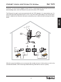
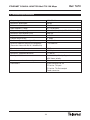
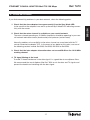
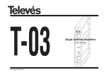
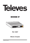
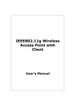
ETHERNET COAXIAL ADAPTOR
ETHERNET
ETH. AUX.
MxU T05 128 Mbps
TV
TV+Data
0234016 003
Ref. 7672
User Manual
© Copyright Televés S.A.
ETHERNET COAXIAL ADAPTOR MxU T05 128 Mbps
Ref. 7672
Important safety instructions
- Power sockets should be close to the equipment and easily accessible.
- Do not connect feed until the installation is complete.
- To disconnect the equipment from the feed grid, unplug the adaptor.
- Do not use oils, solvents, petrol, paint thinners or insecticides to clean this device.
- This device contains no user-repairable parts. Do not open as there is a risk of electric shock.
- Do not use the device near water, for example: bathtubs, washbasins, humid areas, swimming
pools, etc.
- Use the power feed recommended on the data plate.
- Unplug the grid adaptor under the following circumstances:
a) If the plug is damaged.
b) If the device has been in contact with water.
c) If the device is not functioning normally.
d) If the device has broken down.
This symbol indicates total compliance with EC marking
.
This symbol indicates the equipment should be used indoors.
This symbol indicates that the equipment complies with Class II equipment safety
requirements.
2
ETHERNET COAXIAL ADAPTOR MxU T05 128 Mbps
Ref. 7672
Page
1.- INTRODUCTION . . . . . . . . . . . . . . . . . . . . . . . . . . . . . . . . . . . . . . . . . . . . . . . . . . . . . . .
1.1 - Ethernet Coaxial Head Adaptor 128Mbps . . . . . . . . . . . . . . . . . . . . . . . . . . . .
1.2 - Technical specifications . . . . . . . . . . . . . . . . . . . . . . . . . . . . . . . . . . . . . . . . . .
1.3 - System requirements . . . . . . . . . . . . . . . . . . . . . . . . . . . . . . . . . . . . . . . . . . . .
4
4
4
4
2.- ADAPTOR PORTS . . . . . . . . . . . . . . . . . . . . . . . . . . . . . . . . . . . . . . . . . . . . . . . . . . . . .
2.1 - The Adaptor LEDs . . . . . . . . . . . . . . . . . . . . . . . . . . . . . . . . . . . . . . . . . . . . . . .
6
7
3.- MOUNTING OF THE ETHERNET-COAXIAL HEAD ADAPTOR 128MBPS . . . . . . . . . .
3.1 - Internet Connection through an External Router . . . . . . . . . . . . . . . . . . . . . . .
3.2 - Coaxial Network Connection within the Head . . . . . . . . . . . . . . . . . . . . . . . . .
3.3 - Coaxial Network Connection with a diplexer filter . . . . . . . . . . . . . . . . . . . . . .
3.4 - Connecting the Ethernet Coaxial User Adaptors to the power points . . . . . .
8
8
9
10
11
4.- SAMPLE INSTALLATIONS . . . . . . . . . . . . . . . . . . . . . . . . . . . . . . . . . . . . . . . . . . . . . . .
Shared Internet Access . . . . . . . . . . . . . . . . . . . . . . . . . . . . . . . . . . . . . . . . . . . . . . .
Videostreaming Service Implementation . . . . . . . . . . . . . . . . . . . . . . . . . . . . . . . . . .
Installation of Multiple Adaptors in Head . . . . . . . . . . . . . . . . . . . . . . . . . . . . . . . . .
12
12
13
14
5.- TECHNICAL SPECIFICATIONS . . . . . . . . . . . . . . . . . . . . . . . . . . . . . . . . . . . . . . . . . . .
16
6.- PROBLEM SOLVING . . . . . . . . . . . . . . . . . . . . . . . . . . . . . . . . . . . . . . . . . . . . . . . . . . .
17
3
ENGLISH
CONTENTS
ETHERNET COAXIAL ADAPTOR MxU T05 128 Mbps
Ref. 7672
1.- Introduction
1.1- Ethernet Coaxial-Head-Adaptor 128Mbps
The function of the "Ethernet - Coaxial Adaptor128Mbps" is the immediate and simple connection of multiple PCs to the coaxial network of your building or your ICT network. There is
no need for extra cables, Hubs or Switches. The data will be carried on your building or ICT
network’s TV distribution coaxial cable installation.
The Ethernet - Coaxial Adaptor 128Mbps enables network data transmission simultaneously
with that of the existing TV channels or services. This device is equipped with two standard F
connectors, an Ethernet port and a feed connector, and is able to transmit up to 72Mbps.
The Adaptor connects the data network access point established in the head (ADSL, LDMS,
Cable-modem, etc.) to each TV socket in your building through the coaxial cable.
1.2- Technical specifications
Connects a computer to an Internet access point, using your building’s existing coaxial
cable.
Easy to install, with no need to open up the PC or install any kind of driver.
Data transfer rate up to 72 Mbps
2 easy-to-read LED indicators showing the device’s status.
Connects a total of up to 31 PCs on your coaxial distribution network
No Hubs or Switches are required. The data is carried on the coaxial cable.
Shares high-velocity Internet access.
Sound muffling between head and sockets should in no case exceed 50 dB on the return
channel.
It supports Quality of Service for the implementation of a Video Streaming Service or VoIP
on the coaxial network.
1.3- System requirements
`To be able to use this device you must have Internet access equipment (ADSL, Cable
Modem, LMDS, etc...) with an Ethernet 802.3 network interface
The system is totally Plug&Play and requires no additional software or driver installation;
you merely have to connect the adaptor to the network interface corresponding to your
internet access equipment.
4
ETHERNET COAXIAL ADAPTOR MxU T05 128 Mbps
Ref. 7672
ENGLISH
To connect the Internet access equipment with the Ethernet-Coaxial Adaptor 128Mbps
you will need an Ethernet CAT-5 cable.
5
Ref. 7672
ETHERNET COAXIAL ADAPTOR MxU T05 128 Mbps
TV+Data
TV
ETH. AUX.
1
ETHERNET
1
0234016 003
2.- Adaptor Ports
2
3
4
5
Ethernet Aux
Through this port you can access the devices connected to the Ethernet port but will be
unable to communicate with the 7672 adaptor. This is the Ethernet port to be used for connecting other 7672 adaptors onto the head, creating additional data networks and preventing cross-communication between the different data networks.
2
Ethernet
The Ethernet port is an RJ-45 port for connecting your Coaxial Adaptor to the Ethernet
port on the router or Internet access modem. The connection between the Router and the
Adaptor is done with an Ethernet CAT-5 cable.
3
Feed connector
This connector enables device power feed through feed source Ref. 5029. There is also a jack
connector in the event that Ref. 5029 is unavailable.
4
RF IN
The F connector for TV signal input from the other components on the head.
5
RF Out
The F connector for data network+TV output. This is the connector for the coaxial network
that distributes the signals from the head to the different sockets in the building.
6
Ref. 7672
ETHERNET COAXIAL ADAPTOR MxU T05 128 Mbps
0234016 003
TV+Data
TV
2.1- The Adaptor LEDs
Coax. link
ETH. AUX.
The Ethernet Coaxial Adaptor 128 Mbps includes the following indicator LEDs:
1
Power
A yellow LED that illuminates when the device is connected to the feed source.
2
Coax. link
A green LED that will light up when the head adaptor is linked to a user adaptor. Once the
link has been established, in the event there is activity on the network this LED will blink,
showing that data are being transmitted/received.
7
ENGLISH
ETHERNET
Power
Ref. 7672
ETHERNET COAXIAL ADAPTOR MxU T05 128 Mbps
3.- Mounting of the Ethernet-Coaxial Head Adaptor 128Mbps
The following are instructions for connecting the Coaxial MxU Adaptor 128Mbps with the rest
of the head components.
Once it has been installed, you can connect the Ethernet-Coaxial Adaptor Ref. 7671 to any
socket in your distribution scheme, enabling you to access Internet.
3.1- Connecting to Internet through an External Router
For 7672 to enable Internet access, it should be connected to some device providing connectivity; the most usual method of access is by using an ADSL Router, a Cable Modem or a similar device. To do this, you must use a CAT-5 Ethernet cable.
1. Connect one end of the CAT-5 cable to the Ethernet Network interface at the Internet
access point.
ETH. AUX.
2. Connect the other end to the RJ-45 connector of the 7672.
Internet
ETHERNET
Cat-5 Cable
TV
TV+Data
Router
ADSL
0234016 003
TV Head
Distribution
Network
Tap
Ref. 7671
Slave
MxU
ETHE
-COA
RNET
X ADAP
Re
r
-COA
RNET
X ADAP
TER
00
we
8
ETHE
011
Po
de
k
Mo
nc
Lin
MxU
Sy
ax
Co
TER
234
00
011
Po
de
k
Mo
Sy
Co
ax
nc
Lin
234
we
r
Re
f.
f.
76
76
71
71
Ref. 7671
Slave
Ref. 7672
ETHERNET COAXIAL ADAPTOR MxU T05 128 Mbps
3.2- Connecting to the Coaxial Network inside the Head
You can integrate the Ethernet-Coaxial Adaptor with the rest of the head components. To do
this, proceed as follows:
ETHERNET
ETH. AUX.
ENGLISH
CLAC!
1
TV
TV+Data
0234016 003
2
Distribution
Network
Tap
Ref. 7671
Slave
MxU
ETHE
-COA
RNET
X ADAP
Re
r
00
011
we
Po
de
k
Mo
Lin
Co
nc
Sy
234
00
011
we
Po
234
ax
k
Lin
nc
Sy
Co
ax
de
Mo
r
Re
f.
f.
76
76
71
71
Ref. 7671
Slave
TER
MxU
ETHE
-COA
RNET
X ADAP
TER
1. Using an EMC Ref.5074 bridging connector, connect the F ‘RF IN’ connector to the front
module of the head. In the event it is a first module, you will have to connect a Ref. 4061
line terminator.
2. Connect the F ‘RF OUT’ connector to the next module on the head or, if it is the last
module on the head, connect it with the coaxial network input point.
Note: We recommend that the Ethernet-Coaxial Head Adaptor 128Mbps be the last serial component on the head before signal input on the coaxial network.
9
Ref. 7672
ETHERNET COAXIAL ADAPTOR MxU T05 128 Mbps
3.3- Connecting with the coaxial network using a diplexer filter
If there is no fixture for connecting the Adaptor to the head, or if you wish the data signal to be
injected into the network outside of the head, do the following:
1. Connect the signal that has been previously treated in the head to the 47-862 Mhz input
socket of the Ref. 7654 diplexer filter.
2. Connect the data signal from the Ethernet – Coaxial Adaptor 128Mbps to the 5-40 Mhz
input socket of the Ref. 7654 diplexer filter.
3. Connect the output of the diplexer filter to the coaxial network
ETHERNET
ETH. AUX.
Ref.
7672
Ref. 7654
TV
TV+Data
0234016 003
Network
Ref.
7671
MxU
OAX
NET-C
ETHER
00
Re
f.
k
de
Mo
Lin
c
Syn
ax
11
2340
Re
00
11
2340
Co
k
Lin
c
Syn
Co
ax
de
Mo
f.
r
we
1
Po
767
r
we
1
Po
767
Tap
Ref.
7671
TER
ADAP
MxU
OAX
NET-C
ETHER
TER
ADAP
Note: If no 7654 diplexer filter is available, simply mix the TV head with the data signal using a
mixer (for example Ref. 5150) although this may reduce the performance of the system if
there is presence of low frequency background noise generated by the head processors.
10
Ref. 7672
ETHERNET COAXIAL ADAPTOR MxU T05 128 Mbps
3.4- Connecting the Ethernet Coaxial User Adaptors to the sockets
The last step necessary is to connect the Ref. 7671 Coaxial Adaptor to the sockets of your
installation. For the purpose, do the following:
1. Connect the end of the coaxial cable to the TV outlet (Male CEI connector).
2. Connect the other end of the cable to the modem data input port (F Connector).
3. Check that the red Synch Mode light is on. If this light turns on when the adaptor is connected to the socket, this means it has connectivity with 7672 and therefore communication with the head has been correctly established.
4. Check that the socket you are using to connect the Adaptor will support the return channel (5-30Mhz). If you are in any doubt or are unsure of the characteristics of your TV socket, we recommend you use one of the following TV sockets: Ref.5232, Ref.5233,
Ref.5226 or Ref.5228.
As noted in the general technical specifications of the Coaxial Adaptor 128Mbps, the maximum sound attenuation between two connection points should be less than 50 dB on the 1228Mhz return channel.
Network
er
w
Po
11
40
23
e
Li
x
oa
C
Sy
nc
nk
M
od
00
Re
f.
76
71
Ref. 7671
Slave
Mx
AX
CO
ETERN
U ETH
TV
Socket
R
PTE
ADA
CEI +
adaptor CEI-F Cable
Ethernet
Cable
Now your coaxial network sockets have been transformed into data sockets!
11
ENGLISH
To connect the slave adaptor to one of the TV sockets:
Ref. 7672
ETHERNET COAXIAL ADAPTOR MxU T05 128 Mbps
4.- Installation Examples
Shared Internet Access
In the event that you wish to share Internet access, you will only have to connect the 7672 to
an ADSL router in such a way that the connection is shared among all the nodes of the coaxial
network.
It is necessary for the Internet router to provide all the services required by modem-connected
users, including DNS, DHCP, NAT, etc... In order to carry out a correct installation, check the
router manual of your Internet provider.
Since the RJ45 connector of the head adaptor is designed specifically for connecting to commuting components it will NOT be necessary to use a crossover cable for connecting the bus
converter and the broadband router.
7672
ETHERNET
ETH. AUX.
Cat-5
Cable
Internet
TV
TV+Data
0234016 003
Router
ADSL
Splitter
TV
Socket
11
Po
2340
de
k
Mo
c
Lin
Syn
ax
Co
Adaptor
7671
00
we
r
Re
f.
767
1
TV
Socket
MxU
OAX
NET-C
ETHER
TER
ADAP
Splitter
TV
Socket
TV
Socket
Adaptor
7671
MxU
OAX
NET-C
ETHER
r
TER
ADAP
00
we
12
OAX
NET-C
ETHER
11
Po
de
k
Mo
c
Lin
MxU
Syn
ax
Co
TER
ADAP
2340
00
11
Po
de
k
Mo
Syn
Co
ax
c
Lin
2340
we
r
Re
Re
f.
f.
767
767
1
1
Adaptor
7671
Ref. 7672
ETHERNET COAXIAL ADAPTOR MxU T05 128 Mbps
Videostreaming service implementation
The 7672 can be used to implement Videostreaming and/or TVIP (TV streaming on IP) services
in your building or ICT network.
ENGLISH
To do this, you need to install a VideoStream Server in the head and Set-top Boxes in each of
the apartments where Video is to be served.
Internet
Ref. 7672
Switch
Ethernet
ETHERNET
ETH. AUX.
Router
ADSL
TV
TV+Data
0234016 003
TV Head
VideoStream
Server
Set-top
Box
Splitter
TV
Socket
00
11
Po
de
k
Mo
c
Lin
Syn
Co
ax
Adaptor
7671
2340
we
r
Re
f.
767
1
TV
Socket
MxU
OAX
NET-C
ETHER
TER
ADAP
Splitter
TV
Socket
TV
Socket
Adaptor
7671
OAX
NET-C
ETHER
MxU
13
OAX
NET-C
ETHER
TER
ADAP
00
11
Po
de
k
Mo
c
Lin
ax
Co
TER
ADAP
Syn
r
00
we
11
Po
2340
de
k
Mo
c
Lin
Syn
ax
Co
MxU
2340
Re
f.
we
r
767
Re
1
f.
767
1
Adaptor
7671
Ref. 7672
ETHERNET COAXIAL ADAPTOR MxU T05 128 Mbps
Installation of Multiple Adaptors on the Head
In the event your installation has more than one coaxial downloading cable distributing the signals through head distributors, you can enhance the technical specifications of your data network by installing several adaptors on your Ref.7672 head.
Ref. 7672
Internet
Ref. 7672
Router
ADSL
ETHERNET
ETHERNET
ETH. AUX.
ETH. AUX.
Switch
Ethernet
TV
TV
TV+Data
0234016 003
TV+Data
0234016 003
TV Head
VideoStream
Server
Splitter
2W
FPA
Splitter
Splitter
Set-top
Box
Adaptor
7671
er
Ref
.
767
1
TV
Socket
de
TV
Socket
k
OAX
NET-C
ETHER
Co
ax
c
Lin
1
767
.
Ref
er
00
11
Pow
2340
de
k
Mo
c
Lin
Syn
ax
Co
MxU
ER
ADAPT
MxU
Adaptor
7671
14
OAX
NET-C
ETHER
ER
ADAPT
00
Network
11
Network
Pow
Ref. 7654
2340
Ref. 7654
Mo
Set-top
Box
Ref 7654
Syn
FPB
Ref. 7672
ETHERNET COAXIAL ADAPTOR MxU T05 128 Mbps
To do this, you have to link together several 7672s, connecting the Ethernet port of one of the
downloading cables with the Ethernet Aux port of the other 7672 adaptor.
ENGLISH
The Ethernet Aux port is not communicated with the 7672 adaptor it is connected to, but it is
communicated with the Ethernet port in such a way that traffic generated by each of the downloads is added to the Ethernet connector, preventing cross-communication among the downloads.
Ref. 7672
Ref. 7672
ETHERNET
ETH. AUX.
ETH. AUX.
Internet
ETHERNET
CAT-5
Ethernet
Cable
TV
TV+Data
0234016 003
Set-top
Box
Router
ADSL
TV
TV+Data
0234016 003
Network
Network
Splitter
Splitter
Adaptor
7671
TV
Socket
11
er
Pow
de
k
Mo
Co
Syn
ax
c
Lin
2340
1
767
.
Ref
er
00
11
Pow
2340
de
k
Mo
Syn
Co
ax
c
Lin
00
Ref
.
767
1
TV
Socket
MxU
OAX
NET-C
ETHER
ER
ADAPT
MxU
OAX
NET-C
ETHER
ER
ADAPT
Adaptor
7671
With this type of installation you can increase the number of users in the system as well as the
available bandwidth, while increasing Videostreaming and Internet access capacity.
15
ETHERNET COAXIAL ADAPTOR MxU T05 128 Mbps
Ref. 7672
5- Technical specifications
Output signal level
120 dBmV
Maximum attenuation
50 dB
Minimum attenuation
12 dB
Input frequency range
57 a 2150 MHz
Output frequency range
12 to 28 MHz (data) + 57 a 2150 MHz (TV)
Maximum consumption (12V)
400 mA
Input return losses
> 10dB
Output return losses
> 10dB
Maximum Spectral Density of Power
–60 dBm/Hz
Minimum Spectral Density of Reception
-110 dBm/Hz
(Gaussian noise with RX of -140dBm/Hz)
Maximum working temperature
45ºC
Transmission rate
128 Mpbs
Maximum supported distance
<= 800 m.
Quality of Service
VLAN 802.1p Priority Support +
UDP flows priority
Maximum number of user adaptors
31
Connectors
2 port Ethernet RJ-45
F Port for TV input
F Port for TV+Data output
Feed connector.
16
ETHERNET COAXIAL ADAPTOR MxU T05 128 Mbps
Ref. 7672
6.- PROBLEM SOLVING
1. Check that the slave adaptors have permanently lit up the Sync Mode LED.
In the event that the adaptors have not lit up the red Sync Mode LED indicating connectivity with the master.
2. Check that the return channel is available on your coaxial network
The return channel operating on 12-28Mhz frequencies should be operating in your coaxial network both downstream (head-socket) and upstream (socket-head).
Normally, problems of accessibility to the return channel are associated with the TV
socket connected to adaptor 7671. In the event of any doubt on this point, use one of
the following sockets instead: Ref.5232, Ref.5233, Ref.5226 or Ref.5228.
3. Check that the inter-adaptor attenuation does not exceed 50 dB on the 12-28 MHz
working channel.
4. TV signal filtering at the head
To avoid TV head interference in the data signal it is a good idea to use diplexer filters.
We recommend the use of diplexer filter Ref. 7654 to mix the data and TV signals and
prevent the head from interfering with the data signal.
17
ENGLISH
If you find connectivity problems in your data network, check the following points:
ETHERNET COAXIAL ADAPTOR MxU T05 128 Mbps
18
Ref. 7672
ETHERNET COAXIAL ADAPTOR MxU T05 128 Mbps
19
Ref. 7672
RED COMERCIAL - COMMERCIAL NETWORK
UNITED KINGDOM
FRANCE
GERMANY
TELEVES (UK) Ltd.
11 Hill Street Industrial Estate
Cwmbran, Gwent NP44 7PG
UNITED KINGDOM
Telephone: +44 1633 875821
Fax: +44 1633 866311
EMail: [email protected]
TELEVES FRANCE Sarl
1 Rue Louis de Broglie
Parc d'Activités de l'Esplanade
77400 St. Thibault des Vignes
FRANCE
Telephone: +33 1 6035 9210
Fax: +33 1 6035 9040
EMail: [email protected]
PREISNER KOMMUNIKATIONSTECHNIK GmbH
An den Kiesgruben 6, 73240 Wendlingen
DEUTSCHLAND
Telephone: +49 7024 55358
Fax: +49 7024 6295
EMail: [email protected]
CHINA
TELEVES CHINA
Unit 207-208, Building A, No 374
Wukang Rd, Xuhui District
200031 Shanghai
CHINA (P.R.C.)
Telephone: +86 21 6126 7620
Fax: +86 21 6466 6431
EMail: [email protected]
USA
TELEVES USA LLC.
9800 Mount Pyramid Court, Suite
400
80112 Englewood, CO
USA
Telephone : +1 303 256 6767
Fax : +1 303 256 6769
EMail: [email protected]
PORTUGAL
ITALY
MIDDLE EAST
TELEVES ELECTRONICA PORTUGUESA
Via Dr. Francisco Sa Carneiro, Lote 17
Zona Ind. Maia 1 Sector X
4470 Barca-Maia-Oporto
PORTUGAL
Telephone: +351 22 94 78900
Fax: +351 22 94 78900
EMail: [email protected]
TELEVES ITALIA Srl.
Via Liguria 24
2068 Peschiera Borromeo (MI)
ITALIA
Telephone: +39 02 5165 0604
Fax: +39 02 5530 7363
EMail: [email protected]
TELEVES MIDDLE EAST FZE
P.O. Box 17199 Jebel Ali Free Zone
Dubai
UNITED ARAB EMIRATES
Telephone: +971 48 834 344
Fax: +971 48 834 644
EMail: [email protected]
Oficinas Centrales / Head Office
Delegaciones / Subsidiaries
Sucursales / Distributors
Para conocer nuestra red de sucursales en el mundo, le rogamos consulte en nuestra pagina web
Please visit Televés web site to find your nearest Official Distributor
Rúa Benéfica de Conxo, 17
15706 - Santiago de Compostela
ESPAÑA (SPAIN)
Tel: +34 981 52 22 00 - Fax: +34 981 52 22 62
[email protected] - www.televes.com
Miembro de número del
Empresa
Registrada
ER 224/1/94