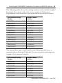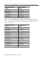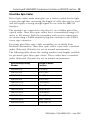
1
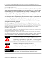
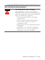
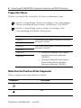
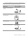
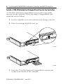
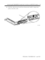
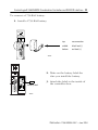
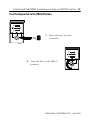
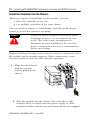
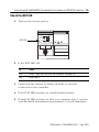
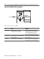
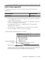
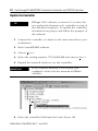
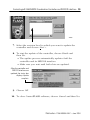
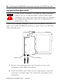
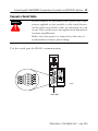
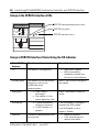
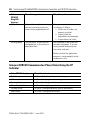
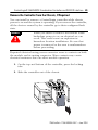
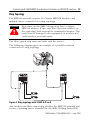
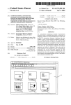
Installation Instructions
ControlLogix® 5560M03SE Combination
Controller and SERCOS interface
Catalog Number: 1756-L60M03SE
Introduction
The ControlLogix®5560M03SE controller is a 2-slot ControlLogix
controller that includes a 3-axis SERCOS interface™.
WARNING
!
An electrical arc can occur if you:
• insert or remove the controller while
backplane power is on
• connect or disconnect the battery
• connect or disconnect the serial cable with
power applied to this module or the serial
device on the other end of the cable
This could cause an explosion in hazardous
location installations. Make sure that power is
removed or the area is nonhazardous before
proceeding.
Publication 1756-IN593A-EN-P – June 2004
2 ControlLogix® 5560M03SE Combination Controller and SERCOS interface
Important User Information
Because of the variety of uses for the products described in this publication, those responsible
for the application and use of these products must satisfy themselves that all necessary steps
have been taken to assure that each application and use meets all performance and safety
requirements, including any applicable laws, regulations, codes and standards. In no event
will Rockwell Automation be responsible or liable for indirect or consequential damage
resulting from the use or application of these products.
Any illustrations, charts, sample programs, and layout examples shown in this publication are
intended solely for purposes of example. Since there are many variables and requirements
associated with any particular installation, Rockwell Automation does not assume
responsibility or liability (to include intellectual property liability) for actual use based upon
the examples shown in this publication.
Allen-Bradley publication SGI-1.1, Safety Guidelines for the Application, Installation and
Maintenance of Solid-State Control (available from your local Rockwell Automation office),
describes some important differences between solid-state equipment and electromechanical
devices that should be taken into consideration when applying products such as those
described in this publication.
Reproduction of the contents of this copyrighted publication, in whole or part, without written
permission of Rockwell Automation, is prohibited.
Throughout this publication, notes may be used to make you aware of safety considerations.
The following annotations and their accompanying statements help you to identify a potential
hazard, avoid a potential hazard, and recognize the consequences of a potential hazard:
WARNING
!
ATTENTION
!
IMPORTANT
Identifies information about practices or
circumstances that can cause an explosion in a
hazardous environment, which may lead to personal
injury or death, property damage, or economic loss.
Identifies information about practices or
circumstances that can lead to personal injury or
death, property damage, or economic loss.
Identifies information that is critical for successful
application and understanding of the product.
Publication 1756-IN593A-EN-P – June 2004
ControlLogix® 5560M03SE Combination Controller and SERCOS interface 3
Related Documentation
The following documents contain additional information concerning
related Allen-Bradley products.
For:
Read This Document:
Publication
Number
Installing a battery module
ControlLogix Battery Module
Installation Instructions
1756-IN576
Controller procedures
Logix5000 Controllers Common
Procedures
1756-PM001
Controller commands
Logix5000 Controllers General
Instructions Reference Manual
1756-RM003
System information
ControlLogix System User Manual
1756-UM001
ControlLogix motion
commands
Motion Instruction Set Reference
Manual
1756-RM007
Information on setup and
configuration
ControlLogix Motion Module
Setup and Configuration manual
1756-UM006
Installation, wiring, and
setup for the
1394C-SJTxx-D
1394 SERCOS Interface Multi Axis
Motion Control System
1394C-5.20
Information on integrating
the 1394 drive with SERCOS
1394 SERCOS Integration Manual
1394-IN024
Ultra3000 installation
Ultra3000 Hardware Installation
Manual
2098-IN003
Kinetix 6000 Module
installation
Kinetix 6000 Module Installation
Manual
2094-IN004
Kinetix 6000 installation
Kinetix 6000 Installation Manual
2094-IN001
Integrating the Kinetix 6000
with SERCOS
Kinetix 6000 Integration Manual
2094-IN002
Integrating the Ultra3000
with the 1756-MxxSE
Ultra3000 SERCOS Integration
Manual
2098-IN005
8720MC High Performance
Drive user information
8720MC High Performance Drive
User Manual
8720MC-UM001
Publication 1756-IN593A-EN-P – June 2004
4 ControlLogix® 5560M03SE Combination Controller and SERCOS interface
To obtain a copies of the above manuals:
If you want to:
Then:
view a manual
Visit either of these locations:
download a manual
• www.ab.com/manuals
• www.theautomationbookstore.com
purchase a printed
manual
Use one of these options:
• contact your local distributor or Rockwell Automation
representative
• visit www.theautomationbookstore.com and place an
order
• call 800.963.9548 (USA/Canada) or 001.320.725.1574
(outside USA/Canada)
Overview
The ControlLogix5560M03SE controller serves as a link between the
ControlLogix platform and intelligent drives. The communication link
between the controller and the drive(s) is via IEC/EN 61491 SErial
Real-time COmmunication System (SERCOS) using fiber optic
medium. Fiber optics assures reliable high speed data transmission
with excellent noise immunity, improved performance, and
elimination of interconnect wiring.
SERCOS is a real-time optical serial interface between the controller
and its associated drives to transmit periodic and non-periodic data. It
uses a ring topology with one master and multiple slaves (axes). The
3 Axis SERCOS interface lets the controller control 1 to 3 axes in
either position, velocity, or torque mode. It provides a cycle period of
0.5ms, 1ms, or 2ms depending on the number of axes. It provides a
ring data rate of 4 Mbaud or 8 Mbaud. The device meets ASA System
specifications.
Publication 1756-IN593A-EN-P – June 2004
ControlLogix® 5560M03SE Combination Controller and SERCOS interface 5
How to Handle ControlLogix Components
ATTENTION
!
Preventing Electrostatic Discharge
This equipment is sensitive to electrostatic
discharge, which can cause internal damage and
affect normal operation. Follow these guidelines
when you handle this equipment:
• Touch a grounded object to discharge
potential static.
• Wear an approved grounding wriststrap.
• Do not touch connectors or pins on
component boards.
• Do not touch circuit components inside the
equipment.
• If available, use a static-safe workstation.
• When not in use, store the equipment in
appropriate static-safe packaging.
Publication 1756-IN593A-EN-P – June 2004
6 ControlLogix® 5560M03SE Combination Controller and SERCOS interface
Prepare the Chassis
Before you install the controller, do these preliminary steps:
✓
Install a ControlLogix chassis according to the ControlLogix
Chassis Installation Instructions, publication 1756-IN080.
✓
Install a ControlLogix power supply according to the
corresponding installation instructions:
Install this power supply:
According to this publication:
1756-PA72
ControlLogix Power Supplies Installation Instructions,
publication 1756-5.67
1756-PB72
1756-PA75
1756-PB75
1756-PA75R
1756-PB75R
ControlLogix Power Supplies Installation Instructions,
publication 1756-5.78
• ControlLogix Redundant Power Supplies
Installation Instructions, publication
1756-IN573
• ControlLogix Redundant Power Supplies
Chassis Adapter Module Installation
Instructions, publication 1756-IN574
Make Sure that You Have All the Components
These components ship with the module:
Component:
Description:
1756-BA1 battery
key
Publication 1756-IN593A-EN-P – June 2004
ControlLogix® 5560M03SE Combination Controller and SERCOS interface 7
You may also use these components with the module:
And you want to:
Then use this component:
connect a device to the serial port of the
controller (e.g., connect a computer to the
controller)
1756-CP3 serial cable
42576
provide battery support for the controller
longer than the time that is available with
the 1756-BA1 battery
1756-BATM ControlLogix battery module
31298
add nonvolatile memory
1784-CF64 Industrial CompactFlash card
31376-M
connect the SERCOS interface to drives
Glass: 2090-SCVGx-x
Plastic: 2090-SCxPx-x
Publication 1756-IN593A-EN-P – June 2004
8 ControlLogix® 5560M03SE Combination Controller and SERCOS interface
Install a 1784-CF64 Industrial CompactFlash Card in the Controller
A 1784-CF64 Industrial CompactFlash card provides nonvolatile
memory for the controller. If you are using a CompactFlash card,
install the card as follows:
1. Lay the controller on its side with the front facing to the left.
2. Raise the locking clip all the way up.
31377-M
31378-M
3. Insert the 1784-CF64 Industrial CompactFlash card into the
socket at the bottom of the controller.
Publication 1756-IN593A-EN-P – June 2004
ControlLogix® 5560M03SE Combination Controller and SERCOS interface 9
4. Pull the clip forward and then downward until it snaps into
place over the card.
31379-M
Publication 1756-IN593A-EN-P – June 2004
10 ControlLogix® 5560M03SE Combination Controller and SERCOS interface
Connect a Battery
WARNING
!
When you connect or disconnect the battery an
electrical arc can occur. This could cause an
explosion in hazardous location installations. Be
sure that power is removed or the area is
nonhazardous before proceeding.
For Safety information on the handling of lithium
batteries, including handling and disposal of
leaking batteries, see Guidelines for Handling
Lithium Batteries, publication AG 5-4.
ATTENTION
!
Connect only a 1756-BA1 battery or a 1756-BATM
battery module to the controller. If you connect a
different battery, you may damage the controller.
To maintain the memory of the controller while the controller is
without power, either use nonvolatile memory or connect a battery:
If your controller:
And you want to:
has nonvolatile
memory
does not have
nonvolatile
memory
Then:
A battery is permitted but not
required.
maintain memory only while the
controller is in the chassis
Connect a 1756-BA1 battery or
a 1756-BATM battery module.
maintain memory while the
controller is out of the chassis
Connect a 1756-BA1 battery.
To connect a 1756-BATM battery module, see the ControlLogix
Battery Module Installation Instructions, publication 1756-IN576.
Publication 1756-IN593A-EN-P – June 2004
ControlLogix® 5560M03SE Combination Controller and SERCOS interface 11
To connect a 1756-BA1 battery:
1. Install a 1756-BA1 battery.
top
no connection
middle
black lead (-)
bottom
red lead (+)
42523
2. Write on the battery label the
date you install the battery.
battery label
3. Attach the label to the inside of
the controller door.
42524
Publication 1756-IN593A-EN-P – June 2004
12 ControlLogix® 5560M03SE Combination Controller and SERCOS interface
ATTENTION
!
ATTENTION
!
To prevent possible battery leakage, even if the
BAT LED is off, replace a 1756-BA1 battery
according to the following schedule:
If the temperature 1 in.
below the chassis is:
Replace the battery within:
0° to 35° C
No replacement is required until
the BAT LED turns on.
36° to 40° C
3 years
41° to 45° C
2 years
46° to 50° C
16 months
51° to 55° C
11 months
56° to 60° C
8 months
Store batteries in a cool, dry environment. We
recommend 25°C with 40% to 60% relative
humidity. You may store batteries for up to 30
days between -45° to 85°C, such as during
transportation. To avoid possible leakage, do not
store batteries above 60°C for more than 30 days.
Publication 1756-IN593A-EN-P – June 2004
ControlLogix® 5560M03SE Combination Controller and SERCOS interface 13
Turn the Keyswitch to the PROG Position
1. Insert the key into the
controller.
42899
2. Turn the key to the PROG
position.
42898
Publication 1756-IN593A-EN-P – June 2004
14 ControlLogix® 5560M03SE Combination Controller and SERCOS interface
Install the Controller into the Chassis
When you install a ControlLogix combo module, you can:
• place the controller in any slot
• use multiple controllers in the same chassis
You can install or remove a ControlLogix controller while chassis
power is on and the system is operating.
WARNING
!
When you insert or remove the module while
backplane power is on, an electrical arc can
occur. This could cause an explosion in
hazardous location installations. Be sure that
power is removed or the area is nonhazardous
before proceeding.
Repeated electrical arcing causes excessive wear to contacts on both
the module and its mating connector. Worn contacts may create
electrical resistance that can affect module operation.
1. Align the circuit board
with the top and
bottom guides in the
chassis.
2. Slide the module into the chassis. The controller is fully
installed when it is flush with the power supply or other
installed modules and the top and bottom latches are engaged.
Publication 1756-IN593A-EN-P – June 2004
ControlLogix® 5560M03SE Combination Controller and SERCOS interface 15
Check the BAT LED
1. Turn on the chassis power.
Logix5560M03SE TM
I/O
RUN
RS232
FORCE
BAT
BAT LED
RUN
SERCOS interfaceTM
OK
REM
PROG
CP
OK
2. Is the BAT LED off?
If:
Then:
Yes
Go to “Check the OK LED of the Controller” on page 16.
No
Go to step 3.
3. Check that the battery or battery module is correctly
connected to the controller.
4. If the BAT LED remains on, install another battery.
5. If the BAT LED remains on after you complete step 4, contact
your Rockwell Automation representative or local distributor.
Publication 1756-IN593A-EN-P – June 2004
16 ControlLogix® 5560M03SE Combination Controller and SERCOS interface
Check the OK LED of the Controller
Logix5560M03SE TM
I/O
RUN
RS232
FORCE
BAT
RUN
SERCOS interfaceTM
OK
REM
PROG
CP
OK
OK LED
What color is the OK LED?
If:
Then:
Actions:
solid green
The controller is OK and its
firmware has been updated.
No further actions are required.
However, the revision of firmware
must be compatible with your
revision of RSLogix 5000 software.
flashing red
The controller is OK but it requires a
firmware update.
Go to “Install a Firmware Upgrade
Kit” on page 17.
solid red
The controller is not operational.
Contact your Rockwell Automation
representative or local distributor.
Publication 1756-IN593A-EN-P – June 2004
ControlLogix® 5560M03SE Combination Controller and SERCOS interface 17
Install a Firmware Upgrade Kit
To update the firmware of the controller, first install a firmware
upgrade kit.
For this controller
Use this revision:
1756-L60M03SE
13.x or later
• The upgrade kit includes the firmware for both the controller
and its SERCOS interface.
• Make sure that the firmware revision is compatible with your
revision of RSLogix 5000 software.
• An upgrade kit ships on a supplemental CD along with
RSLogix 5000 software.
• To download an upgrade kit, go to www.ab.com. Choose
Product Support. Choose Firmware Updates.
In RSLinx software, the controller shows up as 2 devices.
ControlLogix5560M03SE
controller
SERCOS interface
You update only the left-hand slot (controller). The update automatically includes both
the controller (left-hand slot) and its SERCOS interface (right-hand slot).
Publication 1756-IN593A-EN-P – June 2004
18 ControlLogix® 5560M03SE Combination Controller and SERCOS interface
Update the Controller
TIP
RSLogix 5000 software, revision 10.0 or later, lets
you update the firmware of a controller as part of
the download sequence. To update the controller,
download your project and follow the prompts of
the software.
1. Connect the controller or chassis to the same network as your
workstation.
2. Start ControlFLASH software.
3. Choose Next >.
4. Select the catalog number 1756-L60M03SE and choose Next >.
5. Expand the network until you see the controller.
IMPORTANT
If the required network is not shown, first
configure a driver for the network in RSLinx
software.
6. Select the controller (left-hand slot) and choose OK.
Publication 1756-IN593A-EN-P – June 2004
ControlLogix® 5560M03SE Combination Controller and SERCOS interface 19
42900
7. Select the revision level to which you want to update the
controller and choose Next >.
8. To start the update of the controller, choose Finish and
then Yes.
• The update process automatically updates both the
controller and its SERCOS interface.
• Make sure you wait until both slots are updated.
After the controller and
SERCOS interface are
updated, the status box
displays Update
complete.
9. Choose OK.
10. To close ControlFLASH software, choose Cancel and then Yes.
Publication 1756-IN593A-EN-P – June 2004
20 ControlLogix® 5560M03SE Combination Controller and SERCOS interface
Connect the Fiber Optic Cables
ATTENTION
!
Under certain conditions, viewing the optical port may
expose the eye to hazard. When viewed under some
conditions, the optical port may expose the eye beyond
the maximum permissible exposure recommended in
ANSI Z136.2, 1993.
Under most viewing conditions, there is no eye hazard. The fiber
optics used with the SERCOS interface is rated Class 1 for IEC LED
Safety Classification.
receiver
transmitter
1. Remove the protective end caps from the receiver and
transmitter of the SERCOS interface.
2. Insert each fiber optic cable into the appropriate connector
and screw on finger tight. The cable that emits light is the
transmitter.
Publication 1756-IN593A-EN-P – June 2004
ControlLogix® 5560M03SE Combination Controller and SERCOS interface 21
Connect a Serial Cable
WARNING
!
If you connect or disconnect the serial cable with
power applied to this module or the serial device
on the other end of the cable, an electrical arc can
occur. This could cause an explosion in hazardous
location installations.
Make sure that power is removed or the area is
nonhazardous before proceeding.
Use the serial port for RS-232 communication.
42575
serial port
Publication 1756-IN593A-EN-P – June 2004
22 ControlLogix® 5560M03SE Combination Controller and SERCOS interface
To connect a workstation to the serial port, use one of these cables:
• 1756-CP3 serial cable
• 1747-CP3 cable from the SLC product family (If you use this
cable, the controller door may not close.)
workstation end
controller end
42576
If you make your own serial cable:
• Limit the length to 15.2m (50 ft).
• Wire the connectors as follows:
Workstation
Controller
1 CD
1 CD
2 RDX
2 RDX
3 TXD
3 TXD
4 DTR
4 DTR
COMMON
COMMON
6 DSR
6 DSR
7 RTS
7 RTS
8 CTS
8 CTS
9
9
• Attach the shield to both connectors
Publication 1756-IN593A-EN-P – June 2004
42231
B
Yes
No
Do you want to prevent
RSLogix 5000 software from:
• changing the mode
• downloading a project
• performing online edits
Do you want to prevent
RSLogix 5000 software from
changing the mode?
B This includes Message (MSG) instructions.
A Outputs revert to their configured state for Program mode.
No
Do you want the logic to
control the output devices?
Yes
Do you want to execute the
logic in the controller?
No
Yes
Yes
No
Yes
No
1. Turn the keyswitch to REM.
2. Go online with
RSLogix 5000 software and
choose Test mode.
Turn the keyswitch to RUN
(Run mode).
Turn the keyswitch to RUN
and then to REM
(Remote Run mode).
Turn the keyswitch to PROG
(Program mode).
Turn the keyswitch to PROG
and then to REM
(Remote Program mode).
• All modes send and receive data in response to a message from another controller.
• All modes produce and consume tags.
Do you need to schedule a
ControlNet network?
Important
Choose the Operating Mode of the Controller
A
A
A
ControlLogix® 5560M03SE Combination Controller and SERCOS interface 23
Publication 1756-IN593A-EN-P – June 2004
24 ControlLogix® 5560M03SE Combination Controller and SERCOS interface
Interpret Controller LEDs
Logix5560M03SE TM
controller LEDs
Indicator
RUN
I/O
Force
I/O
RUN
RS232
FORCE
BAT
RUN
SERCOS interfaceTM
OK
REM
Color
PROG
CP
OK
Description
Off
Controller is in Program or Test mode.
Solid Green
Controller is in RUN mode.
Off
Either:
• There are no devices in the I/O
configuration of the controller.
• The controller does not contain a
project.
Solid Green
Controller is communicating with all of the
devices in its I/O configuration.
Flashing Green
One or more devices in the I/O configuration of
the controller are not responding.
Flashing Red
The chassis is bad. Replace the chassis.
Off
• No tags contain I/O force values
• I/O forces are inactive (disabled).
Solid Amber
• I/O forces are active (enabled).
• I/O force values may or may not exist.
Flashing Amber
Publication 1756-IN593A-EN-P – June 2004
One or more input or output addresses have
been forced to an On or Off state, but the
forces have not been enabled.
ControlLogix® 5560M03SE Combination Controller and SERCOS interface 25
Indicator
Color
Description
RS232
Off
There is no activity.
Solid Green
Data is being received or transmitted.
Off
The battery supports memory.
Solid Red
Either the battery is not installed or it is 95%
discharged and should be replaced.
Off
No power is applied.
Flashing Red
If controller is new, then it requires a firmware
update.
BAT
OK
If controller is not new, then a major fault has
occurred. To clear the fault either:
• Turn the keyswitch to PROG then to
RUN then to PROG.
• Go online with RSLogix 5000
software.
You may also have to download the project to
the controller.
Solid Red
The controller detected a non-recoverable
fault, so it cleared the project from memory. To
recover:
1. Cycle power to the chassis.
2. Download the project.
3. Change to RUN mode.
If the OK LED remains solid red, contact your
Rockwell Automation representative or local
distributor.
Solid Green
The controller is OK.
Flashing Green
The controller is storing or loading a project to
or from nonvolatile memory.
Publication 1756-IN593A-EN-P – June 2004
26 ControlLogix® 5560M03SE Combination Controller and SERCOS interface
Interpret the SERCOS interface LEDs
Logix5560M03SE TM
SERCOS communication phase status
SERCOS ring status
I/O
RUN
RS232
FORCE
BAT
RUN
SERCOS interfaceTM
OK
REM
PROG
CP
OK
SERCOS interface status
Interpret SERCOS Interface Status Using the OK Indicator
If the OK LED
displays:
Then the module status is:
Off
The module is not operating.
Flashing green
The module has passed internal
diagnostics, but has not
established active
communications.
Take this action:
• Apply chassis power.
• Verify the module is
completely inserted into
the chassis and backplane.
None, if you have not configured
the module.
Solid green
• Data is being
exchanged.
• The module is in the
normal operating state.
None. The module is ready for
action.
Flashing red
• A major recoverable
failure has occurred.
• An NVS update is in
progress.
If an NVS update is in progress,
complete the NVS update.
Solid red
A potential nonrecoverable fault
has occurred.
Publication 1756-IN593A-EN-P – June 2004
If an NVS update is not in
progress: Reboot
• Reboot the module.
• If the solid red persists,
replace the module.
ControlLogix® 5560M03SE Combination Controller and SERCOS interface 27
Interpret SERCOS Ring Status
If the
SERCOS
Ring LED
displays:
Then the ring status is:
Take this action:
Solid green
The ring, drive, and axes are
configured and are actively
communicating through to the
nodes on the ring.
None.
Flashing red
The module has detected a setup
or configuration fault with the
ring.
Check your system setup and
configuration as follows:.
• Ensure drive and axes
addresses are correct.
• Remove excess axes from
ring.
• Make sure application
program has selected the
proper Ring Cycle Period
and Baud Rate.
Solid red
The module has detected a
hardware or installation fault
with the ring.
Check your system hardware and
installation as follows:
• Make sure all cables are
properly installed.
• Make sure cable is of the
correct type and length.
• Make sure application
program has configured
the module’s ring transmit
level to High when using
specified cables.
• Make sure the drive’s
transmit levels are set
appropriately.
• Inspect cables for
degradation.
• Inspect drives for any
faults and correct them.
Publication 1756-IN593A-EN-P – June 2004
28 ControlLogix® 5560M03SE Combination Controller and SERCOS interface
If the
SERCOS
Ring LED
displays:
Then the ring status is:
Take this action:
Off
The module has detected no ring
data on its receiver or has not
successfully completed phase 2.
Check your system and
installation as follows:
• Make sure all cables are
properly installed
• Inspect cable for
degradation and breakage.
• Inspect drives for faults.
Flashing green
The ring, drive, or axes are not
configured but, at least one has
been identified.
Not a problem if the system has
not been configured. If you are
having trouble configuring the
ring, drive, and axes:
Make sure that the application
program is setup properly for the
equipment in use.
Interpret SERCOS Communication Phase Status Using the CP
Indicator
If the CP LED displays:
Then the status is:
Solid Orange
In Phase -1: Autobaud detection in progress.
OFF
In Phase 0: looking for a closed ring.
Flashing Red
In Phase 1: looking for active nodes.
Alternating Red/Green
In Phase 2: configuring nodes for communication.
Flashing Green
In Phase 3: configuring device specific parameters
Solid Green
In Phase 4: configured and active.
Publication 1756-IN593A-EN-P – June 2004
ControlLogix® 5560M03SE Combination Controller and SERCOS interface 29
Remove the Controller from the Chassis, If Required
You can install or remove a ControlLogix controller while chassis
power is on and the system is operating. If you remove the controller,
all the devices owned by the controller go to their configured fault
state.
WARNING
!
When you insert or remove the module while
backplane power is on, an electrical arc can
occur. This could cause an explosion in
hazardous location installations. Be sure that
power is removed or the area is nonhazardous
before proceeding.
Repeated electrical arcing causes excessive wear to contacts on both
the module and its mating connector. Worn contacts may create
electrical resistance that can affect module operation.
1. On the top and bottom of the controller, press the locking
tabs.
2. Slide the controller out of the chassis.
Publication 1756-IN593A-EN-P – June 2004
30 ControlLogix® 5560M03SE Combination Controller and SERCOS interface
Fiber Optic Transmission
The fiber optic transmitter for the SERCOS interface 3 Axis module
uses a 650nm wavelength. This produces a visible light from the port
and is a determinant in factoring maximum cable lengths. The high
light output lets you use both plastic optical fiber (POF) and Hard
Clad Silica (HCS®) cables.
Fiber Optic Cables
The SERCOS interface is connected to the drive(s) via a fiber optic
cable. These cables can be either made of plastic or glass. For more
information about the care, handling, and installation of fiber optic
cables see the Fiber Optic Cable Installation and Handling
Instructions, publication number 2090-IN010x-EN-P.
Plastic Fiber Optic Cables
The modules are connected to the drive(s) via a 1000µm plastic
simplex fiber optical cable. Plastic fiber optic cables have a
transmission range of 1 meter to 32 meters. Both the transmitter and
receiver connections are made using a F-SMA standard plug that
conforms to the F-SMA screw type connector.
Pre-made plastic fiber optic cable assemblies are available from
Rockwell Automation. Plastic fiber optic cables come in a variety of
jackets depending on application environments. The cable is
available without a jacket (Chlorinated Polyethylene) for use inside
an electrical cabinet, a standard jacket (Polyvinyl Chloride) for use
outside of electrical cabinets, and a nylon jacket for use in harsh
environments.
Publication 1756-IN593A-EN-P – June 2004
ControlLogix® 5560M03SE Combination Controller and SERCOS interface 31
The following table shows the catalog numbers and available lengths
for plastic fiber optic cables that are not jacketed (Chlorinated
Polyethylene) and should be used only within an electrical cabinet.
Allen-Bradley Catalog
Number
Length in meters
(inches)
2090-SCEP0-1
0.1 m, (4 in)
2090-SCEP0-3
0.3 m, (12 in)
2090-SCEP0-9
0.9 m, (35 in)
2090-SCEP1-0
1 m (39 in)
2090-SCEP3-0
3 m (118 in)
2090-SCEP5-0
5 m (197 in)
2090-SCEP8-0
8 m (315 in)
2090-SCEP10-0
10 m (394 in)
2090-SCEP15-0
15 m (591 in)
2090-SCEP20-0
20 m (787 in)
2090-SCEP25-0
25 m (984 in)
2090-SCEP32-0
32 m (1260 in)
The plastic fiber optic cables listed in the following table have a
standard jacket (Polyvinyl Chloride) for use in normal environments
outside of an electrical cabinet.
Allen-Bradley Catalog
Number
Length in meters
(inches)
2090-SCVP0-1
0.1 m, (4 in)
2090-SCVP0-3
0.3 m, (12 in)
2090-SCVP0-9
0.9 m, (35 in)
2090-SCVP1-0
1 m (39 in)
2090-SCVP3-0
3 m (118 in
2090-SCVP5-0
5 m (197 in)
2090-SCVP8-0
8 m (315 in)
Publication 1756-IN593A-EN-P – June 2004
32 ControlLogix® 5560M03SE Combination Controller and SERCOS interface
Allen-Bradley Catalog
Number
Length in meters
(inches)
2090-SCVP10-0
10 m (394 in)
2090-SCVP15-0
15 m (591 in)
2090-SCVP20-0
20 m (787in)
2090-SCVP25-0
25 m (984 in)
2090-SCVP32-0
32 m (1260 in)
If your cables are going to run through a harsh environment, the
cable should be appropriately jacketed. The following table contains
the catalog numbers and lengths for nylon jacketed cables for use in
harsh environments.
Allen-Bradley Catalog
Number
Length in meters
(inches)
2090-SCNP0-1
0.1 m, (4 in)
2090-SCNP0-3
0.3 m, (12 in)
2090-SCNP0-9
0.9 m, (35 in)
2090-SCNP1-0
1 m, (39 in)
2090-SCNP3-0
3 m, (118 in)
2090-SCNP5-0
5 m (197 in)
2090-SCNP8-0
8 m (315 in)
2090-SCNP10-0
10 m (394 in)
2090-SCNP15-0
15 m (591 in)
2090-SCNP20-0
20 m (787 in)
2090-SCNP25-0
25 m (984 in)
2090-SCNP32-0
32 m (1260 in)
Publication 1756-IN593A-EN-P – June 2004
ControlLogix® 5560M03SE Combination Controller and SERCOS interface 33
Glass Fiber Optic Cables
Fiber Optic cables made from glass are a better conduit for the light
to pass through thus increasing the length of cable that may be used
and still supply a strong enough signal for use with the SERCOS
interface.
The modules are connected to the drive(s) via a 200µm glass fiber
optical cable. Glass fiber optic cables have a transmission range of 1
meter to 200 meters. Both the transmitter and receiver connections
are made using a F-SMA standard plug that conforms to the F-SMA
screw type connector.
Pre-made glass fiber optic cable assemblies are available from
Rockwell Automation. Glass fiber optic cables come with a standard
jacket (Polyvinyl Chloride) for use in normal environments.
The following table shows the catalog numbers and lengths available
for pre-made glass fiber optic cables. These cables have a standard
jacket (Polyvinyl Chloride) for use in normal environments.
Allen-Bradley Catalog
Number
Length in meters
(inches)
2090-SCVG1-0
1 m (39 in)
2090-SCVG3-0
3 m (118 in)
2090-SCVG5-0
5 m (197 in)
2090-SCVG8-0
8 m (315 in)
2090-SCVG10-0
10 m (394 in)
2090-SCVG15-0
15 m (591 in)
2090-SCVG20-0
20 m (787 in)
2090-SCVG25-0
25 m (984 in)
2090-SCVG32-0
32 m (1260 in)
2090-SCVG50-0
50m (1970 in)
2090-SCVG100-0
100m (3937 in)
Publication 1756-IN593A-EN-P – June 2004
34 ControlLogix® 5560M03SE Combination Controller and SERCOS interface
Cable Connector Handling and Maintenance
When cables are not in use, keep the ends covered with the dust
covers that came with the cables. This helps to keep dust and small
particles from blocking the optic path. Good system performance is
dependent on clean port optics and cable ferrules to avoid
obstructing the optical path. Clean compressed air is often sufficient
to remove particles of dirt.
ATTENTION
!
The small junction size inherent in the design of
these components increases the components’
susceptibility to damage from electrostatic
discharge (ESD). It is advised that normal static
precautions be taken in handling and assembly
of these components to prevent damage and/or
degradation which can be induced by ESD.
Supported Drives
The following Allen-Bradley drives are supported by the SERCOS
interface motion modules.
Catalog Number
Description
1394-SJT05-D
1394 5kW SERCOS Interface 460V drive
1394-SJT10-D
1394 10kW SERCOS Interface 460V drive
1394-SJT22-D
1394 22kW SERCOS Interface 460V drive
2094-AC05-M01
Kinetix 6000TM 230VAC ,IAM, 3kW PS, 9A Cont, 17A Peak
2094-AC05-MP5
Kinetix 6000, 230VAC ,IAM, 3kW PS, 5A Cont, 10A Peak
2094-AC09-M02
Kinetix 6000, 230VAC ,IAM, 6kW PS, 15A Cont, 30A Peak
2094-AC16-M03
Kinetix 6000, 230VAC ,IAM, 15kW PS, 24A Cont, 49A Peak
2094-AC32-M05
Kinetix 6000, 230VAC ,IAM, 23kW PS, 49A Cont, 98A Peak
2094-AM01
Kinetix 6000, 230VAC ,AM, 9A Cont, 17A Peak
Publication 1756-IN593A-EN-P – June 2004
ControlLogix® 5560M03SE Combination Controller and SERCOS interface 35
Catalog Number
Description
2094-AM02
Kinetix 6000, 230VAC ,AM, 15A Cont, 30A Peak
2094-AM03
Kinetix 6000, 230VAC ,AM, 24A Cont, 49A Peak
2094-AM05
Kinetix 6000, 230VAC ,AM, 49A Cont, 98A Peak
2094-AMP5
Kinetix 6000, 230VAC ,AM, 5A Cont, 10A Peak
2094-BC01-M01
Kinetix 6000, 460VAC, IAM, 6kW PS, 9A Cont, 13A Peak
2094-BC01-MP5
Kinetix 6000, 460VAC, IAM, 6kW PS, 4A Cont, 6A Peak
2094-BC02-M02
Kinetix 6000, 460VAC, IAM, 15kW PS, 15A Cont, 22A Peak
2094-BC04-M03
Kinetix 6000, 460VAC, IAM, 30kW PS, 30A Cont, 45A Peak
2094-BC07-M05
Kinetix 6000, 460VAC, IAM, 45kW PS, 49A Cont, 73A Peak
2094-BM01
Kinetix 6000, 460VAC, AM, 9A Cont, 13A Peak
2094-BM02
Kinetix 6000, 460VAC, AM, 15A Cont, 22A Peak
2094-BM03
Kinetix 6000, 460VAC, AM, 30A Cont, 45A Peak
2094-BM05
Kinetix 6000, 460VAC, AM, 49A Cont, 79A Peak
2094-BMP5
Kinetix 6000, 460VAC, AM, 4A Cont, 6A Peak
2098-DSD-005-SE
Ultra3000TM 0.5kW SERCOS Interface 230VDrive
2098-DSD-010-SE
Ultra30001kW SERCOS Interface 230VDrive
2098-DSD-020-SE
Ultra3000 2kW SERCOS Interface 230VDrive
2098-DSD-030-SE
Ultra3000 3kW SERCOS Interface 230VDrive
2098-DSD-075-SE
Ultra3000 7.5kW SERCOS Interface 230VDrive
2098-DSD-150-SE
Ultra3000 15kW SERCOS Interface 230VDrive
2098-DSD-HV030-SE
Ultra3000 3kW, 460VAC SERCOS Interface 460V drive
2098-DSD-HV050-SE
Ultra3000 5kW, 460VAC SERCOS Interface 460V drive
2098-DSD-HV100-SE
Ultra3000 10kW, 460VAC SERCOS Interface 460V drive
2098-DSD-HV150-SE
Ultra3000 15kW, 460VAC SERCOS Interface 460V drive
2098-DSD-HV220-SE
Ultra3000 22kW, 460VAC SERCOS Interface 460V drive
8720MC-B014
8720MC, 460VAC/750VDC, SERCOS Drive, 14A Cont, 21A Peak
Publication 1756-IN593A-EN-P – June 2004
36 ControlLogix® 5560M03SE Combination Controller and SERCOS interface
Catalog Number
Description
8720MC-B021
8720MC, 460VAC/750VDC, SERCOS Drive, 21A Cont, 32A Peak
8720MC-B027
8720MC, 460VAC/750VDC, SERCOS Drive, 27A Cont, 41A Peak
8720MC-B034
8720MC, 460VAC/750VDC, SERCOS Drive, 34A Cont, 51A Peak
8720MC-B042
8720MC, 460VAC/750VDC, SERCOS Drive, 42A Cont, 63A Peak
8720MC-B048
8720MC, 460VAC/750VDC, SERCOS Drive, 48A Cont, 72A Peak
8720MC-D065
8720MC, 750VDC, SERCOS Drive, 65A Cont, 98A Peak
8720MC-D078
8720MC, 750VDC, SERCOS Drive, 78A Cont, 117A Peak
8720MC-D097
8720MC, 750VDC, SERCOS Drive, 97A Cont, 145A Peak
8720MC-D120
8720MC, 750VDC, SERCOS Drive, 120A Cont, 180A Peak
8720MC-D149
8720MC, 750VDC, SERCOS Drive, 149A Cont, 224A Peak
8720MC-D0180
8720MC, 750VDC, SERCOS Drive, 180A Cont, 270A Peak
Publication 1756-IN593A-EN-P – June 2004
ControlLogix® 5560M03SE Combination Controller and SERCOS interface 37
Ring Topology
The SERCOS network consists of a Master SERCOS interface and
multiple drives connected in a ring topology.
ATTENTION
!
Each drive on the SERCOS ring must have a unique
SERCOS address. If two axes have the same address on
the same ring, both respond to commanded motion. This
could lead to damage to the equipment or product and
could result in personal injury.
The fiber optical ring starts and ends with the master.
The following diagram gives an example of a possible network
connected in a ring topology.
Logix5550
POWER
SERCOS interface
I/O
rs232
OK
BAT
RUN REM PROG
RUN
OK
Tx
Rx
Figure 1 Ring topology with 1394C-SJTxx-D
Any break in the fiber optical ring disables the SERCOS network and
creates a warning that is identified by the SERCOS Ring Status LED.
Publication 1756-IN593A-EN-P – June 2004
38 ControlLogix® 5560M03SE Combination Controller and SERCOS interface
Specifications – 1756-L60M03SE Controller
The following specifications apply to the 1756-L60M03SE controller:
Description:
Value:
Memory
Data and Logic(1)
750K bytes
I/O(2)
478K bytes
Nonvolatile(3)
Yes
Backplane Current
Power Dissipation
@5.1V dc
1.3A
@24V dc
6mA
3.5W
Thermal Dissipation
11.9 BTU/hr
Weight
0.52 kg (18.34 oz).
Operating Temperature
IEC 60068-2-1 (Test Ad, Operating Cold),
IEC 60068-2-2 (Test Bd, Operating Dry Heat),
IEC 60068-2-14 (Test Nb, Operating Thermal Shock):
• 0° to 60° C (32 to 140° F)
Storage Temperature
IEC 60068-2-1 (Test Ab, Un-packaged Non-operating Cold),
IEC 60068-2-2 (Test Bb, Un-packaged Non-operating Dry Heat),
IEC 60068-2-14 (Test Na, Un-packaged Non-operating Thermal Shock):
• -40° to 85° C (-40 to 185° F)
Relative Humidity
IEC 60068-2-30 (Test Db, Un-packaged Non-operating
Damp Heat):
• 5% to 95% noncondensing
Vibration
IEC60068-2-6 (Test Fc, Operating):
• 2g @ 10-500Hz
Operating Shock
IEC60068-2-27 (Test Ea, Unpackaged Shock):
• 30g
Non-Operating Shock
IEC60068-2-27 (Test Ea, Unpackaged Shock):
• 50g
Emissions
CISPR 11:
• Group 1, Class A
Publication 1756-IN593A-EN-P – June 2004
ControlLogix® 5560M03SE Combination Controller and SERCOS interface 39
Description:
Value:
ESD Immunity
IEC 61000-4-2:
• 4kV contact discharges
• 8kV air discharges
Radiated RF Immunity
IEC 61000-4-3:
• 10V/m with 1kHz sine-wave 80%AM from 80MHz to
2000MHz
• 10V/m with 200Hz 50% Pulse 100%AM at 900Mhz
• 10V/m with 200Hz 50% Pulse 100%AM at 1890Mhz
EFT/B immunity
IEC 61000-4-4:
• ±4kV at 2.5kHz on communications ports
Surge Transient Immunity
IEC 61000-4-5:
• ±2kV line-earth(CM) on communications ports
Conducted RF Immunity
IEC 61000-4-6:
• 10Vrms with 1kHz sine-wave 80%AM from 150kHz to 80MHz
Enclosure Type Rating
none (open-style)
Isolation Voltage
50V continuous
Tested to withstand 707V dc for 60 seconds
Wiring Category(4)
2 - on communications ports
Programming Cable
1756-CP3 or 1747-CP3 serial cable
category 3(4)
Replacement Battery
Number of Drives
For this component:
Use this battery:
1756-L60M03SE controller
1756-BA1 (0.59g lithium)
1756-BATM battery module
1756-BATA (10g lithium)
• up to 3 SERCOS interface drives via the integral SERCOS
interface of the controller
• up to 3 additional SERCOS interface drives or analog drives by
adding modules to the chassis:
Publication 1756-IN593A-EN-P – June 2004
40 ControlLogix® 5560M03SE Combination Controller and SERCOS interface
Description:
Value:
SERCOS interface
SERCOS Class
Plastic Fiber Optic Cable
Glass Fiber Optic Cable
Class B (Position or Velocity)
Data Rate
4 Mbits or 8 Mbits per second
Operating Cycle @ 4 Mb
0.5 ms for up to 2 axes
1 ms for up to 3 axes
2 ms for up to 3 axes
Operating Cycle @ 8 Mb
0.5 ms for up to 3 axes
1 ms for up to 3 axes
Transmission Range
1-32 meters
Core Diameter
980µm ± 60µm
Cladding Diameter
1000µm ± 60µm
Cable Attenuation
140 dB/km @ 650nm
Operating Temperature
-55 to 85° C
Connector
F-SMA standard screw-type
connector
Bend Radius
2.5 cm
Transmission Range
1-200 meters
Core Diameter
200µm ± 4µm
Cladding Diameter
230µm +0/−10µm
Cable Attenuation
6.0 dB/km @ 820nm
Operating Temperature
-20 to 85° C
Connector
F-SMA standard screw-type
connector
Bend Radius
2.5 cm
(1)
Data and Logic memory stores: tags other than I/O, produced, or consumed tags; logic routines; and
communication with OPC/DDE tags that use RSLinx software.
(2)
I/O memory stores: I/O tags, produced tags, consumed tags, communication via Message (MSG)
instructions, communication with workstations, and communication with OPC/DDE tags that use
RSLinx software.
(3)
Requires a 1784-CF64 Industrial CompactFlash card.
(4)
Use this Conductor Category information for planning conductor routing. Refer to Publication 1770-4.1,
“Industrial Automation Wiring and Grounding Guidelines”.
Publication 1756-IN593A-EN-P – June 2004
ControlLogix® 5560M03SE Combination Controller and SERCOS interface 41
Certifications – 1756-L60M03SE Controller
When marked, the 1756-L60M03SE controller have the following
certifications. See the Product Certification link at www.ab.com for
Declarations of Conformity, Certificates, and other certification
details.
Certification:
Description
UL
UL Listed Industrial Control Equipment
CSA
CSA Certified Process Control Equipment
CSA
CSA Certified Process Control Equipment for Class I, Division 2 Group A,B,C,D
Hazardous Locations
CE
European Union 89/336/EEC EMC Directive, compliant with:
• EN 50082-2; Industrial Immunity
• EN 61326; Meas./Control/Lab., Industrial Requirements
• EN 61000-6-2; Industrial Immunity
• EN 61000-6-4; Industrial Emissions
C-Tick
Australian Radiocommunications Act, compliant with:
AS/NZS CISPR 11; Industrial Emissions
Specifications and Certifications - 1784-CF64 Industrial
CompactFlash Card
For CE and C-Tick, see the Product Certification link at www.ab.com
for Declarations of Conformity, Certificates, and other certification
details.
Description:
Value:
User Available Memory
64M bytes
Nonvolatile Memory
Yes
Weight
14.2 g (0.5 oz).
Operating Temperature
IEC 60068-2-1 (Test Ad, Operating Cold),
IEC 60068-2-2 (Test Bd, Operating Dry Heat),
IEC 60068-2-14 (Test Nb, Operating Thermal Shock):
• 0 to 60°C (32 to 140°F)
Publication 1756-IN593A-EN-P – June 2004
42 ControlLogix® 5560M03SE Combination Controller and SERCOS interface
Description:
Value:
Storage Temperature
IEC 60068-2-1 (Test Ab, Un-packaged Non-operating Cold),
IEC 60068-2-2 (Test Bb, Un-packaged Non-operating Dry Heat),
IEC 60068-2-14 (Test Na, Un-packaged Non-operating Thermal Shock):
• -40 to 85°C (-40 to 185°F)
Relative Humidity
IEC 60068-2-30 (Test Db, Un-packaged Non-operating
Damp Heat):
• 5% to 95% noncondensing
Vibration
IEC60068-2-6 (Test Fc, Operating):
• 2g @ 10-500Hz
Operating Shock
IEC60068-2-27 (Test Ea, Unpackaged Shock):
• 30g
Non-Operating Shock
IEC60068-2-27 (Test Ea, Unpackaged Shock):
• 50g
ESD Immunity
IEC 61000-4-2:
• 4kV contact discharges
• 8kV air discharges
Radiated RF Immunity
IEC 61000-4-3:
• 10V/m with 1kHz sine-wave 80%AM from 80MHz to 1000MHz
EFT/B immunity
IEC 61000-4-4:
• ±4kV at 2.5kHz on power ports
Conducted RF Immunity
IEC 61000-4-6:
• 10Vrms with 1kHz sine-wave 80%AM from 150kHz to 80MHz
Enclosure Type Rating
none (open-style)
Emissions
CISPR 11:
• Group 1, Class A
Certifications:
(when product is
marked)
CE
European Union 89/336/EEC EMC Directive,
compliant with:
• EN61000-6-4; Industrial Emissions
• EN 50082-2; Industrial Immunity
• EN 61326; Meas./Control/Lab., Industrial
Requirements
• EN 61000-6-2; Industrial Immunity
C-Tick
Publication 1756-IN593A-EN-P – June 2004
Australian Radiocommunications Act, compliant with:
AS/NZS CISPR 11; Industrial Emissions
ControlLogix® 5560M03SE Combination Controller and SERCOS interface 43
Environment and Enclosure Information
ATTENTION
!
Environment and Enclosure
This equipment is intended for use in a Pollution Degree 2 industrial
environment, in overvoltage Category II applications (as defined in IEC
publication 60664-1), at altitudes up to 2000 meters without derating.
This equipment is considered Group 1, Class A industrial equipment
according to IEC/CISPR Publication 11. Without appropriate precautions,
there may be potential difficulties ensuring electromagnetic compatibility
in other environments due to conducted as well as radiated disturbance.
This equipment is supplied as “open type” equipment. It must be mounted
within an enclosure that is suitably designed for those specific
environmental conditions that will be present and appropriately designed
to prevent personal injury resulting from accessibility to live parts. The
interior of the enclosure must be accessible only by the use of a tool.
Subsequent sections of this publication may contain additional information
regarding specific enclosure type ratings that are required to comply with
certain product safety certifications.
NOTE: See NEMA Standards publication 250 and IEC publication 60529, as
applicable, for explanations of the degrees of protection provided by
different types of enclosure. Also, see the appropriate sections in this
publication, as well as the Allen-Bradley publication 1770-4.1 (“Industrial
Automation Wiring and Grounding Guidelines”), for additional installation
requirements pertaining to this equipment.
Publication 1756-IN593A-EN-P – June 2004
44 ControlLogix® 5560M03SE Combination Controller and SERCOS interface
North American Hazardous Location Approval
The following information applies when
operating this equipment in hazardous
locations:
Informations sur l’utilisation de cet équipement
en environnements dangereux :
Products marked “CL I, DIV 2, GP A, B, C, D” are
suitable for use in Class I Division 2 Groups A, B,
C, D, Hazardous Locations and nonhazardous
locations only. Each product is supplied with
markings on the rating nameplate indicating the
hazardous location temperature code. When
combining products within a system, the most
adverse temperature code (lowest “T” number)
may be used to help determine the overall
temperature code of the system. Combinations
of equipment in your system are subject to
investigation by the local Authority Having
Jurisdiction at the time of installation.
Les produits marqués "CL I, DIV 2, GP A, B, C, D" ne
conviennent qu’à une utilisation en environnements
de Classe I Division 2 Groupes A, B, C, D dangereux et
non dangereux. Chaque produit est livré avec des
marquages sur sa plaque d’identification qui
indiquent le code de température pour les
environnements dangereux. Lorsque plusieurs
produits sont combinés dans un système, le code de
température le plus défavorable (code de température
le plus faible) peut être utilisé pour déterminer le
code de température global du système. Les
combinaisons d’équipements dans le système sont
sujettes à inspection par les autorités locales
qualifiées au moment de l’installation.
WARNING
!
EXPLOSION HAZARD
• Do not disconnect
equipment unless power
has been removed or the
area is known to be
nonhazardous.
• Do not disconnect
connections to this
equipment unless power
has been removed or the
area is known to be
nonhazardous. Secure any
external connections that
mate to this equipment by
using screws, sliding
latches, threaded
connectors, or other
means provided with this
product.
• Substitution of
components may impair
suitability for Class I,
Division 2.
• If this product contains
batteries, they must only
be changed in an area
known to be
nonhazardous.
Publication 1756-IN593A-EN-P – June 2004
AVERTISSEMENT
!
RISQUE D’EXPLOSION
• Couper le courant ou
s’assurer que
l’environnement est classé
non dangereux avant de
débrancher l'équipement.
• Couper le courant ou
s'assurer que
l’environnement est classé
non dangereux avant de
débrancher les
connecteurs. Fixer tous les
connecteurs externes
reliés à cet équipement à
l'aide de vis, loquets
coulissants, connecteurs
filetés ou autres moyens
fournis avec ce produit.
• La substitution de
composants peut rendre
cet équipement inadapté à
une utilisation en
environnement de Classe I,
Division 2.
• S’assurer que
l’environnement est classé
non dangereux avant de
changer les piles.
ControlLogix® 5560M03SE Combination Controller and SERCOS interface 45
Publication 1756-IN593A-EN-P – June 2004
46 ControlLogix® 5560M03SE Combination Controller and SERCOS interface
Publication 1756-IN593A-EN-P – June 2004
ControlLogix® 5560M03SE Combination Controller and SERCOS interface 47
SERCOS interface is a trademark of the Interests Group SERCOS interface e.V. of Stuttgart, Germany.
Rockwell Automation is a member of the SERCOS NA.
This product may contain licensed technology which is the subject of one or more of the following
Microsoft Corporation patents:
• US Patent No. 5,579,517
• US Patent No. 5,745,902
• US Patent No. 5,758,352
• US Patent No. 6,286,013
• DE Patent No. 618540
• FR Patent No. 615840
• GB Patent No. 615840
Publication 1756-IN593A-EN-P – June 2004
Rockwell Automation Support
Rockwell Automation provides technical information on the web to assist you
in using our products. At http://support.rockwellautomation.com, you can
find technical manuals, a knowledge base of FAQs, technical and application
notes, sample code and links to software service packs, and a MySupport
feature that you can customize to make the best use of these tools.
For an additional level of technical phone support for installation,
configuration and troubleshooting, we offer TechConnect Support programs.
For more information, contact your local distributor or Rockwell Automation
representative, or visit http://support.rockwellautomation.com.
Installation Assistance
If you experience a problem with a hardware module within the first 24 hours
of installation, please review the information that's contained in this manual.
You can also contact a special Customer Support number for initial help in
getting your module up and running:
United States
1.440.646.3223 Monday – Friday, 8am – 5pm EST
Outside United States
Please contact your local Rockwell Automation representative for any
technical support issues.
New Product Satisfaction Return
Rockwell tests all of our products to ensure that they are fully operational
when shipped from the manufacturing facility. However, if your product is not
functioning and needs to be returned:
United States
Contact your distributor. You must provide a Customer Support case number
(see phone number above to obtain one) to your distributor in order to
complete the return process.
Outside United States
Please contact your local Rockwell Automation representative for return
procedure.
Back Cover
Publication 1756-IN593A-EN-P – June 2004
PN 957859-88
Copyright © 2004 Rockwell Automation, Inc. All rights reserved. Printed in the U.S.A.