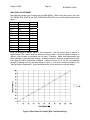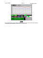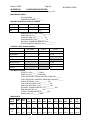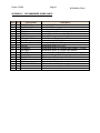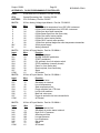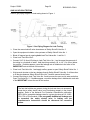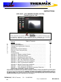
1
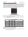
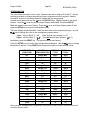
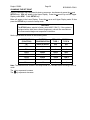
INSTRUCTIONS
BCS 6000C – CSA, BURNER CONTROL SYSTEM
Thermix Project No. 3930
WARNING
These instructions are intended for use only by experienced, qualified combustion startup personnel. Adjustment of this equipment and its components, by unqualified
personnel, can result in fire, explosion, severe personal injury, or even death.
Table of Contents
A.
B.
C.
D.
E.
F.
G.
H.
Subject
General Information …………………………………………………………..
Receiving and Inspection……………………………………………………..
Drawings and Supplemental Literature……………………………………..
Installation……………………………………………………………………...
Adjustments and Final Checkout…………………………….………………
Electronic Valve Characterization……………………………………………
Operation……………………………………………………….………………
Troubleshooting………………………………………………………………..
Appendix A: Operator Interface Screens…………………………………..
Appendix B: Configuration Record………………………….………………
Appendix C: Recommended Spare Parts………………………………….
Appendix D: DL250 Programmable Controller…………….………………
Appendix E: UDC 120L Temperature Instrument…………………………
Appendix F: Exhaust Fan Flow Limit Installation………………………….
Appendix G: Stack Thermocouple Installation…………………………….
Appendix H: Material Thermocouple Installation………………………….
Appendix I: Draft Transmitter Adjustments……………….………………
Appendix J: Flame Supervision and Safety Component Check List…...
Attachments: Applicable Thermix Drawings
Page
2
3
3
3
5
9
10
13
16
20
21
22
24
26
27
28
31
33
These instructions are intended to serve as guidelines covering the installation, operation, and maintenance of Thermix/ Hauck
equipment. While every attempt has been made to ensure completeness, unforeseen or unspecified applications, details, and variations
may preclude covering every possible contingency. WARNING: TO PREVENT THE POSSIBILITY OF SERIOUS BODILY INJURY, DO
NOT USE OR OPERATE ANY EQUIPMENT OR COMPONENT WITH ANY PARTS REMOVED OR ANY PARTS NOT APPROVED BY
THE MANUFACTURER. Should further information be required or desired or should particular problems arise which are not covered
sufficiently for the purchaser’s purpose, contact Thermix Inc. or Hauck Mfg. Co.
THERMIX INC, 7400 St. Francois,
Ph:
514-695-0681
Fax: 514-695-1513
2/04
BCS-6000C-9
Project: R3930
Page 2
BCS6000C-CSA-9
A. GENERAL INFORMATION
The Thermix/Hauck Burner Control System (BCS) provides burner management and
temperature control of a single pilot ignited burner firing on natural gas, oil, or liquid propane
(LP). The spark ignited, gas fired pilot is interrupted after the main burner flame has been
established. Flame supervision is provided by a Honeywell RM7800 series flame relay
combined with an amplifier module and one or two ultra-violet (UV) flame detectors.
A Programmable Logic Controller (PLC) supervises burner operation and provides three
process control loops for material temperature, stack temperature, dryer draft. The PLC is
coupled to a touchscreen display to supply the operator with system status and fault
annunciation.
Two Honeywell UDC120L series instruments are provided for temperature indication and overtemperature protection. The thermocouple of the MATERIAL TEMPERATURE instrument is
positioned to read the temperature of the material as it exits the dryer, while the STACK
TEMPERATURE instrument’s thermocouple senses the temperature of the exhaust gases. The
UDC120L instruments display the process temperature and provide temperature inputs to the
PLC which, in turn, is electronically linked to the burner control motors to automatically adjust
the burner firing rate and maintain process temperature near setpoint. The Operator can assign
control of the burner to either thermocouple.
The alarm contact of the STACK TEMPERATURE instrument is used to shut down the burner if
the preset high temperature limit is exceeded. The PLC also provides high stack and material
temperature alarms, which drive the burner to low fire if their alarm setpoints are exceeded.
Safety Limits are latched with a dedicating latching circuit and pushbutton.
The panel also includes special provisions for adjustable valve characterization which can be
utilized to reduce stack emissions. Refer to Section F, Valve Characterization, for details.
NOTE
High temperature limits will not prevent baghouse fires. They will, when
properly installed and adjusted, shut off the burner when a given
temperature setpoint is exceeded. Outside factors such as chemicals, bag
contamination or other ignition sources are beyond the control of the burner
management system.
CAUTION
The STACK alarm setpoint is factory set at 400°F (240°C). If the system is
equipped with a fabric dust collector (baghouse), consult the manufacturer
for recommended baghouse temperature limitations. Refer to Appendix E
for entering the desired alarm setpoint.
Project: R3930
Page 3
BCS6000C-CSA-9
B. RECEIVING AND INSPECTION
Upon receipt, check each item on the bill of lading and/or invoice to determine that all
equipment has been received. Examine all parts to determine if there has been any damage in
shipment. If equipment is to be stored prior to installation, provide a dry storage area.
IMPORTANT
For optimum use of the BCS panel, it is suggested that the drawings
provided by Thermix/Hauck be referred to for limit switch and valve
installation, and wiring. In the event that a recommended switch or valve is
not used, it may be necessary to connect jumper wire(s) between
appropriate terminals in the control panel or burner junction box. Such
determination remains the responsibility of the Customer, based upon his
application, accepted safe installation and operating procedures, and any
applicable insurance guidelines or governmental regulations.
C. DRAWINGS AND SUPPLEMENTAL LITERATURE
EcoStar IIB
Tabletop Panel Assembly
System Schematic
External Component Wiring
D. INSTALLATION
1.
Locate the tabletop panel on a firm support in an area that is protected from the weather
and free from vibration. The drop-in version is designed to install in an existing
enclosure. Reference drawing 3795 drawings for required cutouts and mounting
dimensions.
IMPORTANT
Operating specifications of 32 to 131°F (0 to 55°C) and 30 to 95% relative
humidity (non-condensing) should be considered in selecting a suitable
location for the control panel.
2.
Provide 120Vac single phase grounded neutral power to the burner control panel. It is
recommended that the customer provide a master disconnect switch to interrupt power
service to the panel. Maintain polarity as indicated on the drawings provided when
connecting the main power source to the panel.
3.
Install a heavy gauge (No. 12 AWG minimum) ground wire between the panel ground
connector and ‘Earth’ ground.
4.
Wire the fuel valves, valve position limit switches and fuel pressure limit switches as
shown on the external component wiring diagram.
Project: R3930
5.
Page 4
BCS6000C-CSA-9
Install the exhaust fan flow limit switch in the dryer exhaust duct as shown in Appendix
F. Wire the normally open contact of the exhaust flow limit to the appropriate terminals
in either the burner junction box or the BCS control panel.
6.
Install the stack temperature thermocouple in the dryer exhaust duct to sense exhaust
gas temperature. See Appendix G. for installation instructions.
7.
Install a Hauck Rapid Response material temperature thermocouple in the material
discharge chute to sense the temperature of the material leaving the dryer. See
Appendix H. for recommended installation.
8.
Connect the thermocouples to the appropriate terminals in the BCS control panel using
thermocouple cable of the same type as the Material and Stack thermocouples.
IMPORTANT
Thermocouple cables must be separated from AC power and control
wiring to avoid interference and nuisance shutdowns. Observe polarity
when making thermocouple connections. Regardless of thermocouple
type, the red wire is always negative.
9.
A pressure tap for the dryer draft transmitter should be located in the 2 or 10 o’clock
position on the dryer breech. Locate the tap midway between the outer edge of the
breeching and the outer edge of the combustion chamber or shell. Cut a hole to
accommodate a 1" (DN 25) pipe coupling angled downward at approximately 30° from
horizontal.
10.
Mount the draft transmitter on a vibration free support, shielded from direct flame
radiation. The operating temperature range is -20 to 180°F (-29 to 82°C). Connect the
transmitter manifold to the LOW pressure tap and leave the HIGH pressure tap open to
atmosphere as a reference. The open tap must be shielded from wind and other
disturbances and should not be in a position where it can collect dirt or water. The
manifold moisture drain should be positioned vertically down.
11.
Install the flame scanner(s) on the burner and wire them to the appropriate terminals in
the burner junction box. Reference burner instructions for scanner installation details.
12.
Refer to the external component wiring diagram for interconnection between the burner
junction box and the BCS panel terminal strips.
IMPORTANT
The flame scanner, draft transmitter, and control motor position feedback
signals should be run in a separate harness from the burner junction box
to the BCS control panel. These cables may be run along with thermocouple
cables but must be separated from all other AC power and control wiring. If
shielded cable is used, only one end of the cable shield should be
grounded. Use one of the ground terminals in the BCS control panel for this
purpose.
13.
Set the purge timer 1TR for the required purge time.
Project: R3930
Page 5
BCS6000C-CSA-9
IMPORTANT
Before igniting the burner, the dryer must be purged to remove possible
accumulation of combustible gases. A minimum of four complete air
changes must be supplied. Multiply the total system volume (dryer, baghouse
and exhaust ducts) in cubic feet (meters) by four. Divide this value by the burner
air capacity in cubic feet (meters) per minute. The result will be the required
purge time in minutes.
14.
Be sure that all equipment and components have been installed in accordance with the
manufacturer’s instructions.
15.
Verify the positions of the FUEL SELECT, AIR SELECT, and AUX SELECT switches on
the printed circuit board. The switches must be set to be compatible with the burner
control motor(s). Select GND for medium torque actuators (Honeywell M6284 or Barber
Colman EA 57). Select 120V for high torque actuators (Barber Colman EA 71 or EA 73)
16.
Verify all wiring and tighten connections.
17.
Clean all traps and filters.
18.
Check all fuel and air supply lines for leaks.
19.
Verify all pressure settings.
IMPORTANT
Periodic testing of the flame supervision components, safety limits and
interlocks should be conducted to insure proper operation. Testing should be
performed by personnel who are familiar with the equipment and the functions
of the various controls. See Appendix J for a checklist and procedure.
E. ADJUSTMENTS & FINAL CHECKOUT:
Record all settings on the Configuration Record Sheet provided in Appendix B.
IMPORTANT
The burner control motors incorporate a position feedback slidewire. A 5 VDC
supply voltage from the panel is connected to the slidewire in order to generate
0 to 5 VDC position feedback signals for the PLC. The following control motor
calibration procedure must be performed before operating the burner for the first
time. Recalibrate annually or whenever a control motor is serviced or
replaced.
The touchscreen provides access to the system operating parameters. Note that touching any
of the numeric displays with white text on a blue background will provide a pop-up keypad for
numeric entry. The use of a pencil eraser, wooden or plastic stylus is recommended for more
precise selection. In order to extend the life of the display, it has been programmed to enter a
screen saver mode five minutes after the burner is stopped. Simply touch the display to deactivate the screen saver.
Project: R3930
Page 6
BCS6000C-CSA-9
MOTOR CALIBRATION & SETUP Screen
Press the MAIN MENU key to access the menu screen, then press the MOTOR CALIBRATION
& SETUP button to display the calibration screen.
MOTOR CALIBRATION
The control motor DEADBAND settings determine the allowable deviation (+/-) of actual
control motor position from setpoint without corrective action by the motor control
outputs (minimum 0.2%, maximum 2.5%, typically set at 0.5% for fuel and 0.8% for air).
These parameters should be set as low as possible without causing the control motors
to ‘hunt’ excessively. Touch the numeric displays and use the popup keypad to enter a
deadband setting for each motor.
Press the ZERO button to drive all control motors closed for calibration and record the
slidewire feedback signals. Confirm that all motors have reached their low fire positions
before beginning span calibration.
Press the SPAN button to drive the motors open and record the resulting feedback
signals. Verify that all motors have fully opened before pressing the OFF button to store
the span values and end motor calibration.
BURNER OPERATING PARAMETERS
Set the BURNER OUTPUT LIMIT at 100.0% for normal operation. This value may need
to be lowered to accommodate system limitations.
Enter a LOW FIRE AIR percentage if applicable. The burner will lightoff with the air
motor at zero and then drive open to the low fire setting to minimize blower surge.
The LIGHTOFF TIME setting determines how long the air and fuel valves will remain in
their lightoff positions before returning to their low fire settings. Timing begins as soon
as the main fuel valve has opened.
If the optional gas flow display and totalizer are installed, set the GAS PRESSURE to
match the pressure, in osig, measured just upstream of the gas orifice flange assembly.
TEMPERATURE DISPLAY
If the Material and Stack temperatures displayed on the touchscreen are significantly
different from the UDC120L instrument displays, a positive or negative BIAS value may
be entered for each instrument.
CONTROL LOOP TUNING Screen
After setting and recording all parameters on the Motor Calibration & Setup screen, press MAIN
MENU key to return to the menu screen then select the CONTROL LOOP TUNING button to
display the loop tuning screen. This screen is used to enter tuning constants for each of the
three PID control loops. MATERIAL or STACK temperature control may also be selected on
this screen. Manual control of the burner firing rate and exhaust damper control motors are also
provided.
Enter a GAIN setting for each loop. Note that Gain = 100/Proportional Band% or
Proportional Band% = 100/Gain. For example, a Gain of 2 is equivalent to a
Proportional Band setting of 50%. Note that the range of the PID control loops in the
BCS6000 is 1000.
Enter a DEADBAND setting (°F for temperature and "WC for draft) for each loop. This
value should be as small as possible without excessive ‘hunting’ by the control
actuators.
Enter a RESET setting for the Material and Stack control loops. Note that Reset is
expressed in minutes per repeat rather than repeats per minute. Therefore, the smaller
the setting the more frequently reset action will be repeated.
Project: R3930
Page 7
BCS6000C-CSA-9
Enter a RATE setting (seconds) if desired for Material and Stack control. Note that Rate
tends to de-stabilize the control and may be left at zero.
Enter CYCLE time settings (seconds) for the Draft control loop. This loop provides
duplex time proportional control outputs for the exhaust damper actuator and has
separate Open and Close cycle times similar to the DPS instrument it replaces.
AUTO TUNE
The Material, Stack and Draft control PID loops are each equipped with an AUTO TUNE button.
Please note the following before initiating the auto tune procedure:
Make a note of the existing tuning parameters on the Control Loop Tuning Screen before
beginning Auto Tune. Factory default settings are given in the Configuration Record
Sheet.
Only one loop at a time may be tuned.
The process should be operating under normal conditions before beginning the Auto
Tune procedure. Do not change material feed rate, mix or setpoint while Auto Tune is in
progress.
Stabilize the temperature or draft as close as possible to the setpoint in MANUAL, then
switch the loop to AUTO and press the AUTO TUNE button to begin.
For the Material and Stack temperature control loops, burner OUTPUT must be less
than 60% for the Auto Tune sequence to be preformed. Auto Tune will increase burner
output by 10% and calculate new gain and reset values based on the process response.
Auto Tune will be complete after the associated temperature has increased by
approximately 40°F (4°C). Consult Hauck’s Service department if a larger or smaller
step is required.
For Draft control, the loop will be cycled between 100% and 0% three times during the
course of the Auto Tune procedure.
Auto Tune may be interrupted, if necessary, by placing the control loop in manual.
The resulting GAIN and RESET parameters (GAIN only for Draft control) will be
automatically updated when the sequence is completed.
For processes with significant dead time (such as a rotary dryer) it may be desirable to
decrease the GAIN parameter.
RUN MENU Screen
After all loop tuning settings have been recorded, return to the MAIN MENU, then press RUN
MENU to display the run menu screen. This screen provides control mode selection, startup
ramp settings for automatic temperature control, low fire drive alarm settings, and draft control
setpoints.
DRAFT CONTROL
Enter a Draft Control PURGE SETPOINT for use during the burner purge sequence.
This value is normally set higher than the normal draft setpoint in order to prevent
dusting as the air damper drives open for purge.
Enter LOW FIRE and HIGH FIRE SETPOINTS for Draft Control. The draft setpoint will
automatically ramp from the low fire to the high fire setpoint as the burner firing rate
increases.
Enter a TRANSFER DELAY time in seconds to set the length of time after burner ignition
is initiated that the purge setpoint remains active for Draft Control before transferring to
the normal operating setpoint.
Project: R3930
Page 8
BCS6000C-CSA-9
To accommodate variations in material moisture or composition and prevent nuisance
shutdowns, provisions are made for automatic draft setpoint increase. The PLC senses
‘puffs’ in the dryer drum and automatically increases dryer draft if a set number of ‘puffs’
occurs within a ten second time window. Set the desired increase via the INCREASE
DRAFT BY _._ _"WC display and enter values in the IF DRAFT DROPS BELOW
_._ _"WC and MORE THAN __ TIMES fields. For example, with settings of 0.02"WC,
0.10"WC and 2 Times, the dryer draft setpoint would be increased by 0.02"WC if dryer
draft dropped below 0.10"WC more than two times within a ten second interval due to
puffing. Note that the Draft Control setpoint returns to its original setting when the
burner is shut off.
TEMPERATURE CONTROL
Select MATERIAL or STACK temperature control.
Set a START AT and RAMP AT percentage for startup. If automatic temperature control
is selected, the burner will drive to the START AT __% setting as soon as the main
flame has been established. The control output will then begin to RAMP AT __% per
minute until the temperature is within 10°F (5.5°C)of setpoint or the output of the
selected control loop is less than or equal to the ramp output. The ramp will then stop
and the control loop will assume control of the burner firing rate.
The burner will be forced to low fire if the stack temperature exceeds the LOW FIRE
DRIVE IF STACK GREATER THAN __ F setting.
Likewise, the burner will be forced to low fire if material temperature exceeds the LOW
FIRE DRIVE IF MATERIAL GREATER THAN __ F setting.
LINKAGE SETUP
After motor calibration is completed and system setup parameters have been set, press the
LINKAGE SETUP button to enter the Linkage Setup mode. The fuel and air control motors will
be released from low fire and respond to the output of the temperature control loop. Return to
the MAIN screen and place the temperature control loop in MANUAL. Drive the motors as
required to adjust fuel and air control valve linkages. Confirm all linkage adjustments and insure
that control arms and linkage rods are tight, then return to the RUN MENU screen and select
either MATERIAL or STACK control to return to normal operation.
Verify that all low fire limit switch contacts are closed, i.e., slot 2, input 5 is ON when the burner
is at 0%, and OFF when the burner leaves low fire. Refer to the burner operating instructions
for switch adjustment.
TRANSMITTER ZERO
Allow the unit to warm up for at least five minutes before adjusting the Transmitter Zero. Use
the shutoff cocks in the transmitter manifold to isolate the transmitter from the dryer, and to
open the LOW pressure tap to atmosphere. The transmitter display and the touchscreen
display of the BCS 6000 should both read 0.00. Reference Appendix I for transmitter
adjustments, if necessary.
TIME AND DATE SETTING
Simultaneously press the upper left and lower left corners of the touchscreen to enter the
screen setup mode then select CLOCK to access the Time and Date Settings. Use the keypad
to enter the desired value, then press Sec, Min, Hr, Day, Mon, or Yr as applicable. For
example, to set the month to September, use the keypad to enter ‘9’, then press ‘Mon’. Use the
EXIT buttons to return to normal operation.
Project: R3930
Page 9
BCS6000C-CSA-9
F. ELECTRONIC VALVE CHARACTERIZATION
WARNING
Adjustment of this equipment by unqualified personnel can result in fire,
explosion, severe personal injury, or even death. This procedure requires the use of
a stack analyzer to properly adjust air/fuel ratio and optimize burner performance. It is
intended for qualified personnel, familiar with combustion systems and the
interpretation of stack emission readings. Electronic Valve Characterization is designed
to provide for minor adjustments to the air control valve position only. The low fire start
positions and overall valve strokes must be set by adjustment of the valve/motor
linkages.
To facilitate burner setup and optimize emissions of the EcoStar IIB burner, the BCS6000
system has been equipped with Electronic Valve Characterization (EVC). This feature provides
for creation of separate motor response curves for the air and fuel control motors. Regardless
of fuel selection, the air control motor directly follows the heat demand output of the temperature
controller. For example, 15% output from the temperature controller will result in the air control
motor driving 15% open. Meanwhile, the fuel control motor will follow a separate curve
established by setting ten characterization (bias) points as shown in Figure 1.
Figure 1. Example of EVC Fuel Bias Settings
Project: R3930
Page 10
BCS6000C-CSA-9
BIAS POINT ADJUSTMENT
Bias adjusting screens are accessed via the MAIN MENU. Before firing the burner, verify the
OIL FIRING BIAS POINTS and GAS FIRING BIAS POINTS are set to the default values listed
below.
Point
Light off
Low Fire
10%
20%
30%
40%
50%
60%
70%
80%
90%
100%
Oil/LP
3.0
0.0
5.0
10.0
15.0
25.0
35.0
45.0
55.0
65.0
77.5
100
Gas
0.0
10.0
15.0
20.0
30.0
40.0
50.0
60.0
70.0
80.0
90.0
100
Setup an analyzer to monitor stack or drum emissions. With the burner firing in manual at
approximately 10% output, select the bias point setting screen. Allow the analyzer readings to
stabilize, then increase or decrease the fuel input, if required. Make small adjustments and
allow readings to settle after each change. Increase the burner firing rate to approximately 20%
and repeat the above adjustment procedure. Continue for the 30, 40, 50, etc or extrapolate
settings by plotting them on the chart shown in Figure 2. Record the resulting settings in the
Table provided in Appendix B. Press the MAIN button to exit and return to normal display.
Figure 2. Blank Chart for Plotting EVC Fuel Bias Settings
Project: R3930
Page 11
BCS6000C-CSA-9
G. PANEL OPERATION
1. Open all manual shutoff valves to supply air and fuel to the pilot and burner systems.
2. Move the panel POWER switch to ON and verify that the FUEL SELECTOR switch is in the
desired position.
a. The temperature instruments, touchscreen display, flame relay and PLC will perform
their self-test procedures.
b. The burner control motors will drive closed.
c. The RESET indicator will come on.
d. A ‘
...’ message will be displayed.
3. Start the exhaust fan, combustion air blower, and all other equipment required for plant
operation. After the exhaust fan limits have closed, the HELD CLOSED indicator of the draft
control will disappear and the exhaust damper will be released to control dryer draft.
4. Select MATERIAL or STACK control and verify the setpoints of both.
5. Press the LIMITS SET push button to latch limits circuit.
6. If all system limits are closed,:
a. ‘PRESS RESET TO START PURGE’ will appear in the message box.
b.
The selected fuel motor will drive to its lightoff position.
7. Momentarily press the LIMITS SET pushbutton to latch limits circuit and initiate the system
purge sequence.
a. An ‘
message will appear as the burner air control motor drives
open.
b. After the air control motor has opened more than 50%, purge timer 1TR will be
energized and begin timing and a ‘
’. message will appear.
c. The fuel control motors will drive to their light off positions.
8. After the purge delay has been completed, 1TR timer will actuate and a ‘ ’
message will appear as the air control motor drives closed to prepare for pilot ignition.
9. When the air and fuel motors have reached their light off positions and all burner low fire
limit switches have closed, the START pushbutton will flash and a ‘’
message will be displayed.
10. Momentarily press the START pushbutton to begin the burner ignition sequence.
a. The flame relay will be energized and a 10 second pilot trial for ignition time will
begin.
b. The ignition transformer and pilot solenoid valves will be energized and an ‘
’ message will appear.
11. If a satisfactory pilot flame is detected by the UV scanner:
a. The START pushbutton will stop flashing and remain on and a message
will be displayed.
b. Flame signal strength (0-5Vdc) will be displayed on the flame meter. Minimum
acceptable signal is 0.5Vdc.
c. Power will be supplied to the main fuel valves.
12. Three seconds after the pilot flame has been detected:
a. The ignition transformer will be de-energized.
Project: R3930
Page 12
BCS6000C-CSA-9
b. A ‘
’ message will appear.
13. As soon as the main fuel valve and valve open input have been powered:
a. Pilot timer 2T will be energized and the ten second main flame trial for ignition time
will begin. The lightoff timer in the PLC will also begin its timed delay.
b. A message will be displayed.
14. After the trial for ignition timer has completed its delay:
a. The pilot solenoid valves will be de-energized and the pilot will go out.
15. After the lightoff timer has completed its delay:
a. The burner control motors will be released to follow the temperature control output.
b. A message will be displayed.
16. Start material flow to the dryer. If the temperature control loop is in AUTO, the burner will
drive to the START AT percentage then begin ramping at the RAMP AT rate set on the RUN
MENU screen. If MANUAL temperature control has been selected, use the INC and DEC
buttons to manually control the burner firing rate or press the OUTPUT display and enter the
desired output value via the popup keypad.
17. Note that the burner may be forced to low fire at any time by pressing the DRIVE TO LOW
FIRE button.
a. The button will be highlighted and will appear in the message
box.
b. Press the button a second time to release the burner from low fire.
18. To terminate burner operation, press the STOP pushbutton.
a. The flame relay and all fuel valves will be de-energized.
b. The air and fuel control motors will drive closed.
c. A ’BURNER STOPPED...’ message will be displayed and the RESET indicator will
come on.
Project: R3930
Page 13
BCS6000C-CSA-9
H. TROUBLESHOOTING
Use the HELP screens on the touch screen or refer to the following table.
MESSAGE
DIAGNOSTICS
The difference between the Zero and Span feedback values of each
motor must be greater than 3300. Verify that the motors travel full
stroke during the motor calibration procedure.
* Indicates that the gas control motor has failed to respond to the
motor positioning output signals of the PLC. Check fuse 5 on the
printed circuit board. Also monitor slot 4 outputs 4 and 5 and relays
R6 and R7.
* Indicates that the air control motor has failed to respond to the
motor positioning output signals of the PLC. Check fuse 45 on the
printed circuit board. Monitor slot 4 outputs 6 and 7 and relays R8
and R9.
* Indicates that the oil or LP control motor has failed to respond to
the motor positioning output signals of the PLC. Check fuse 47 on
the printed circuit board. Monitor slot 5 outputs 6 and 7 and relays
R11 and R12.
* The control algorithm does not normally allow the theoretical fuel
motor position to be greater than the air position. A fuel motor
malfunction may cause this condition to occur.
Monitor slot 2 input 7, terminals 24 thru 24E. This message appears
if the purge air pressure limit, exhaust damper open limit, or any of
the fuel valve proof of closure switches fails to close.
Monitor slot 2 input 5. Verify that all low fire limit switches are closed
(120Vac on terminal 21) when the control motors are in the low fire
start position.
Check the low fire alarm setting on the RUN MENU screen. The
burner will be held at low fire until stack temperature falls below the
alarm setpoint
Check the low fire alarm setting on the RUN MENU screen. The
burner will be held at low fire until material temperature falls below
the alarm setting.
Monitor slot 1 input 6 and the ALARM indicator of the Honeywell
flame relay. This fault normally indicates that the pilot has failed to
ignite within the trial for ignition period. Verify that air, fuel and spark
are being supplied to the pilot. Other possibilities include:
1. Premature flame signal. If the flame meter indicates presence of
a flame before the ignition sequence is started, the flame relay will
lockout and the RESET indicator will come on. Check for fire in the
dryer drum or for a failed UV scanner.
2. Bad or missing ground. The Honeywell flame relay requires a
120Vac grounded neutral power supply for proper operation.
3. Flame amplifier failure. The flame amplifier may need to be
replaced.
* The control motor and excess fuel faults all indicate possible problems with the burner control
motors or the position feedback circuits. Silence the alarm horn and make note of the motor
position values displayed on the MOTOR CALIBRATION screen, then press the ALARM
SILENCE button a second time to reset the fault. Shut off the burner and verify that all control
motors drive to their ZERO and SPAN positions, and that the feedback signals change smoothly
as the motors drive. If not, check fuse 99 and verify that 5Vdc exists between terminals 82 (+)
and 81 (-). Also, check fuses 5, 45 and 47 on the fused terminal blocks.
Project: R3930
Page 14
BCS6000C-CSA-9
MESSAGE
DIAGNOSTICS
Monitor slot 2 input 0. Check the exhaust fan flow switch (power on
terminal 12) and the exhaust fan motor starter interlock (power on
terminal 13).
Monitor slot 3 input 1. Verify that the burner blower is running and
check the secondary air starter interlock (power on terminal 14).
Monitor slot 2 input 1. Verify that the secondary air pressure switch
is made (power on terminal 16). For EcoStar IIB burners, jumper
terminals 14 to 15A in the burner J-Box.
Monitor slot 3 input 4. Verify that the manual gas shutoff valve is
open and that the low gas pressure switch is made (power on
terminal 16A).
Monitor slot 3 input 0 and the high gas pressure switch (power on
terminal 17).
Monitor slot 3 input 5. Verify that the manual shutoff valve is open
and that the low pressure switch is made (power on terminal 17A).
Monitor slot 3 input 2 and the high oil or LP pressure switch (power
on terminal 17B).
Monitor slot 3 input 3. Verify that the primary air interlock and
pressure switch or compressed air pressure switches are made
(power on terminals 17C and 17D
Monitor slot 2 input 2. For heavy oil systems, verify that the oil
heater is operating and the oil temperature switches are made
(power on terminal 18).
Monitor slot 2 input 3. Check for power on terminals 25 and 26.
Observe the display and OUT indicator of the stack temperature
instrument. A full scale reading (842°F or 450°C) indicates an open
TC or broken wire
Indicates that the flame relay has locked out due to a flame failure.
Check burner setup.
Monitor slot 2 input 6. This input must be received within 20
seconds after the pilot flame has been recognized. Verify that
jumper wires are installed on the control panel terminal strip
between terminals 22 and 29 for gas and between terminals 30 and
44 for oil. For some applications it may be necessary to remove
these jumpers and connect the valve open limit switch in the main
fuel valve instead. Consult Hauck’s Service Department for details.
Indicates low touchscreen battery voltage. Replacement batteries
are available from Automation Direct (Part No. EZ-BAT). Consult
the EZTouch Hardware User Manual for battery replacement
instructions.
Indicates low PLC battery voltage. The battery compartment is
located in the CPU. A replacement battery is available from Hauck
(Part No. 62311) or Automation Direct (Part No. D2-BAT-1).
Project: R3930
Page 15
BCS6000C-CSA-9
ALARM HISTORY Screen
An alarm history screen is also provided for use as a troubleshooting guide. From the MAIN
MENU screen press ALARM HISTORY to view a list of the last 99 logged events and the order
in which they occurred. Page up or down, if necessary, to view the entire list. Use the LINE UP
or LINE DOWN button to select a particular item then press DETAILS to view the time and date
information. Note that ‘FLAME ON’ and ‘BURNER STOPPED’ are included in the alarm list for
monitoring purposes even though they are not alarm conditions.
The ALARM COUNT screen shows how many times each alarm has occurred.
MANUAL BYPASS
In the event of a touchscreen display failure, the burner firing rate may be adjusted manually by
the following procedure.
Press the LIMITS SET & RESET button to initiate system purge. Wait for the START
indicator to begin flashing, then press START to ignite the burner.
As soon as the burner has ignited, press and hold both the START and ALARM SILENCE
pushbuttons for two seconds to enter the manual bypass mode. The alarm horn will chirp to
indicate that the manual bypass mode has been activated.
Using the readouts of the MATERIAL and STACK temperature instruments, the burner firing
rate may be manually adjusted by pressing the START button to increase, or the ALARM
SILENCE button to decrease. Each chirp of the alarm horn indicates a 1% output change.
Momentarily press the STOP pushbutton to shut off the burner and exit the manual bypass
mode.
Project: R3930
Page 16
BCS6000C-CSA-9
APPENDIX A: OPERATOR INTERFACE SCREENS
MAIN SCREEN
This screen displays overall system status and is the default screen on system power-up. It
provides AUTO/MANUAL control selection and setpoint inputs for the temperature control loops.
Note that the message box in the lower left corner of the screen appears on all screens to
provide the operator with system status messages. The MAIN MENU and RUN MENU buttons
provide quick access to other screens. Indicators below the MATERIAL and STACK
temperature readouts indicate which thermocouple is being used for control.
MAIN MENU SCREEN
Used to access other screens. Also provides language selection and accumulated and
resettable (daily) firing times. If the system is equipped with the fuel flow option, totalized fuel
usage is also displayed. Record the PLC and screen program numbers that appear on this
screen as they will be required if service is requested.
Project: R3930
Page 17
BCS6000C-CSA-9
MOTOR CALIBRATION & SETUP
Reference Section E. Used to ZERO and SPAN the burner control motors and to enter motor
deadband settings. Also provides numeric inputs for burner firing rate limits, gas pressure
correction, and temperature bias settings.
CONTROL LOOP TUNING
Reference Section E. Used to set PID control loop tuning constants for the Material and Stack
temperature control and Dryer Draft control. Also provides temperature setpoint inputs,
AUTO/MANUAL selection, and AUTO TUNE selection.
Project: R3930
Page 18
BCS6000C-CSA-9
RUN MENU
Reference Section E. Used to set the burner startup percentage and ramp rate for automatic
temperature control. Also provides for low fire drive alarms and draft setpoint inputs, selection
of control mode and parameters for automatic draft increase control.
BIAS POINT SETTINGS
Reference Section F. Two separate screens (GAS and OIL/LP) are provided to setup the
electronic valve characterization for the fuel valve. It provides inputs for fuel valve position for
lightoff and eleven air valve positions (Low Fire, 10, 20, 30… thru 100%). It also displays
pertinent data to aid in burner setup.
Project: R3930
Page 19
BCS6000C-CSA-9
TRENDS
Four separate trend screens provide 5 minute, 15 minute, 4 hour and 8 hour trends of Material
temperature; Stack temperature, Setpoint and burner firing rate.
Project: R3930
Page 20
BCS6000C-CSA-9
APPENDIX B:
CONFIGURATION RECORD
Factory set default values are shown in parenthesis, e.g. (1.0)
MAIN MENU SCREEN
PLC PROGRAM: __________
SCREEN PROGRAM: __________
MOTOR CALIBRATION & SETUP SCREEN
MOTOR
ZERO
SPAN
DEADBAND
FUEL
(0.5)
AIR
(0.5)
BURNER OUTPUT LIMIT: (100.0)__________
LOW FIRE AIR: (0.0) __________ %.
LIGHTOFF TIME: (10) __________ sec
GAS PRESSURE: (24.0) __________ oz.
MATERIAL TEMPERATURE BIAS: (32.0) __________
STACK TEMPERATURE BIAS: (32.0) __________
CONTROL LOOP TUNING SCREEN
MATERIAL
STACK
DRAFT
GAIN
(2.00)
(2.00)
(1.25)
DEADBAND
(1)
(1)
(0.10)
RESET
(1.00)
(1.00)
RATE
OPEN CYCLE
(1.00)
CLOSE CYCLE
(1.00)
FILTER
(1)
RUN MENU SCREEN
START AT (30.0) ______ % THEN
RAMP AT (50.0) ______ % PER MIN
LOW FIRE DRIVE IF STACK GREATER THAN (380) ______
LOW FIRE DRIVE IF MATERIAL GREATER THAN (400) ______
PURGE SETPOINT: (0.50) __________ "WC
LOW FIRE SETPOINT: (0.25) __________ "WC
HIGH FIRE SETPOINT: (0.35) __________ "WC
SETPOINT TRANSFER DELAY: (1.0) __________ SEC
REDUCE DRAFTBY (0) ______ "WC
IF DRAFT DROPS BELOW (0) ______ "WC
MORE THAN (10) ______ TIMES
BIAS POINTS
Firing
Mode
Light
Off
Low
Fire
1
10%
2
20%
3
30%
4
40%
5
50%
6
60%
7
70%
8
80%
9
9%
10
100%
(5.0)
(5.0)
(10.0)
(20.0)
(30.0)
(40.0)
(50.0)
(60.0)
(70.0)
(80.0)
(90.0)
(100.0)
(3.0)
(0)
(5.0)
(10.0)
(15.0)
(25.0)
(35.0)
(45.0)
(55.0)
(65.0)
(77.0)
(100.0)
Gas
Oil or
LP
Project: R3930
Page 21
BCS6000C-CSA-9
APPENDIX C: RECOMMENDED SPARE PARTS
Item Qty
1
2
3
4
5
6
7
8
9
10
11
12
13
14
15
16
17
18
19
20
2
1
1
1
1
1
2
1
1
1
1
1
1
1
1
1
1
1
Part Number
C7027A1049
RM7890A1015
R7849A1015
TC100AJ
TC200AJ
H3CR-A8
RMI-A 4 5 120vac
DG10T
DC120L-1-7-0-0-1-000
D2-250
F2-08AD-2
D2-08NA-1
D2-08TR
F2-08AD-1
EZ-S10C-F
SC110
46311
PS120AC/24DC/2.5
Description
Honeywell, UV flame detectors
Honeywell, Flame programmer
Honeywell, UV amplifier
Hauck, Material thermocouple type J
Hauck, Exhaust thermocouple type J
Omron, Timer
Carlo Gavazzi, Relay, 2 pole 120vac
Kromschroder, Airflow switch
Honeywell, High Limit & Temperature controller
Automation Direct, PLC CPU
Automation Direct, PLC analog input module – 0-10vdc
Automation Direct, PLC digital input module
Automation Direct, PLC digital output module
Automation Direct, PLC analog input module – 4-20mA
EZautomation, Touch screen
Mallory, Sonalert, Alarm horn
Crydom, Solid State relays
Phoenix, 24vdc-2.5A power supply
Project: R3930
Page 22
BCS6000C-CSA-9
APPENDIX D: DL250 PROGRAMMABLE CONTROLLER
BASE:
9-Slot Base w/8 I/O Modules. Part No. D2-09B
CPU:
BATTERY:
Central Processing Unit. Part No. D2-250
CPU 3V Battery. Part No. D2-BAT
SLOT 0:
8-Point Analog Voltage Input Module. Part No. F2-08AD-2
Input
1
2
3
4
5
6
7
8
24V
0V
Wire
92
93
94
91
83
85
84
88
99
81
SLOT 1:
8-Point AC Input Module. Part No. D2-08NA-1
Input
X20
X21
X22
X23
X24
X25
X26
X27
COM
Wire
28
23
38
60
36
56
58
48
L2
SLOT 2:
8-Point AC Input Module. Part No. D2-08NA-1
Input
X30
X31
X32
X33
X34
X35
X36
X37
COM
Wire
13
16
18
26
54
21
43
24
L2
SLOT 3:
8-Point AC Input Module. Part No. D2-08NA-1
Input
X40
X41
X42
X43
X44
X45
X46
X47
COM
Wire
17
14
17B
17D
16A
17A
75
76
L2
Function
0-5Vdc Material temperature from UDC120L instrument
0-5Vdc Stack temperature from UDC120L instrument
1-5Vdc from dryer draft transmitter
0-5Vdc flame signal from the flame relay
0-5Vdc Gas control motor position
0-5Vdc Air control motor position
0-5Vdc Oil/LP control motor position
1-5Vdc from optional baghouse outlet temperature transmitter
24Vdc power supply
Analog reference
Function
RESET pushbutton
ALARM SILENCE pushbutton
START pushbutton
OIL selected, from fuel selector switch
STOP pushbutton (normally closed)
Flame on, from flame relay
Reset required, from flame relay
Spare
AC Neutral
Function
Exhaust fan limits
Secondary air interlock
Low oil temperature
Stack temperature limit
Purge complete from 1TR timer
Low fire limit switches
Main fuel valve open
Purge air and main fuel valve closed limits
AC Neutral
Function
High gas pressure limit
Secondary air motor starter interlock
High Oil or LP pressure
Atomizing air limits
Low gas pressure
Low oil pressure
Opt switch
Spare
AC Neutral
Project: R3930
Page 23
BCS6000C-CSA-9
SLOT 4:
8-Point Relay Output Module. Part No. D2-08TR
Output
Y0
Y1
Y2
Y3
Y4
Y5
Y6
Y7
Wire
63
64
65
66
67
68
69
70
SLOT 5:
8-Point Relay Output Module. Part No. D2-08TR
Output
Y10
Y11
Y12
Y13
Y14
Y15
Y16
Y17
Wire
49
20
71
27
40
42
72
73
SLOT 6:
8-Point Relay Output Module. Part No. D2-08TR
Input
Y20
Y21
Y22
Y23
Y24
Y25
Y26
Y27
Wire
200
201
202
203
204
205
206
207
SLOT 7:
8-Point Analog Input Module. Part No. F2-08AD-1
Input
Yxx
Yxx
Yxx
Yxx
Yxx
Yxx
Yxx
Yxx
Wire
96
97
95
98
101
102
103
104
Function
Purge relay, R2
Run relay, R3
Pilot scanner relay, R4
Pilot relay, R5
Gas motor increase relay, R6
Gas motor decrease relay, R7
Air motor increase relay, R8
Air motor decrease relay, R9
Function
Alarm horn
START indicator
Spare relay, R10
RESET indicator
Draft increase relay, R13
Draft decrease relay, R14
Oil/LP motor increase relay, R11
Oil/LP motor decrease relay, R12
Function
Limits Set PB
Spare
Spare
Spare
Spare
Spare
Spare
Spare
Function
Spare
Spare
Spare
Spare
Spare
Spare
Spare
Spare
Project: R3930
Page 24
BCS6000C-CSA-9
APPENDIX E: UDC120L SERIES LIMIT INSTRUMENTS
Two Honeywell UDC120L series instruments (Part No. 300003 ) are provided for temperature
indication and over-temperature protection. Each instrument receives a thermocouple input and
provides a 0 to 5Vdc temperature signal to the PLC. The thermocouple of the MATERIAL
CONTROL instrument is positioned to read the temperature of the material as it exits the dryer
while the STACK TEMPERATURE instrument’s thermocouple senses the temperature of the
exhaust gases. The alarm contact of the STACK TEMPERATURE instrument is used to shut
down the burner if the preset high temperature limit is exceeded.
UDC 120L Instrument Front Face Display
Upper Display: Normally displays process temperature. Also displays parameter values or
selections when in the set up mode.
Lower Display: Shows value of set point. Also displays function groups and parameters when
in the set up mode.
Parameter
Over Range
Under Range
Sensor Break
Option 1 Error
Option 2 Error
Option 3 Error
Option A Error
Error / Fault Indications
Upper
Lower
Description
Display
Display
[HH]
Normal
Input > 5% over-range
[LL]
Normal
Input > 5% under-range
OPEN
Normal
Break in input sensor or wiring
ERR
OPn1
Option 1 module fault
ERR
OPn2
Option 2 module fault
ERR
OPn3
Option 3 module fault
ERR
OPnA
Auxiliary Option module fault
: Used to decrease the setpoint or configuration values.
: Used to increase the setpoint or configuration values.
SET UP: Used in conjunction with the key to enter the set up and configuration modes.
used to advance through the parameters.
Also
Project: R3930
Page 25
BCS6000C-CSA-9
CONFIGURATION
The instruments are factory set for a type J thermocouple with a range of 32 to 842°F Use the
following procedure to change thermocouple type or temperature units if required. Detailed
information is given in the vendor literature supplied with the control panel.
Simultaneously press and hold the
arrow and SETUP Keys. OPtr will appear in the Upper
arrow key until the Upper Display reads ConF, then press SETUP.
Display. Press the
arrow until Upper Display reads 20 then
ULoc will appear in the Lower Display. Press the
press the SETUP key to enter the configuration mode.
The lower display should read InPt. Check the sales order for the thermocouple type: Use the
/ keys to change the value to the corresponding reading below.
J type: -199.9 to 999.9 °F = J.F
K type: -199.9 to 999.9 °F =
(Note decimal point between J & F.)
F
(Note NO decimal point between
& F.)
Momentarily press the RESET key. The symbols should stop flashing.
Press the SETUP key to view the other configuration parameters. Use the / keys to change
parameters if required. Press RESET after changes are made to accept the new values.
LOWER DISPLAY
(FUNCTION)
FACTORY
CONFIGURATION
DEFAULT
TYPE J
OPTIONAL
TYPE K
ruL
Range Max
999.9
2503
rLL
Range Low
-199.9
-400.0
OFFS
0.0
0.0
0.0
CtrL
Hi
Hi
Hi
SPuL
Range Max
999.9
2503
SPLL
Range Low
-199.9
-400.0
ALA1
P_Hi
P_Hi
P_Hi
PhA1
Range Max
999.9
2503
AHY1
0.1
0.1
0.1
ALA2
P-Lo
P_Lo
P_Lo
PLA2
Range Low
-199.9
-400.0
AHY2
0.1
0.1
0.1
USE2
A1_d
A1_d
A1_d
retP
USE3
USE3
USE3
tyP3
0_10
0_5
0_5
ro3H
Range Max
842.0
1399
ro3L
Range Min
32.0
32.0
diSP
EnAb
EnAb
EnAb
CLoc
20
20
20
After your have completed the Configuration cycle power to reset or wait 2 minutes for the unit
to reset to the run mode.
Project: R3930
Page 26
BCS6000C-CSA-9
CHANGING THE SET POINT
and
After the instrument has completed its boot-up sequence, simultaneously press the
SETUP keys. OPtr will appear in the Upper Display. Press the
arrow key until the Upper
Display reads SEtP. Press SETUP key.
ULoc will appear in the Lower Display. Press the
press the SETUP key to enter the setup mode.
arrow until Upper Display reads 10 then
CAUTION
The STACK alarm setpoint is factory set at 400°F (204°C). If the system is
equipped with a fabric dust collector (baghouse), consult the manufacturer
for recommended baghouse temperature limitations.
Set the parameters as shown in the following table.
LOWER DISPLAY
(FUNCTION)
FACTORY
CONFIGURATION
DEFAULT
TYPE J
OPTIONAL
TYPE K
SP
R/min to R/max
400
400
HYSt
0.1
0.1
0.1
FiLt
2
2
2
PhA1
R/max
999.9
2503
AHY1
0.1
0.1
0.1
PLA2
R/min
-199.9
-400.0
AHY2
0.1
0.1
0.1
SLoc
10
0
0
Note: The instrument will remain in the setup mode for 2 minutes before returning to the run
mode.
The
The
key represents increase
key represents decrease
Project: R3930
Page 28
BCS6000C-CSA-9
APPENDIX G: STACK THERMOCOUPLE INSTALLATION
Install a Hauck stack temperature thermocouple in the dryer exhaust duct to sense exhaust gas
temperatures as shown in Figure 1.
Figure 1. Installation of Thermocouple in Exhaust Duct
NOTE
Thermocouple cables must be separated from AC power and control
wiring to avoid interference and nuisance shutdowns. Observe polarity
when making thermocouple connections. Regardless of thermocouple
type, the red wire is always negative.
Project: R3930
Page 29
BCS6000C-CSA-9
APPENDIX H: MATERIAL THERMOCOUPLE INSTALLATION
Install a Hauck Rapid Response Material Temperature Thermocouple in the material discharge
chute to sense the temperature of the material leaving the dryer as shown Figure 1. Wire the
thermocouple to the proper terminals in the panel.
Figure 1. Installation of Thermocouple and “Dam” Dryer Discharge Chute
IMPORTANT
A small clearance of 1" (25mm) maximum should be provided under the
thermocouple so material will not be trapped between the thermocouple and the
chute. Trapped material will cause a heat loss path and the thermocouple will give
erroneous readings.
The thermocouple should make good contact with the material but not be subject to
severe abrasion caused by high velocities. If the material is moving so fast that it
bounces and leaves air adjacent to the thermocouple, the temperature it senses will
be lower than the material. It may be necessary to place a dam in the chute so that
the thermocouple is in a relatively slow moving area next to the dam. The dam must
only be wide enough and high enough to create a localized area of build-up where
the material loses velocity but does not stop flowing. The thermocouple must not
be located in a stagnant zone or erroneous temperature reading will result. Because
of the large number of variables involved, it is impossible to set down any exact size
or location of the dam that will always work. Field experimentation will be necessary if
good results are to be obtained. It is advisable to tack weld the dam in place so that it
can be easily modified if it fails to perform satisfactorily.
Project: R3930
Page 30
BCS6000C-CSA-9
NOTE
During normal operation, the thermocouple should be rotated once a month
to expose a different area of its surface to the abrasive forces of the
material. This procedure will increase the effective life of the thermocouple.
If excessive wear occurs, a protective tube may be added to shield the shaft
in the region of the high velocity flow.
NOTE
Thermocouple cables must be separated from AC power and control wiring
to avoid interference and nuisance shutdowns. Observe polarity when
making thermocouple connections. Regardless of thermocouple type, the
red wire is always negative.
WARNING
This equipment is potentially dangerous with the possibility of serious personal injury and
property damage. Thermix Inc. & Hauck Manufacturing Company recommends periodic
testing of the flame supervisory and safety component equipment in adherence to
Canadian Standards Association (CSA), National Fire Protection Association (NFPA)
standards and insurance underwriter’s requirements. Testing should be performed by
qualified personnel familiar with the equipment and functions of the various safety limits
and interlocks.
Project: R3930
Page 31
BCS6000C-CSA-9
APPENDIX I: DRAFT TRANSMITTER ADJUSTMENTS
The NEXT and ENTER buttons located below the LCD display may be used to adjust or
reconfigure the draft transmitter if required. Wait one or two seconds between each button
press to allow the display to update.
ZEROING
Allow the unit to warm up for at least five minutes before adjusting the transmitter zero. Refer to
Figure 1 and use the shutoff cocks in the transmitter manifold to isolate the transmitter from the
dryer and to open the LOW pressure tap to atmosphere.
Figure 1. Transmitter and Manifold Layout
If the transmitter display does not read 0.00 IN H2O use the following procedure to zero the
transmitter.
Press the NEXT button one time to change the lower display to CALIB.
Press ENTER to change the lower display to CAL AT0.
Press ENTER and the lower display will read AT0 DONE.
Press NEXT to step through the remaining calibration options until the lower display
reads SAVE.
Press ENTER to save the new zero calibration and exit the calibration mode. Note that
calibration changes can be discarded by pressing ENTER when the lower display reads
CANCEL instead of SAVE.
Project: R3930
Page 32
BCS6000C-CSA-9
4 MA ADJUSTMENT
Verify that when the transmitter reads 0.00, the BCS 6000 touchscreen display also reads 0.00.
If necessary, adjust the transmitter 4 mA value using the following procedure.
Press the NEXT button one time to change the lower display to CALIB.
Press ENTER to change the lower display to CAL AT0.
Press NEXT until the lower display reads ADJ 4MA.
Press ENTER and the lower display will read A 4MA .
If the DPS display reads less than 0.00, increase the 4 mA calibrations as follows:
Press NEXT to change the lower display to A 4MA .
Each press of the ENTER button will slightly increase the transmitter output and
the DPS display should increase until it reads 0.00.
If the DPS display reads greater than 0.00, decrease the 4 mA calibrations as follows:
Press NEXT to change the lower display to A 4MA .
Each press of the ENTER button will now slightly decrease the transmitter output
and the DPS display should decrease until it reads 0.00.
Press NEXT to step through the remaining calibration options until the lower display
reads SAVE.
Press ENTER to save the new zero calibration and exit the calibration mode. Note that
calibration changes can be discarded by pressing ENTER when the lower display reads
CANCEL instead of SAVE.
CONFIGURATION PARAMETERS
The transmitter has been factory configured and should not require any field modifications. The
following parameter settings are provided for reference only.
PARAMETER
LOWER DISPLAY
UPPER DISPLAY
External Zero (Not applicable)
EX ZERO
EXZ DIS
Output Direction
OUT DIR
FORWARD
Output Mode
OUTMODE
LINEAR
Output Failsafe
OUTFAIL
FAIL LO
Signal Dampening
DAMPING
NO DAMP
Display Engineering Units
DISP EGU
USE EGU
Select Engineering Units
EGU SEL
INH2O
Lower Range Value
EGU LRV
00.00
Upper Range Value
EGU URV
1.00, 3.00 or 5.00
Project: R3930
Page 33
BCS6000C-CSA-9
APPENDIX J: FLAME SUPERVISION & SAFETY COMPONENT CHECK LIST
Equipment:
Multi-meter capable of measuring Continuity and AC voltage (120Vac)
System Schematic Y7552
CAUTION
The BCS 6000 control panel power must be on to perform the following
checks. Avoid contacting exposed wiring and terminals when checking
voltage or continuity and after removing the pressure switch covers to
make adjustments. Replace all covers as soon as testing is completed.
Start all equipment required for burner operation except the exhaust fan. Verify that
120Vac is not present between the following control panel terminals with the FUEL
SELECTOR switch in the OIL, GAS, and OPT positions.
12 and L2
17A and L2
13 and L2
17B and L2
15 and L2
17D and L2
14 and L2
17C and L2
16 and L2
18 and L2
16A and L2
25 and L2
17 and L2
26 and L2
SECONDARY AIR LIMITS: LOW PRESSURE SWITCH & MOTOR STARTER INTERLOCK
Note: A jumper wire must be installed in the burner junction box between terminals 14 and 15A.
Leave the exhaust fan off and start the combustion air (burner) blower.
Set the multi-meter to read continuity and verify that continuity exist between the following
control panel terminals 14 and16.
Shut off the combustion air blower. Continuity should disappear between terminals 13 and
14 immediately, but should remain between terminals 14 and 16 for several seconds as the
secondary air blower coasts to a stop.
ATOMIZING AIR LIMITS (EcoStar IIB with primary air blower for Oil or LP fired systems
only)
Start the primary air blower only.
Set the multi-meter to read continuity and verify that continuity exist between the following
control panel terminals:
17B and 17C
17C and 17D
Shut off the primary air blower. Continuity should disappear between terminals 17B and
17C immediately, but should remain between terminals 17C and 17D for several seconds as
the primary air blower coasts to a stop.
ATOMIZING AIR PRESSURE (EcoStar IIB with compressed air atomization for Oil or LP
fired systems only)
Shut off the exhaust fan and combustion air blower.
Set the multi-meter to read continuity and verify that continuity exist between the following
control panel terminals:
17B and 17C
17C and 17D
Project: R3930
Page 34
BCS6000C-CSA-9
Shut off the manual valve on the compressed air supply line then carefully loosen the pipe
plug downstream of the compressed air flow meter to bleed off any residual air pressure.
Verify that continuity does not exist between the following control panel terminals:
17B and 17C
17C and 17D
Re-tighten the pipe plug and open the manual valve on the compressed air supply line.
EXHAUST FAN LIMITS: FLOW SWITCH & MOTOR STARTER INTERLOCK
Start the exhaust fan only. Set the multi-meter for AC voltage and verify that 120Vac is
present between the following control panel terminals:
12 and L2
13 and L2
Shut off the exhaust fan. 120Vac should disappear from terminal 13 immediately, but
should remain on terminal 12 for several seconds as the exhaust fan coasts to a stop.
LOW GAS PRESSURE (Gas-fired systems only)
Move the FUEL SELECTOR switch to the GAS position and place the temperature control
loop in manual at 0% output.
Start all equipment required for burner operation, and then momentarily press the RESET
button on the control panel. After the purge sequence is completed press START to
establish the pilot and low fire gas flame.
Close the manual valve in the main gas line to shut off the gas supply. The burner should
shut off, the alarm will sound, and a ‘
message should appear.
HIGH GAS PRESSURE (Gas-fired systems only)
Remove the cover of the high gas pressure switch, make note of the switch setting, then
lower the setting to its minimum value.
Open the manual valve in the main gas line and attempt to restart the burner.
As soon as the main gas valves open, the high gas pressure switch should trip. The burner
will shut off and a message will appear
Return the high gas pressure switch to its original setting and replace the switch cover.
LOW OIL or LP PRESSURE (Oil or LP fired systems only)
Move the FUEL SELECTOR switch to the OIL position. Shut off the oil or LP supply pump
and attempt to start the burner.
The alarm should sound and a message will appear.
HIGH OIL or LP PRESSURE (Oil or LP fired systems only)
Remove the cover of the oil or LP pressure switch. Make note of the high pressure switch
setting, then lower the setting so that it is less than the normal operating pressure.
Start the oil or LP supply pump and attempt to start the burner.
The high pressure switch should trip, the alarm will sound, and a message will appear.
Return the pressure switch to its original setting and replace the switch cover.
Project: R3930
Page 35
BCS6000C-CSA-9
LOW and HIGH OIL TEMPERATURE (Heavy Oil fired systems only)
Shut off the exhaust fan and combustion air (burner) blower.
Set the multi-meter to read continuity and verify that continuity exist between control panel
terminals 17D and 18.
Make note of the low oil temperature switch setpoint, then raise the setting above the
current oil temperature and verify that continuity is lost between terminals 17D and 18.
Return the switch to its original setting and verify that continuity is re-established.
Make note of the high oil temperature switch setpoint, then lower the setting below the
current oil temperature and verify that continuity is lost between terminals 17D and 18.
Return the switch to its original setting and verify that continuity is re-established.
HIGH STACK TEMPERATURE LIMIT
With all limits closed press the RESET button to initiate the system purge sequence.
Press the SET UP and keys simultaneously on the STACK TEMPERATURE instrument.
0 will appear in the upper display and ULoc will appear in the lower display.
Press SET UP key one time to display SP in the lower display and the current setpoint value
in the upper display.
Use the key to lower the setpoint until the limit opens and the OUT and EXCEED
indicators come on.
The alarm will sound and a message will appear.
Acknowledge the alarm and return the STACK TEMPERATURE limit setting to its original
value, then press the RESET key on the STACK instrument to reset the fault and extinguish
the OUT indicator.
FLAME FAILURE TEST
Start the burner and establish the low fire burner flame.
For gas fired systems, simulate flame failure by closing the manual shutoff valve
downstream of the safety shutoff valves, or as an alternative to closing the manual valve on
a gas-fired system, temporarily disconnect field wire 87 from the control panel terminal strip.
After approximately three seconds the Honeywell flame relay will lockout and its red ALARM
indicator will be illuminated. The burner will shut off, the alarm will sound, and a message will be displayed.
Silence the alarm and replace wire 87, or open the manual shutoff valve to resume normal
operation.
Project: R3930
Page 36
BCS6000C-CSA-9
GAS VALVE LEAK TESTING
Refer to gas piping diagram for leak testing shown in Figure 1.
Figure 1. Gas Piping Diagram for Leak Testing
Close the manual shutoff valve downstream of Safety Shutoff Valve No. 2.
Open the equipment isolation valve upstream of Safety Shutoff Valve No. 1.
Bleed off trapped gas by opening both Leak Test Valves No. 1 and No. 2.
Close Leak Test Valve No 2.
Connect 3/16" (4.8mm) ID tubing to Leak Test Valve No. 1 and immerse the open end of
the tubing in a container of water. Hold the tubing vertically 1/8 to 1/4" (3 to 6 mm) below
the surface. If bubbles appear, record the leakage rate in bubbles/min and refer to the
IMPORTANT note at the end of this section.
Close Leak Test Valve No. 1 and apply auxiliary power to open Safety Shutoff Valve No. 1.
Wait several minutes so that any leakage through Safety Shutoff Valve No. 2 will have time
to fill the pipe between Safety Shutoff Valve No. 2 and the manual shutoff valve.
Connect the tubing to Leak Test Valve No. 2 and immerse the open end in water as before.
Open Test Valve No. 2. If bubbles appear, record the leakage rate in bubbles/min and refer
to the IMPORTANT note at the end of this section.
IMPORTANT
The fact that bubbles are present during the leak test does not necessarily
mean that a safety shutoff valve is not functioning properly in the closed
position. Refer to the National Fire Protection Association’s publication
NFPA 86 for acceptable leakage rates for a given pipe size per UL, ANSI,
CSA, FM or EN standards. If the acceptable bubbles/min leakage rate
is exceeded, the safety shutoff valve is leaking and the
manufacturer’s instructions should be referenced for corrective
action.
Project: R3930
Page 37
BCS6000C-CSA-9
WARRANTY
Thermix Combustion Systems Inc. (hereinafter called “seller”) warrants and guarantees to
the original buyer that all equipment and parts manufactured by the seller are free from defects
in material and workmanship. Any pieces of equipment failing in normal service within a
reasonable period of time, not exceeding sixteen (16) months from the date of shipment or
twelve (12) months from the date of commissioning, with the exception of refractory materials,
will be promptly replaced without cost to the original buyer when returned to the factory of the
seller.
If any product is found unsatisfactory under this warranty, the buyer should notify the seller in
writing and after receipt of shipping advice and return authorization, buyer may return it directly
to Thermix Combustion Systems Inc., 7400 Chemin St. Francois, St. Laurent, QC, CANADA
carrying charges prepaid. Such equipment will be replaced or put in proper operating condition,
free of all charges except transportation, and the correction of any defects by repair or
replacement by the seller shall constitute of all obligations and liability of the seller to the buyer
under this Warranty and the Contract of Sale.
The seller is not responsible for damage to its products through improper installation,
maintenance, use or attempts to operate it above its rated capacity, intentionally or otherwise, or
for unauthorized repairs. Any failure to notify the seller of unsatisfactory operation, or any
improper or unauthorized installation, maintenance, use, repairs or adjustments, shall terminate
this warranty and shall relieve seller from any future responsibility there under.
Seller shall not be liable for special or consequential damages in any claim, action, suit or
proceeding arising under this Warranty or the Contract of Sale, nor shall there by any liability
there under for claims of labor, loss of profits or good will, repairs or other expenses incidental
to replacement.
This Warranty is given in lieu of all other warranties and guarantees of any kind which, except
the implied Warranty of title, are expressly negative, whether the same be implied, created by
statute or otherwise.
Thermix Combustion Systems Inc.
7400 Chemin St. François
Ville St. Laurent, Québec
H9X 1T5, Canada
Ph :(514) 695-0681
Fx :(514) 695-1513
www.thermix.com