1
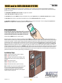
DoorKing Part Number
VOICE and/or DATA CELLULAR SYSTEM
1800-080
The Voice/Data or Data Only Cellular System operates on DoorKing’s cellular network that is hosted on the AT&T 4G LTE network where
available. The system provides voice communication, data communication, or both, depending on the registration plan selected on DoorKing’s
Cellular Server website.
The VOICE/DATA or DATA ONLY Cellular System is designed to be used with:
- 1833, 1834, 1835, 1837, and 1838 entry systems.
The Voice/Data cellular system MUST be wired to the telephone entry system’s phone line (voice) and RS 232 connection (data). See page 2.
The Data Only cellular system is only wired to the telephone entry system’s RS 232 connection (data). See page 2.
The Voice/Data or Data Only cellular system will work with TWO 1830 entry systems connected to it. These are designated as System A and
System B. See next page to wire 2 1830 entry systems to the cellular system.
&T
AT work
t
ne
Prior to Installation:
l
na
Sigength
Str
An existing AT&T operated cellular phone will be needed to
test the signal strength of the AT&T cellular network in the
desired installation location (a smart phone is preferred).
Analog modems DO NOT work on a cellular network.
Before the cellular system can be installed, the installation location MUST have good cellular signal strength for reliable communication. This
location needs to be tested using an existing active AT&T cellular network phone. Activate the phone near the position where you want the plastic
enclosure to be installed. 3-4 bars of signal strength should be indicated on the phone for a reliable signal. If 3-4 bars are not achievable in that
specific location, then try moving the phone around and see if at least 3-4 bars can be achieved and maintained in a nearby location. If a smart
phone is being used, try using the browser to connect to a website to verify good data transfer. DO NOT install the enclosure in a WEAK or NO
signal area. Generally, the higher the enclosure is mounted, the better the reception. This also helps protect against vandalism. The enclosure
should be located to minimize the wire runs to “SYSTEM A” 1830 telephone entry system. Keep the wire run between the two devices as short as
possible, maximum 100 feet. This allows less chance for lightning surges or other electrical interference to disrupt the cellular signal. Keep the
enclosure away from any metal. This can also disrupt the signal. After the 3-4 bar signal strength has been confirmed (and the smart phone has
good browser data transfer if used for signal testing), the installation can begin.
lar
llu
e
C tem
s
Sy
Installation Steps:
Page 2: 1. Install and wire cellular system to 1830(s).
Page 3: 2. Power up cellular system.
Page 3: 3. Register cellular system (and 1830(s)) online,
this can be done before or after cellular system has been
installed.
Page 3: 4. Test cellular system.
Page 4: 5. Program cellular system.
A
M
E
ST
Page 5: 6. Troubleshoot cellular system if necessary.
SY
Note: Installation steps assume that a good cellular signal
has been tested at installation location and the 1830
system(s) has already been setup and functioning
including the master code and multiple system programming if 2 1830s are being used.
RY
ON
TEM
SYS
E ENT
EPH
TEL
N
HO
LD
TO
SCA
NS
TIO
RUC te
T
Locaay.
INS to Displ r.
ons on Orde
ING
on
ber ical
RAT Z” Butt
ber If
Num
OPE“A toCode abetNum n. to
Alph
Buttol”
Use e and In Code l” “Cal
1. Nam are r “Cal or
.
es Ente s
“#”
Tone
Nam , Pres s
Call or Pres n.
and
,
To ad
lay
2. Keyp Busy Agai
Try Disp
is
Line Up.Open
Hangr on
Ente
3.
Copyright 2015 DoorKing, Inc. All rights reserved.
1800 065-C-7-15
1
120 S. Glasgow Avenue
Inglewood, California 90301 U.S.A.
RS 232 Connection
RS 232
SYSTEM A
1830
ELEVATOR
1
Voice/Data cellular system
should be as close as
possible to SYSTEM A.
2
3
MIC
VOL
3 2 1
3 2 1
SPK
VOL
FEED
BACK
Auxiliary
Terminal
3 2 1
1800-010
1816
1816
Voice/Data Cellular System
HF
GREEN - Good Signal
YELLOW - Poor Signal
RED - No Signal
Power
Icon
POWER
Board
Power
LED
Cellular Module
NO
RJ45
Cable
PROGRAM
NORMAL
RS 232
“A” LEDs
Master
Code
Button
RS 232
PH LINE
PH LINE
DATA OUT
DATA IN
BUSY OUT
BUSY IN
GROUND
RS 232
“B”
SYSTEM B
RESET
The EARTH GROUND must be connected to a proper
ground close by (ground rod, cold water pipe in the
ground, existing electrical ground, etc.).
Installation
16.5VAC
20 VA
16.5VAC
40 VA
ONLY
RS 232
1
2
3
4
5
6
1830
Terminal
1
2
3
4
5
RS 232
SYSTEM B
Optional 1830
ELEVATOR
1
2
FEED
BACK
1816
3 2 1
1816
1NC 1NO BAT 16AC 16AC
The cellular system can also be powered directly from the
transformer if desired.
Twisted Pair Phone
Line MUST be used.
t
ke
rac
g B are
n
i
t
un rdw
Mo d Ha
an
1C
Power Supply - Supplied power transformer can be used
to power cellular system AND Aux terminal of a DoorKing
phone entry system. If Aux terminal is already being
powered by a 16.5 VAC, 20 VA transformer, replace it with
the 16.5 VAC, 40 VA transformer that is supplied to power
both devices.
RS 232 Connection
System B
Terminal
DATA OUT
DATA IN
BUSY OUT
BUSY IN
GROUND
2RY
Existing
Power
Twisted Pair Phone Line
MUST be used.
DATA OUT
DATA IN
BUSY OUT
BUSY IN
GROUND
RS 232
“A”
2C
Voice
Earth
Ground
Data
RS 232
“B” LEDs
A
PH LINE
PH LINE
RS 232
Ethernet
Data/Link
D
LINK
LEDs DATA
Z
1&2
Program
Slide
Switch
NC
18 AWG Min. Power Wire
POWER
SOURCE
SYSTEM A
ON/OFF
Button
CGND PSW MIC COM SPKR IMD 5VDC IMC
16VAC
16VAC
E GND
Power
MASTER
CODE
MASTER
CODE
RING
Main Terminal
Network Name: DOORKING- XXXX
Password: XXXXXXXX
Ethernet
ON
PHONE
SIM ID: XXXXX
Jumper
MUST be
Moved
5&6
OFF
KEYPAD
3 2 1
Signal
Strength
Bars
Data
HS
6 7 8 9 10 11 12 13 14
hosted by AT&T cellular network
with DKS Online Registration Completed
1
2
3
4
5
6
Jumper
MUST be
Moved
3
SPK
VOL
TWO Entry Systems - The Voice/Data
cellular system can supply telephone
service and programming for TWO 1830s
designated as System A and System B.
The telephone line is SHARED with both
1830s. Each 1830 MUST be programmed
for Multiple Systems, see specific 1830
Installation/Owner’s instruction manual
for more information.
3
6 7 8 9 10 11 12 13 14
DKS Cellular Server
RS 232
1830
Terminal
1
2
3
4
5
1 2 3 4 5
System A
Terminal
DATA OUT
DATA IN
BUSY OUT
BUSY IN
GROUND
1 2 3 4 5
Wiring
HF
HS
ON
MASTER
CODE
OFF
KEYPAD
NO
NC
RING
PHONE
The plastic enclosure
comes with mounting
re
brackets and hardware to mount
Wi
on enclosure. Mount enclosure on
n
u
R
surface using appropriate hardware (not
re
Wi
included). IT IS NOT RECOMMENDED DRILLING
HOLES IN THE PLASTIC ENCLOSURE!
If holes must be drilled, remove the circuit board before drilling and be sure that
mounting bolts/screws do not touch the back of the circuit board. Holes must be
sealed to prevent water intrusion.
CGND PSW MIC COM SPKR IMD 5VDC IMC
Z
A
2C
2RY
1C
1NC 1NO BAT 16AC 16AC
n
Ru
1800 065-C-7-15
Voice
16.5VAC
20 VA
16.5VAC
20 VA
Existing Power
2
Voice/Data Cellular System Needed Information
Powering Up System - The Voice/Data cellular system will NOT function until online registration has been successfully completed on DoorKing’s Cellular website.
Within 1 minute of powering up the cellular module, the lights should turn on. If they don’t, check that the ON/OFF button is turned ON. Signal strength Bars should
be lit GREEN indicating good cell reception. YELLOW bars indicates poor reception but may still work. RED bars indicates no reception. The cellular module’s lithium
battery needs time to charge. Allow at least ½ hour of charging time before using system.
Using Two 1830 Entry Systems - Each 1830 must be programmed for MULTIPLE SYSTEMS. see specific 1830 Installation/Owner’s instruction manual for information to program each 1830.
TWO 1830 Entry Systems Master Codes -Each 1830 entry system’s Master Code must be DIFFERENT. The DKS cellular server identifies each 1830 by its unique
master code. This allows separate programming for each 1830.
Voice/Data Cellular System Master Code - IMPORTANT Program the Voice/Data cellular system master code the SAME as System A’s master code. See Programming for instructions on how to set the cellular system master code on page 4.
The DKS cellular server may need to contact the Voice/Data cellular system and uses System A’s master code to do so.
RS 232 Baud Rate for Older 1830s - The Voice/Data cellular system and the 1830 entry system(s) MUST have matching RS 232 baud rates (bps). Newer 1830s and
the Voice/Data cellular system default to 19,200bps but older 1830s may be running at ONLY 9600bps. It is preferred re-programming older 1830s to 19,200bps. If
the older 1830s cannot be re-programmed up to 19,200bps, then the Voice/Data cellular system can be re-programmed down to 9600bps to match the older 1830s.
Contact tech support for instructions on how to re-program the cellular system down to 9600bps.
Battery Back-Up - The cellular module contains a lithium battery which will ONLY power the cellular “Voice” system during a power outage for approximately two
hour depending on usage. The 1830 and the cellular system’s “1800-010 Circuit Board” MUST also have a back-up battery installed to operate during a power outage.
DoorKing recommends using a DKS Model 1000 power inverter for full system backup.
Battery Replacement for the Cellular Module - The lithium battery may be completely discharged when received. Allow at least ½ hour of charging time before using
the cellular system. The lithium battery is located on back of the 1800-010 circuit board. The board must be removed to gain access to the battery. The foam block
MUST be re-installed to prevent the battery from coming loose in the battery compartment.
Online Registration MUST be Completed
DKS Cellular requires a SEPARATE registration from the DKS IM Server. If a customer already has an IM Server account and wants to add a DKS Cellular system, this
will require a SEPARATE User ID and Registration.
• DKS IM Server includes: IM Server Modem and IM Server Client.
• DKS Cellular includes: Cellular Phone and Data Transfer.
Before registering a cellular system on DoorKing’s Cellular Server you will need:
• SIM ID number located on the cellular module (number is unique for each cellular module).
• Master Code of System A.
• Master Code of System B if connected, MUST be a different master code than System A.
OPTION 1. Go to DKS cellular website: https://dksdb.dksoftware.com/NewUserRegChoice.aspx to register, follow instructions on website.
OPTION 2. Online registration is directly offered when installing the DoorKing Remote Management Software version 6.3.g or later on YOUR internet connected PC.
Create an account and select whether the account will manage:
• Voice and Data (entry systems 1833,1834,1835,1837, or 1838 with voice)
• Data Only (1838 with no voice)
• Voice Only (limits available features that can be used on all 1830 entry systems and is not recommended for the 1830s)
Enter the SIM ID number to identify the Cellular System to the account created. After the SIM ID number is entered along with the local billing address,
a local cellular phone number will be assigned to that cellular device.
Register the 1830 systems (Master Codes) to the account. The FIRST 1830 master code entered will be identified as System A. If a second 1830 master code
is entered, it will be identified as System B.
Testing
SYSTEM A
Final Testing after the Cellular System has been Registered - All systems should be tested and final adjustments done.
Connect a telephone butt set to the cellular system circuit board Phone Line and make sure the line is active and that
phone calls may be made and received.
If the phone line is not active, something went wrong during the registration which must be corrected. If still having
problems, call DoorKing tech support. Attach a label to the inside of the cellular enclosure listing the local phone number
that was assigned during registration. For DATA ONLY cellular systems skip the voice testing and proceed to remote
program testing.
PH LINE
PH LINE
RS 232
DATA OUT
DATA IN
BUSY OUT
BUSY IN
GROUND
Voice Testing - On the 1830 circuit board lower left corner is a jumper for phone line matching. Remove the jumper from the UPPER position and
place it on the LOWER position labeled 1816. This allows the 1830 speakerphone optimum performance when using cellular.
Program a phone number into the memory of the 1830 using the 1830 keypad. Then call that programmed number on the 1830. Have the call
recipient press “9” on their phone to open the door. Verify the 9 tone is detected (door will open). Adjust the feedback on 1830 as necessary.
See specific 1830 Installation/Owner’s instruction manual for programming and adjustment information.
Note: Factory set Tone Open numbers: 9 tone activates Relay 1. 0 tone activates Relay 0. 5 tone activates Relay 2. For cellular, the preferred tone for
Relay 2 is the 8 tone.
Remote Program Testing - Install DoorKing Remote Management Software version 6.3.g or later on an internet connected PC that will be used for 1830
programming and management. Create an account and open the system Info screen. Enter System A’s master code, phone number that has been
assigned, and pick DKS Cellular for the service type. If a second 1830 is connected, create a second account with the same settings as above except
System B’s master code MUST be different. Refer to the Remote account manager software manual for additional settings which MUST be made.
Enter some test data into the resident screen and then attempt to send the data to the 1830.
1800 065-C-7-15
3
16
18
Programming
SYSTEM A
PH LINE
PH LINE
The Voice/Data Cellular System can be programmed for certain maintenance features.
Normally these do not need to be set or adjusted. This programming can be done locally
at the cellular system itself using a touch tone butt set as a programming tool or remotely
by calling the cellular system using a touch tone telephone.
RS 232
AL
Program Slide Switch - Slide this switch to program when programming the board LOCALLY
using a touch tone telephone. Be sure to switch back to Normal when finished programming.
Cellular voice will NOT work with program slide switch set to program.
M
M
OR
N
DATA OUT
DATA IN
BUSY OUT
BUSY IN
GROUND
A
GR
O
PR
Setting the Master Code for Voice/Data Cellular System:
Slide switch to Program
Connect a touch tone phone to System A phone terminals. Press and release the Master Code push button. Enter on the phone the new 4 digit Master
Code and then press *. A tone should be heard in the phone ear piece. The new master code is now programmed. Hang up the phone to end programming.
Note: The cellular system’s master code MUST be the SAME as System A 1830 master code. This is how the DKS cellular server identifies the cellular
MASTER
system to contact it if needed. Set the slide switch back to Normal if done, or leave in Program if more programming will be done.
CODE
Cycle Power to the Cellular Module:
This will cycle power to the cellular module if power is ON or it will turn ON the module if it is OFF. This allows the module to re-connect with the cellular network.
Slide Switch to Program:
*87 Master Code(Beep) 01*(Beep) 1*(Beep) to cycle power or 0*(Beep) to NOT cycle power.
Hang up Phone Slide switch back to Normal if done programming.
TCP/RS 232 Factory Defaults
This will RESET the TCP/RS 232 module back to factory defaults. See table A for factory default settings.
Slide switch to Program:
*87 Master Code(Beep) 02*(Beep) 1*(Beep) to reset defaults or 0*(Beep) to NOT reset defaults.
Hang up phone. Slide switch back to Normal if done programming.
Cycle Power to Cellular Module Schedule:
This schedules the number of days between automatic power cycling of the cellular module. This allows the module to re-connect with the cellular network.
0= no cycle. 1= every day, 2= every two days, etc. Up to 9 days. (0-9)
Factory default setting: 3 days.
Slide switch to Program
*87 Master Code(Beep) 03*(Beep) 0-9*(Beep) number of days to cycle power.
Hang up phone. Slide switch back to Normal if done programming.
Number of Rings to Answer Call:
Sets the number of rings for an incoming call before the cellular system will answer. 2= two rings, 3= three rings, etc. Up to 9 rings. (2-9)
Normally the 1830 will answer on the second ring. In this case the cellular system will listen in for DTMF tones *87 Master code. If received, the cellular system will
stay on the line for programming while the 1830 will hang up. If any other DTMF tones are received, the cellular system will ignore them. If the 1830 does not answer
on the second ring, the cellular system will answer on the programmed number of rings.
Factory default setting: 5 rings.
Slide switch to Program
*87 Master Code(Beep) 04*(Beep) 2-9*(Beep) number of rings before answering call.
Hang up Phone. Slide switch back to Normal if done programming.
TCP/RS 232 Power Cycle:
Sometimes it is necessary to cycle power to the TCP/RS 232 module to re-establish an Ethernet connection to the cellular module.
Slide switch to Program
*87 Master Code(Beep) 05*(Beep) 1*(Beep) to cycle power to TCP/RS 232 module or 0*(Beep) to not cycle power.
Hang up phone. Slide switch back to Normal if done programming.
Multiple Program Note: Once the *87 Master Code(Beep) has been keyed in and programming mode is entered, It is possible to program multiple functions without
leaving the programming mode. Just complete one program step and then go to the next.
Programming Example: Master Code is 1234. Cycle power to the cellular module and then cycle power to the TCP/RS 232 module.
*871234(Beep) 01*(Beep) 1*(Beep) 05*(Beep) 1*(Beep)
enter
programming
mode
cycle
module
power
cycle
TCP/RS 232
power
Remotely Programming
Hangup
exit
programming
mode
The cellular system will remember the commands
received and execute them in order when program
mode is exited.
Note: DTMF tones don’t work well over the cellular network.
It is NOT recommended REMOTELY programming when
using DTMF tones.
The Voice/Data Cellular System can also be programmed remotely from a touch tone telephone. It is best to use a telephone with
a desktop keypad and not a keypad in the handset so that the Beeps can be heard.
Call the telephone number of the cellular system. After a couple of rings the system will answer and respond with an answer tone.
Programming may now proceed as above. To end programming press # and then hang up.
1800 065-C-7-15
4
DoorKing Part Number
Troubleshooting
1800-080
Voice Not working:
Are the lights on the cellular module ON? If not, look for circuit board power LED. If ON, program the board to cycle power ON to the cellular module. See “Cycle
AL
Power to the Cellular Module” programming on page 4.
RM
NO
Program/Normal slide switch left in PROGRAM position. Slide back to NORMAL position.
M
RA
OG
PR
Poor cellular reception. Look for cellular module “Signal Strength Bars” to be GREEN. If bars are YELLOW or RED, poor or no reception is occurring.
Registration is not complete OR DATA ONLY has been selected. Service suspended because of past due bill. Contact Doorking for support.
Data Transfer Not Working:
Are the lights on the cellular module ON? Is the board power LED ON? If yes, program the board to cycle power to the cellular module. See “Cycle Power to the
Cellular Module” programming on page 4.
Poor cellular reception. Look for cellular module “Signal Strength Bars” to be GREEN. If bars are YELLOW or RED, poor or no reception is occurring.
Registration is not complete OR VOICE ONLY has been selected. Service suspended because of past due bill. Contact Doorking for support.
Wiring error from the cellular system to the entry system. Check RS 232 wiring.
Master code mismatch. Master code for the 1830(s), PC software, and DKS cellular website MUST match each other.
Check for remote account manager error messages for failure reasons such as memory size, anti passback mismatch, etc, and correct errors.
1830 wiegand/RS 232 power is missing. Check for 16.5VAC at 1830 auxiliary terminals 1,2.
Try connecting a laptop directly to the 1830 and see if possible to transfer data.
Check the LED lights on the Voice/Data cellular circuit board. During a data transfer the yellow Ethernet data LED should be flashing. The data LED near the RJ45
cable should be flashing. The RS 232 LEDs should be flashing for the proper system either A or B indicating attempted data transfer. If the wrong RS 232 LEDs are
flashing, A and B systems are mixed up.
Check the 1830 baud rate setting. It should be 19200bps. See specific 1830 Installation/Owner’s manual. Older 1830s only run at 9600bps (Rev L and earlier) (K and
earlier 1838 boards) change the RS 232 baud rate setting on the cellular device. Call DoorKing tech support for help.
Network cable (RJ45 cable) loose or unplugged on the cellular board.
Cycle power to the TCP/RS 232 adapter. See “TCP/RS 232 Power Cycle” programming on page 4.
Copyright 2015 DoorKing, Inc. All rights reserved.
1800 065-C-7-15
5
120 S. Glasgow Avenue
Inglewood, California 90301 U.S.A.