1
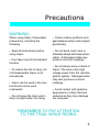
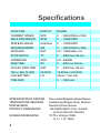
Table of Contents
Page #
Table of Contents
1
A Note To You
2
Precautions
3
SPECIFICATIONS
4
Overview
6
Installation
9
Measure Wheel Size
14
Data Setting Mode
16
Normal Mode Screens
28
VAPOR FEATURES
30
Troubleshooting
40
Glossary of Terms
42
1
A Note to You
Thanks for Buying a Trail Tech
Powersport Computer:
Trail Tech powersport computers bring functionality and life to your
motor vehicle with high quality and innovation. To ensure you enjoy
years of trouble-free operation, this user’s manual contains valuable
information about how to operate and maintain your computer properly.
Please read this manual carefully.
Please Record Important Information:
Whenever you call to request service for Vapor, you need to know the
date of purchase, dealer’s name, address, and telephone number.
PURCHASE DATE
DEALER NAME
DEALER ADDRESS
DEALER PHONE
Keep this book and sales slip together for future reference.
2
Precautions
WARNING:
When using Vapor, follow basic
precautions, including the
following:
• Check relative positions and
gap between sensor and magnet
periodically.
• Read all instructions before
using Vapor.
• Do not bend, twist, kink or
otherwise abuse the black sensor
cable. A damaged cable may
produce incorrect readings.
• Use Vapor only for its intended
function.
• To reduce the risk of injury, do
not disassemble Vapor or its
accessories.
• Vapor can be used in the rain
but should not be used
underwater.
• Do not leave the main unit in
direct sunlight when not riding.
• Do not abuse wires on back of
Vapor. The wires carry high
voltage power from the vehicles
ignition system. Damaged wires
may also produce incorrect
readings.
• Avoid contact with gasoline,
degreasers or other chemical
cleaners as they may damage
the computer.
REMEMBER TO PAY ATTENTION
TO THE TRAIL WHILE RIDING.
3
Specifications
FUNCTION
DISPLAY
RANGE
CURRENT SPEED
SPD
4
- 399.9 KM/H or M/H
REVS PER MINUTE
RPM
0
- 19999 RPM
RPM BAR GRAPH
Graphical
0
- 12000 RPM
MAXIMUM SPEED
MS
4
- 399.9 KM/H or M/H
DISTANCE
DST
0.0 - 19999 KM or M
STOP WATCH
TT
0
ODOMETER
ODO
0.0 - 999999
RIDE TIME
RT
0
- 999 hour 59 min
ACCUM. RIDE TIME
ART
0
- 9999 hour 59 min
12H or 24H CLOCK
00:00:00
12:59:59 or 23:59:59
LOW BATTERY
LO
About 1 Year Life
TIRE SIZE
SPEED/DISTANCE SENSOR
TEMPERATURE SENSORS
RPM SENSOR
PRODUCT DIMENSIONS
SCREEN DIMENSIONS
4
0
- 9999 hour 59 min
- 3999 mm
Non-contact Magnetic Speed Sensor
Ambient and Engine Temp. Sensors
Electrical Pulse Sensor
106.93x59.46x23.7mm WxHxD
(4.21x2.34x0.93” WxHxD)
78.75 x 28.6mm WXH
(3.1 x 1.13” WxH)
Specifications
UNITS
INCREMENTS
ACCURACY
KM/H or M/H
0.1 KM/H or M/H
+/- 0.1%
KM/H or M/H
10 RPM
+/- 0.1%
KM/H or M/H
Variable
+/- 0.1%
KM/H or M/H
0.1 KM/H or M/H
+/- 0.1%
KM/H or M/H
0.1 KM/H or M/H
+/- 0.1%
Hours:Minutes
1 Second
+/- 0.1%
KM or M
1
+/- 0.1%
Hours:Minutes
1 Minute
+/- 0.1%
Hours:Minutes
1 Minute
+/- 0.1%
H:M:S
+/- 0.1%
2.5 Volts
+/- 0.1%
PRODUCT WEIGHT
WHEEL CIRCUMFERENCE
OPERATION TEMPERATURE
STORAGE TEMPERATURE
BATTERY
BATTERY LIFE
EXTERNAL POWER INPUT
3.9 oz. (110 grams) (0.24 lbs.)
0 to 3999 mm
0°C to 60°C (32°F to 140°F)
-20°C to 80°C (-4°F to 176°F)
3V CR2032
About 1 Year
9.0-400 VAC/VDC
(No polarity requirements.)
5
Overview
Vapor Computer:
Vapor holds a large amount of information in a small space. There
are three buttons for easy navigation, two LED’s for alerts and
warnings, and a brightly lit LCD panel for easy viewing.
YELLOW
LED
RED LED
LCD
SCREEN
LEFT BUTTON
MODE BUTTON
RIGHT BUTTON
Quickstart Commands:
• <MODE> = Switch between screens in Normal Mode.
• <LEFT> + <MODE> = Reset Trip Data: Maximum Speed, Distance,
Ride Time, Stop Watch, Max Engine Temperature, and Max RPM.
• <RIGHT> = Toggle between features in Normal Mode screens.
• <MODE> FOR 3 SEC = Edit Trip Distance (DST) value.
- <LEFT> or <RIGHT> = Increment or scroll distance value.
• <LEFT> <CENTER> + <RIGHT> = Enter Data Setting Mode.
- <MODE> = Move to next data setting screen.
- <LEFT> = Increment or scroll through current data setting.
- <RIGHT> = Move to next digit in data setting mode.
6
Parts & Features
Backlight:
Vapor is equipped with a backlight for easy viewing during night-time
operation.
Using External 12V Power:
• Vapor will light up with all five LED’s.
• Vapor will remain lit as long as it senses wheel movement. After
20 minutes of inactivity Vapor shuts off the backlight. Press any
button, roll the wheels, or start the motor power and Vapor will light
up again.
• Shift and Temperature LED’s will be enabled.
Using Internal Battery Only:
• Vapor will only stay lit for 3 seconds.
• Vapor’s backlight will light up with 10% power to conserve battery
power.
• If the LO symbol is present, the backlight will not turn on. The LO
symbol appears when battery voltage drops below 2.45V.
• If ambient temperature is cold (below -5°C) the backlight will not
TO ACTIVATE BACKLIGHT MANUALLY, PRESS
If connected to 12V power, press any key to activate the backlight.
7
Parts & Features
Reset Button:
Use of the Reset Button will erase data for the current ride including
clock and trip distance.
RESET
BUTTON
BATTERY
MOUNTING
HOLES
Internal Battery:
Vapor has an internal 3.0V watch type battery (#CR2032). The
computer can be run from this battery alone.
To change the battery, unscrew the battery cap on the back of the
computer with a coin. Make sure the positive side of the battery is
facing up when replaced.
REPLACE WITH BATTERY MODEL NUMBER #CR2032
8
Installation
Bar Mounting:
Place bolts as
shown in picture.
Remember to
use provided
nuts when
placing bolts.
RPM and Temperature Sensors:
Please see model-specific instructions for mounting procedure.
Motorcycle installation shown below.
RPM
SENSOR
COIL
SPARK PLUG
BOOT
RPM Pulse Sensor
wrapped around spark plug wire
RADIATOR
HOSE
TEMP.
SENSOR
Temperature Sensor
in-line in radiator hose
9
Installation
DRILL TEMPLATE
SCALE 1:1
Flat/Surface Mount:
There are two screw holes on
the back of Vapor. Use the
included M4 bolts to mount to
any flat surface (e.g. stock
odometer mounting bracket or
body panel).
40mm
Make sure that the cables will
not be chafed or damaged in
their mounting location.
Drill Size:
• 4.2mm
• 0.165”
• M4
If other than provided screws
are used, make sure they are
not too long for mounting holes.
Screws that are too long will
damage internal components of
Vapor.
107.5mm
59.5mm
Mounting
Hole
Accepts
M4 Bolts
10
40mm
Installation
12 Volt Systems:
If possible, install Vapor to a 12
volt system:
• The backlight will be 10 times
brighter.
• Vapor will enter sleep mode
after 20 minutes instead of 5.
• The shift and and temperature
indicator LED’s will be
enabled.
OPTION 1) BATTERY WIRED:
Connect the power cables
directly to the vehicle’s 12 volt battery. A 0.5A fuse (not provided)
should be used between the power cable and positve battery terminal
when connecting directly to a battery.
OPTION 2) SYSTEM TAP:
As an alternative to running wires all the way to the battery, it is
possible to tap into the electrical system. When tapping into the
electrical system, connect to a circuit protected by fuse. It is best to
connect so power is not interrupted by key switch.
Notes:
• Vapor is polarity independent. Either lead can go to the positive or
negative post on the battery.
• Vapor will not drain your battery.
• The “LO” low battery indicator will activate if battery voltage drops
11
Installation
ATV Sensor/Magnet Installation:
Vapor needs two things to be
able to collect distance data:
1. A magnet placed on the
spinning part of the wheel.
2. The sensor, placed on the
non-moving part of the wheel.
The magnet spins around
tripping the sensor switch
each time--data collected lets
Vapor calculate distance and
time.
Magnetic Bolt Installation
ATV Rotor
The magnet gets installed on the brake rotor because it spins with
the wheel. Typically the provided magnetic bolt can simply replace
a stock rotor bolt (see above picture). If that doesn’t work, there is
a spare magnet that can be
glued in a hole on the brake
rotor. (JB Weld or a similar
slow-cure epoxy works
well.)
After the magnet is in, the
sensor is placed on a nonspinning part the wheel.
C-Bracket Installation-ATV Left Axle
12
The sensor typically is
placed on either the
provided C-bracket or the
ATV metal rotor shield.
Installation
Motorcycle Sensor/Magnet Installation:
Motorcycles, like ATV’s,
need a magnet placed on
the spinning part of the
wheel and the sensor
installed to a non-spinning
part.
The magnet typically gets
bolted or glued to the
brake rotor.
The sensor wire should
come from the back of the
computer, be cable-tied to
the brake line as it travels
down the front forks, then
attached to the brake
caliper.
Magnet About to Pass Under Sensor
Vapor can tell how far and fast
it’s traveled by keeping track of
how many times the magnet
passes under the sensor switch.
Optimum Magnet Rotation Path
Many Motorcycles and ATV’s
have special installation
procedures. Refer to the
provided installation insert for
specific instructions for your
machine or visit
www.TrailTech.net.
13
Installation
Overview:
You will use the wheel size number when setting up the computer for
your machine. Use Method 1, 2 or 3.
Method 1)
Easy Ruler
Method:
Find the
circumference
of front wheel
by measuring
its diameter in
millimeters. Multiply
the Wheel Diameter
by 3.14. The result is your
wheel size.
Wheel Size=
Wheel Diameter(mm)
x 3.14
Diameter(mm)
x 3.14
Method 2)
Rolling Measurements:
On a flat surface, mark the tire sidewall and the ground with a marking
pen. Roll the wheel until the mark on the tire completes one revolution
and is back on the ground. Mark the ground at this location. Measure
the distance between the marks on the ground and convert the
measurement to mm (multiply inches by 25.4). Use this number for
your wheel size. For accuracy, the rider’s weight should be on the
bike when making this measurement.
14
Installation
Method 3) Distance Measurements:
For the most accurate measurement, use wheel size measurement
from above or set the wheel size to 2110mm (motorcycle) or 1675
(ATV) and follow this procedure:
1. Find a length of road where the distance is known.
2. Ride the distance and note the distance the computer reads (for
example, the road is known to be 5 miles and the computer shows
4.95 miles.)
3. Use the numbers to solve for X in the following equation:
2110
X
=
4.95
5.00
or
(current wheel size)
(new wheel size)
=
(current miles)
(actual miles)
4.95X = 2110 * 5.00
4.95X = 10550
X=
10550
4.95
X = 2131
4. Enter number found from the above method in your computer.
My Wheel
Size:
15
Data Setting Mode
Overview:
Data Setting Mode is very important for Vapor to operate
correctly.
Available Settings:
• Kilometers or Miles per Hour
• Wheel Size in Millimeters
• 24 hour or 12 hour Clock Format
• Time of Day
• Pulses per Revolution (PPR)
• Temperature Unit of Measure, °F or °C
• High Temperature Warning Point
• Over Temperature Danger Point
• RPM Shift Indicator
• Over Shift Indicator Warning
Hold all three buttons down for three seconds to enter
Data Setting Mode.
After a setting is confirmed, Vapor will move on to the next
setting in order.
If no button is pressed for 15 seconds, Vapor will return
to Normal Mode.
16
Data Setting Mode
Enter Data Setting Mode:
TO ENTER DATA SETTING
MODE, HOLD ALL THREE
BUTTONS FOR 3 SEC
Release buttons to
continue.
Program Kilometers or Miles Per Hour:
TO CYCLE BETWEEN M/H AND KM/H, PRESS
TO CONFIRM, PRESS
Vapor will go to the next setting.
17
Data Setting Mode
Program Wheel Size:
Vapor needs to know wheel size in order to measure Distance and
Speed. Please take the time to accurately measure wheel size for
smooth operation. See “Measuring Wheel Size” section for more
information. This setting is critical and required.
USE AS DEFAULTS: MOTORCYCLE - 2110mm
ATV - 1676mm
MODIFY FLASHING DIGIT BY PRESSING
CHANGE TO NEXT DIGIT BY PRESSING
TO CONFIRM, PRESS
Vapor will go to the next setting.
18
Data Setting Mode
Program 12 or 24 Hour Clock Format:
Vapor defaults to 12H format.
TO CYCLE BETWEEN 12H AND 24H, PRESS
TO CONFIRM, PRESS
Vapor will go to the next setting.
Program Time of Day:
MODIFY FLASHING DIGIT BY PRESSING
CHANGE TO NEXT DIGIT BY PRESSING
TO CONFIRM, PRESS
Vapor will go on to the next setting.
19
Data Setting Mode
Program Pulses per Revolution (PPR)
Step 1:
Every time the engine revolves it sends a pulse to Vapor, letting it
know how fast the engine is turning. The number of ignition pulses
per revolution will vary across different engine types. Select from 0.5,
1.0, or 2.0 PPR. This setting is critical.
USE AS DEFAULTS: 4 Strokes:
2 Strokes:
1 PPR
1 PPR
MODIFY FLASHING DIGIT BY PRESSING
CHANGE TO NEXT DIGIT BY PRESSING
TO CONFIRM, PRESS
Vapor will go to the next setting.
20
Data Setting Mode
Program Pulses per Revolution (PPR)
Step 2:
For most vehicles, press MODE to continue. Some vehicles change
PPR over a certain RPM. For these vehicles, change the displayed
RPM digits to the RPM at which the vehicle changes PPR.
MODIFY FLASHING DIGIT BY PRESSING
CHANGE TO NEXT DIGIT BY PRESSING
TO CONFIRM, PRESS
Vapor will go to the next setting.
21
Data Setting Mode
Program Pulses per Revolution (PPR)
Step 3:
This screen will appear if a number other than zero is entered in
previous step.
Vapor will flash the default number “1.0”. Typically, a vehicle that
changes PPR ratio at higher RPM’s changes from 0.5 to 1.0. Consult
your bike’s User Manual or the manufacturer for details.
MODIFY FLASHING DIGIT BY PRESSING
CHANGE TO NEXT DIGIT BY PRESSING
TO CONFIRM, PRESS
Vapor will go to the next setting.
22
Data Setting Mode
Program Temperature Unit of Measure:
Choose between °C or °F.
MODIFY FLASHING DIGIT BY PRESSING
CHANGE TO NEXT DIGIT BY PRESSING
TO CONFIRM, PRESS
Vapor will go to the next setting.
23
Data Setting Mode
Program High Temp Warning Point:
Vapor defaults to 90°C (190°F). When the engine temperature sensor
reaches the value of this setting, the left LED will turn on as a warning.
Note: This step is only neccessary if an optional engine temperature
sensor is installed.
Vapor defaults to 0.
MODIFY FLASHING DIGIT BY PRESSING
CHANGE TO NEXT DIGIT BY PRESSING
TO CONFIRM, PRESS
Vapor will go to the next setting.
24
Data Setting Mode
Program Over Temp Danger Point:
Vapor defaults to 110°C (230°F). When the engine temperature sensor
reaches the value of this setting, the right LED will turn on as a critical
warning alarm. This step is only neccessary if an optional engine
temperature sensor is installed.
Vapor defaults to 0.
MODIFY FLASHING DIGIT BY PRESSING
CHANGE TO NEXT DIGIT BY PRESSING
TO CONFIRM, PRESS
Vapor will go to the next setting.
25
Data Setting Mode
Program RPM Shift Indicator:
Vapor’s shift indicator defaults to 6000 RPM.
The left LED will flash when it’s time to shift.
Vapor defaults to 0.
MODIFY FLASHING DIGIT BY PRESSING
CHANGE TO NEXT DIGIT BY PRESSING
TO CONFIRM, PRESS
Vapor will go to the next setting.
26
Data Setting Mode
Program Over Shift Indicator Warning:
Vapor’s over shift warning indicator defaults to 10,000 RPM.
The right LED will flash when the engine is revving too high.
Vapor defaults to 0.
MODIFY FLASHING DIGIT BY PRESSING
CHANGE TO NEXT DIGIT BY PRESSING
TO CONFIRM, PRESS
Vapor will return to Normal Mode.
27
Normal Mode Screens
Switch between the 3 Normal Mode Screens:
All of the information that Vapor provides is on one of these 3 screens.
When riding, the user has the choice of staying on Screen 1 or
Screen 2. Screen 3 will default back to Screen 1 after 5 seconds.
TO SWITCH BETWEEN SCREENS, PRESS
Screen
1 Displays:
Screen
1:
• Speed (SPD) • Distance (DST)
• Time of Day • Ambient Air Temperature • RPM Bar Graph
28
Normal Mode
Screen 2:
Screen 2 Displays:
• Speed (SPD) • Revolutions per Minute (RPM)
• Stop Watch (TT) • Ride Time (RT)
• Engine Temperature* • RPM Bar Graph
TOGGLE BETWEEN
STOP WATCH AND
Ride TIME BY
PRESSING
Screen 3:
Screen 3 Displays:
• Maximum Speed (MS) • Maximum RPM (MR)
• Accumulated Ride Time (ART) • Odometer (ODO)
• Maximum Temperature (MAX)*
TOGGLE BETWEEN
ACCUMULATED
RIDE TIME AND
ODOMETER BY
PRESSING
*Note: Engine Temperature readings require optional sensor.
29
Vapor Features
Overview:
Vapor is in Normal Mode during regular use.
Available Features:
• Sleep Mode
• RPM Bar Graph
• Stop Watch (TT)
• Switch between the 3 Normal Mode Screens
• Reset single-ride data to zero
• Shift Indicators
• Ambient and Engine Temperature
Sleep Mode:
If Vapor receives no data for 20 minutes (either wheel data or a button
pressed), it will enter sleep mode. It will only display the clock while
in Sleep Mode. It will exit Sleep Mode when it receives sensor data
or a button is pressed.
30
Vapor Features
Tachometer:
Description:
The tachometer provides both a graphical and
numeric display of engine RPM. The LCD display
is designed to display a segmented bar graph
for information at a glance as well as a numeric
display for more accurate readings.
Bar Graph:
The RPM bar graph will progressively light up
as RPM increases. The resolution of each
segment varies in order to emphasize the most
useful and important ranges of RPM.
Resolution of each segment on RPM bar graph:
• 0-2000 rpm:
250 rpm/seg
• 2000-4000 rpm:
500 rpm/seg
• 4000-6000 rpm
200 rpm/seg
• 6000-9000 rpm
125 rpm/seg
• 9000-12,000 rpm 375 rpm/seg
Display:
Screen 1: RPM Bar Graph
Screen 2: RPM Bar Graph, Numeric RPM
Screen 3: Maximum RPM
31
Vapor Features
Speedometer:
Description:
The speedometer shows the current vehicle
speed. Vapor also shows Maximum Speed, the
highest speed achieved since the last reset.
Speed:
Speed is displayed from 0 to 399.9 M/H or KM/H
in the center of Screens 1 and 2. The SPD icon
and KM/H or M/H will also appear next to the
speed reading.
Maximum Speed:
Maximum speed is displayed on Screen 3 in the
middle next to the MS icon. Maximum speed is
reset by a trip-data reset <LEFT> + <MODE>.
32
Vapor Features
Adjustable Trip Distance Meter:
Description:
The Trip Meter shows how much distance has
been travelled since the last reset.
Trip Distance:
Trip Distance is displayed from 0 to 9999.9 miles
or kilometers in the lower right of Screen 1, next
to the DST icon. Trip Distance is reset by a tripdata reset <LEFT> + <MODE>.
Adjustable Trip
Distance:
Trip Distance is adjustable in 0.1 KM or M
increments. Hold <MODE> for 3 seconds on
any Normal Mode screen, then scroll Trip
Distance up with the <LEFT> button or down
with the <RIGHT> button.
ENTER DISTANCE EDIT MODE FROM ANY
SCREEN BY HOLDING <MODE> FOR 2 SECONDS
INCREMENT OR SCROLL DISTANCE VALUE
BY PRESSING <LEFT> OR <RIGHT>
Hold the button down and Vapor will scroll faster.
33
Vapor Features
Odometer:
Description:
The Odometer will provide the user with a numeric
display of total accumulated distance in miles or
kilometers. The odometer is not resettable.
Display:
The highest Odometer reading Vapor can display
is 999,999 miles or kilometers.
The Odometer is shown only on Screen 3 and
alternates with Accumulated Ride Time (ART)
by pressing <RIGHT>.
34
Vapor Features
Accumulated Ride Time
Description:
Accumulated Ride Time (ART) tracks the total
amount of time the engine has been turned on.
Accumulated Ride Time is not resettable.
Display:
The highest Accumulated Ride Time Vapor can
display is 9999:59 hours (when the maximum
value is reached, Vapor will not roll the number
back to 0).
Accumulated Ride Time (ART) is shown only on
Screen 3 and alternates with the Odometer
(ODO) by pressing <RIGHT>.
Note:
Accumulated Ride Time increments whenever
RPM data is present (the vehicle is turned on.)
35
Vapor Features
Clock, Stop Watch, and Ride Time:
Time-of-Day Clock: The Time-of-Day clock is displayed in the upperright corner of Screen 1 next to the clock icon
and during Sleep Mode. The clock is displayed
in either 12H or 24H format.
Ride Time:
Time (RT) is displayed in the upper right corner
of screen 2. Ride Time shows how long the
engine has been running since the last reset.
Ride Time is reset by a trip-data reset <LEFT>
+ <MODE>.
Toggle between Ride Time and Stop Watch on
Screen 2 by pressing <RIGHT>.
Stop Watch:
The Stop Watch (TT) functions like any simple
stop watch. Press <LEFT> to start or stop the
Stop Watch.
Toggle between Stop Watch and Ride Time on
Screen 2 by pressing <RIGHT>
36
Vapor Features
Ambient Air Temperature/
Engine Temperature:
Vapor will display ambient or air temperature on Screen 1. If an
optional engine temperature sensor has been installed on the machine,
Vapor will display engine temperature on Screen 2. Screen 3 will
display the maximum engine temperature received by the sensor
since the last reset (see Normal Mode:Reset Single-Ride Data for
details).
Temperature measurements use user defined values to advise when
the engine is getting too hot. Tell Vapor what is too hot in Data Setting
Mode (see Data Setting Mode:Temperature Settings for more detail).
When Temperature reaches Vapor’s High Temp Setting, the left LED
will light steady on, signaling the bike is starting to get too hot.
When Temperature reaches Vapor’s Danger Temp Setting, the right
LED will light steady on, signaling the bike is dangerously hot.
Vapor says,
“DANGER TOO HOT!”
Vapor must be connected to external power or LED’s will not function.
NOTE: Engine temperature data will override shift points.
37
Normal Mode
Shift Indicator Lights:
The Shift Indicator Lights use user defined values to advise when it’s
time to shift. Tell Vapor when to shift in Data Setting Mode (see Data
Setting Mode:Shift Indicator Settings for more detail).
When RPM reaches Vapor’s RPM Shift Indicator Warning Value, the
left LED will flash, signaling it’s time to shift.
(Default value is 8,000 RPM).
When RPM reaches Vapor’s RPM Over Shift Indicator Danger Value,
the right LED will flash, signaling the bike is revving too high.
(Default value is 12,000 RPM).
Vapor says,
“Time to Shift!”
Vapor says,
“DANGER Shift NOW!”
NOTE: Engine temperature data will override shift points.
38
Normal Mode
Reset Single-Ride Data to Zero:
Resets temporary data:
• Maximum Speed (MS) • Distance (DST)
• Stop Watch (TT) • Maximum Temperature (MAX)
• Maximum RPM (MR)
This data should be reset to zero at the completion of a ride so that
new information can be logged on the next ride.
Notes:
• The reset can be done from any screen.
• Accumulated Ride Time (ART) and Odometer (ODO) cannot be
reset and are intended to maintain cumulative information.
TO RESET SINGLE-RIDE DATA, PRESS
If any wires become unplugged from Vapor, do a data reset after
everything is properly re-connected. Alternatively, push the red reset
button on the back of Vapor.
39
Troubleshooting F.A.Q.
Frequently Asked Questions:
Why does nothing work?
The internal battery may be dead, or Vapor is not hooked up to vehicle
power properly. Review installation procedure. Try the reset button
on the back of Vapor. Don’t forget to write down your wheel size and
other settings beforehand.
Why doesn’t the engine temperature feature work?
You must have the optional temperature sensor installed correctly for
this feature to function. Review installation procedure. If the cable
has become disconnected, push the reset button on the back of Vapor
after reconnecting.
Why isn’t the RPM Graph working?
The engine sensor may be installed incorrectly. Review installation
procedure.
Everything is working, but the (K)MPH reading is way off!
The wheel sensor/magnet may be installed incorrectly. Double check
to make sure everything is set up right.
The wheel size setting may be incorrect. Please review wheel size
measurement instructions in this manual.
Vapor is not displaying information correctly!
If the wires on the back of Vapor become damaged, incorrect readings
may be displayed. Be careful to avoid twisting, crimping, kinking or
otherwise abusing the wires.
40
Troubleshooting
The screen melted!
Did gasoline, degreasers, or other chemical cleaners come in contact
with Vapor’s screen? Some chemicals can easily damage Vapor.
Why is the LCD Display slow, or even worse, black?!
Vapor may have been exposed to too much direct sunlight while not
riding or temperatures below 0°C. Try the reset button and get Vapor
back to a normal temperature.
The Backlight won’t stay lit!!!
Vapor needs to be connected to vehicle’s 12 volt system in order for
the backlight to be continuous on. Review installation procedure.
Vapor’s internal battery is dead!
To replace the battery, use a coin to unscrew the round panel on the
back of Vapor. Remove the old battery and install the new one. Make
sure the positive pole is facing up. Replace with common watch
battery CR2302.
Why aren’t the LED’s working?
Vapor needs to be connected to vehicle’s 12 volt system in order for
the LED’s to function.
The temeperature LED’s require an optional engine temperature
sensor to be installed correctly and must be set in Data Setting Mode
correctly. They default to 0, in effect turned off.
The shift points must be set correctly in Data Setting Mode to function
correctly. They default to 0, in effect turned off.
REMEMBER TO PAY ATTENTION
TO THE TRAIL WHILE RIDING.
41
Normal Mode
Glossary of Terms
ACCUMULATED RIDE TIME (ART)
The long-term total amount of time spent riding (all ride times added
together). Cannot be reset.
BACKLIGHT
The light that brightens up Vapors display. When connected to vehicle’s
12 volt system the backlight can be activated by pressing any button,
will be 5 times brighter, and will stay on continuously.
SPEED (SPD)
The current speed the vehicle is traveling.
DATA SETTING MODE
The place to set Vapors’ settings. Includes distance units, wheel size,
clock format, time, PPR, temperature units, high temp setting, over
temp setting, RPM shift indicator and RPM over shift indicator.
DISTANCE (DST)
The amount of trail covered since the last reset.
HIGH/OVER TEMP INDICATORS
The LED’s will blink when the bike gets too hot and again when it gets
dangerously hot. Set custom temperatures in Data Setting Mode.
MAXIMUM SPEED (MS)
The max speed achieved since the last reset.
42
Glossary of Terms
NORMAL MODE
Vapor’s standard mode.
REVOLUTIONS PER MINUTE (RPM)
The number of revolutions the engine makes in a minute. Revolutions
Per Minute is commonly abbreviated to RPM.
RPM BAR GRAPH
The graphical display on Vapor’s screen that represents engine
revolutions.
RPM SHIFT INDICATORS
The LED’s will light up when it’s time to shift and again when RPM’s
hit the danger point. Set custom RPM limits in Data Setting Mode.
SENSOR
Vapors’ various sensors must be installed correctly or nothing will
work! One works with the magnet to let Vapor collect its wheel data,
another gets connected to the engine to measure PPR, and a third
sensor will measure the temperature.
SLEEP MODE
If Vapor doesn’t receive any sensory information it will go into Sleep
Mode and only display the clock. Press any button to exit.
STOP WATCH (TT)
A short term, regular stop watch.
WHEEL SIZE
Very important. Used to determine speed and distance. Refer to the
Wheel Measurement section for an accurate measurement.
43
Notes
Notes:
44
NOTES
OTHER PRODUCTS BY
45
LIMITED WARRANTY
Within 180 days from the date of original purchase, Trail Tech will
repair or replace, at its option, any Trail Tech powersport computer
which is deemed defective in workmanship or materials.
Please return the unit, together with proof of date of purchase, to your
local dealer or send unit (postage paid) to Trail Tech.
Damage or injuries resulting from negligence or misuse are not covered
by this warranty. Incidental or consequential damages are specifically
excluded.* This warranty gives you specific legal rights. You may
also have other rights which vary from state to state. *Because some
states do not allow the exclusion of incidental or consequential
damages, this exclusion may not apply to you.
MADE IN AMERICA
Trail Tech and Vapor are
trademarks of Trail Tech, Inc.
www.trailtech.net
360-687-4530