1
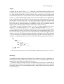
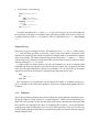
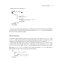
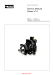
Original citation:
Giridhar, P., Kumar, V. and Joseph, M. (1997) The mine pump problem. University of
Warwick. Department of Computer Science. (Department of Computer Science
Research Report). (Unpublished) CS-RR-332
Permanent WRAP url:
http://wrap.warwick.ac.uk/61019
Copyright and reuse:
The Warwick Research Archive Portal (WRAP) makes this work by researchers of the
University of Warwick available open access under the following conditions. Copyright ©
and all moral rights to the version of the paper presented here belong to the individual
author(s) and/or other copyright owners. To the extent reasonable and practicable the
material made available in WRAP has been checked for eligibility before being made
available.
Copies of full items can be used for personal research or study, educational, or not-forprofit purposes without prior permission or charge. Provided that the authors, title and
full bibliographic details are credited, a hyperlink and/or URL is given for the original
metadata page and the content is not changed in any way.
A note on versions:
The version presented in WRAP is the published version or, version of record, and may
be cited as it appears here.For more information, please contact the WRAP Team at:
[email protected]
http://wrap.warwick.ac.uk/
The Mine Pump Problem
(This description is taken from Real-time Systems: Specification, Verification and Analysis, (Joseph, 1996).)
Water percolating into a mine is collected in a sump to be pumped out of the mine
(see Figure 1). The water level sensors D and E detect when water is above a high and a
low level respectively. A pump controller switches the pump on when the water reaches
the high water level and off when it goes below the low water level. If, due to a failure
of the pump, the water cannot be pumped out, the mine must be evacuated within one
hour.
The mine has other sensors (A, B, C) to monitor the carbon monoxide, methane and
airflow levels. An alarm must be raised and the operator informed within one second of
any of these levels becoming critical so that the mine can be evacuated within one hour.
To avoid the risk of explosion, the pump must be operated only when the methane level
is below a critical level.
Human operators can also control the operation of the pump, but within limits. An
operator can switch the pump on or off if the water is between the low and high water
levels. A special operator, the supervisor, can switch the pump on or off without this
restriction. In all cases, the methane level must be below its critical level if the pump is
to be operated.
Readings from all sensors, and a record of the operation of the pump, must be logged
for later analysis.
Safety requirements
From the informal description of the mine pump and its operations we obtain the following safety requirements:
1. The pump must not be operated if the methane level is critical.
2. The mine must be evacuated within one hour of the pump failing.
3. Alarms must be raised if the methane level, the carbon monoxide level or the
airflow level is critical.
1
2
Operator
A
B
C
D
E
Log
Carbon Monoxide sensor
Methane sensor
Air f low sensor
High water sensor
Low water sensor
Pump Controller
1 1
0
0
0
1
0
1
0
1
0
111 1
000
Pump
0 1
1
0
0
1
0
1
0
1
0 B1
1
0C
0
1
A
1
0
1
0
0
1
0
1
0
1
0
1
0
1
0
1
0
1
0
1
D
0
1
0 E
1
Sump
Figure 1 Mine pump and control system (adapted from Burns and Lister, 1991)
Operational requirement
The mine is normally operated for three shifts a day, and the objective is for no more
than one shift in 1000 to be lost due to high water levels.
The following pages describe the development of a mine pump program
in Esterel. This account complements the other versions given in the book
Real-time Systems: Specification, Verification and Analysis, (Joseph, 1996).
The interested reader may wish to note that this material has been written
to follow the description of the problem given in Chapter 1 of the book and
to precede the introduction to scheduling theory given there in Chapter 2.
Chapter 1
Synchronous Programming
P. Giridhar, Vinod Kumar and Mathai Joseph
Introduction
A reactive system maintains continuous interaction with its environment by sending
outputs in response to inputs from devices like sensors and process controllers. The
behaviour of such a system is the relationship between inputs and outputs. Inputs may
come also from timers, allowing the system to align its actions with external clocks and
provide real-time responses. The class of reactive systems includes communication protocols, user interfaces and real-time systems in process control, avionics and bio-medical
instrumentation.
In this chapter, we introduce the synchronous programming language Esterel for the
specification and verification of behaviour of reactive systems. An Esterel program reacts to an input event(s) by performing computations (e.g. updating local variables, invoking procedures or functions etc.) and emitting local and external output signals. It is
assumed that this reaction is instantaneous, i.e. s are synchronous with inputs and they
occur in the same instant as inputs. A consequence of this assumption is that reactions
are expected to take ‘no time’ with respect to the rate of change of the environment, i.e.
the reaction to an input event should be completed before next input event arrives. This
requirement poses no problems for specification and verification, but the implementation that guarantees this requirement may not always be efficient. However, synchronous
programs have the following advantages where this requirement can be satisfied:
it is easy to write such programs and verify them,
they can be compiled into very efficient automata, and
they are independent of implementation details.
The synchrony assumption is realized by the instantaneous broadcasting of signals
and translation of Esterel programs to efficient finite automata.
3
4 Synchronous Programming
1.1 Esterel Language
The basic unit of an Esterel program is a module. It consists of declarations of the objects
(signals, variables etc.) used in the module and the body, containing Esterel statements.
The language has imperative statements such as assignment, loops and statement composition operators, and temporal statements such as triggers, watchdogs and temporal
loops. In the rest of this section, the basic constructs of Esterel are presented. A comprehensive list of the constructs and their semantics can be found in [1] and in the Esterel
language reference manual.
Esterel supports modular development and, to some extent, successive refinement of
programs. Problem can be decomposed into various components, each of which can be
specified in a module. These modules can be composed in sequence, or in parallel using
the keyword run.
1.1.1 Imperative Statements
The imperative statements of Esterel are similar to those of other languages: there is a
null statement (nothing), a halting statement (halt) and assignment (:=), conditional (if ...
then ... else) and iteration (loop,repeat) statements. Other statements for signal emission
(emit), testing the presence of a signal (present ... then ... else), procedure invocation
(call), function invocation. With the exception of halt, the other statements are treated
as though they terminate instantaneously. Procedures and functions are assumed to be
implemented in a host language; care must be taken to ensure that their execution time
is small enough for them to be treated as if they terminate instantaneously.
The parallel operator (||) terminates when all its branches have terminated. Thus
if there are temporal statements in a branch, it may not terminate instantaneously. The
sequencing operator has precedence over the parallel operator. The trap statement (trap
T in ... exit T ... end) terminates either when its body terminates or when an exit statement
is executed in the body. A handler can optionally be specified for a trap. If a trap is exited
through an exit statement, the corresponding handler, if present, is executed. When more
than one trap is exited in the same instant (in parallel branches), the outermost trap only
is exited; the others are discarded.
1.1.2 Temporal Statements
A temporal statement in Esterel is used to specify an action which depends on the occurrence of an input event in the environment. Unlike imperative statements, temporal
statements may take one or more instants to finish.
There are three kinds of basic temporal statements: triggers (await), watchdogs (do
stat watching event) and temporal loops (every event do stat end), where stat is
compound statement.
Esterel Language 5
Trigger
A trigger has the form: await event. It halts the execution until the specified event
occurs. In this basic form, execution will wait for the next occurrence of an input event:
e.g. await Second will halt the execution until the next occurrence of the event Second.
To test for the presence of an event in the current instant, the qualifier immediate must
be used: e.g. await immediate RejectSample will terminate instantaneously if RejectSample
event is already present and will wait for its next occurrence if it is not present. An event
can also have an occurrence count: e.g. await 1000 Second will halt the execution until
the Second event occurs 1000 times. The immediate qualifier and the occurrence count
can be used in any temporal statement. In addition, events can be combined with the
logical operators and, or and not using an expression in square brackets.
The trigger can also be written as await event do stat end to emphasize the dependency of stat on the occurrence of event. This is equivalent to await event; stat.
The most general form of trigger is a multiple await. This is used to specify triggers
for more than one event. If any of the events occurs, the corresponding trigger is executed. If more than one input event occurs simultaneously, only the first trigger for these
events is executed. Thus Esterel guarantees that the reactions are always deterministic
– for the same inputs, an Esterel program will always produce the same outputs. For
example, a vending machine that serves tea and coffee can be programmed as follows:
loop
await Coin ;
await
case Tea do
emit ServeTea ;
case Coffee do
emit ServeCoffee ;
end await ;
end loop ;
If the customer presses the tea and coffee buttons simultaneously, only tea is served.
Watchdog
A watchdog specifies an upper time limit for the execution of a body of statements. If
the body does not finish before the time limit, its execution is terminated and the timeout
trigger for the time limit is executed, if there is one.
Consider a railway crossing controller. A command to close the gate is issued when a
train is detected. If the gate closes within 2 minutes from that time, the train is allowed
to continue; otherwise, it is assumed that the gate is faulty and the train is stopped before
it reaches the gate.
6 Synchronous Programming
await TrainArrived ;
do
emit CloseGate ;
await GateClosed ;
watching 2 minute
timeout
emit StopTrain ;
end timeout ;
A similar statement, do stat upto event, can be used to give an exact time limit for
the execution of the body. It terminates only when the specified event occurs; it does not
terminate when the body stat terminates. This is equivalent to do stat ; halt watching
event.
Temporal Loop
There are two types of temporal loops. The statement, every event do stat end, executes
stat each time that specified event occurs. If the event occurs before execution of the
statement is completed, the current execution is terminated and a new execution is started
in the same instant. The other temporal loop has the form, loop stat each event. This is
similar to the every statement, except that in this case the first execution of the loop starts
without waiting for event to occur.
A signal (either an input signal set by the environment or a local or output signal
emitted by the Esterel program) is present for only one instant. An exception to this rule
is the special signal tick which is present at all instants. If it is necessary for an output
signal to be present at all instants, a temporal loop using tick can be used:
loop
emit event ;
each tick;
This construct is so useful that a special keyword, sustain, is available for this purpose; it should be clear from the semantics of the loop construct that sustain will never
terminate.
1.1.3 Semantics
The perfect synchrony abstraction of Esterel helps the system designer in uniquely specifying the response of the system to an input sequence. With a non-synchronous program, this is not possible as the interleavings of the inputs, internal state transitions and
the responses are depend on the delay in computing the response. A non-synchronous
program may behave differently if it is run on a faster processor. This is never the case
for an Esterel program and this fact is constructively made use of by the Esterel compiler
and the analysis tools.
Esterel Language 7
Consider the following non-reactive program.
module Nonreactive:
output S;
present S else emit S end;
end module;
If it is assumed that S is present when the test is performed, the emit S command will
not be executed and S will not be present. On the other hand, if S is assumed to be absent
then S will be emitted and hence will be present.
An Esterel program is logically reactive if the assumed presence of each signal corresponds to execution of an emit of the corresponding signal; a signal is absent if there
is no execution of an emit of that signal. Further, a program is logically deterministic
if only one set of signals is present. By contrast, the following is a non-deterministic
program as S could be present or absent.
module Nondeterministic:
output S;
present S then emit S end;
end module
An Esterel program is logically correct if it is logically reactive and logically deterministic with respect to all possible input events. However, logical correctness has to be
strengthened to take account of cause and effect. Otherwise, a logically correct program
could be written where signals are present or absent, satisfying the logical dependencies
of the program, but which cannot be explained in terms of cause and effect. The signals
in Esterel program must not only satisfy a set of equations but they should characterize
the intentions of the system designer about how the system should react to inputs.
A closer look at the nonreactive and non-deterministic programs shows that the assumption of instantaneous feedback is at the root of the problem. Earlier versions of
the Esterel (v4) compiler prevented instantaneous feedback altogether by first doing a
static analysis of the program. This had also the effect of preventing Esterel users from
writing programs with natural cyclic dependencies. The next version of the Esterel compiler (v5) used a dynamic analysis to permit constructive, reactive and deterministic to
be compiled. The analysis is constructive as no self-justifying assumptions are made.
Instead facts are propagated from known signal statuses to progressively and recursively
determine all signal states depending on what the program must do and what it cannot
do. Non-reactive and non-deterministic programs are rejected by this analysis. If the
analysis reaches a dead end when no further signal states can be inferred, the program is
considered to be non-constructive (Berry, 1996).
Accepting and rejecting programs based on the must and cannot predicates is the basis
for the constructive behavioral semantics of Esterel. Another method uses constructive
operational semantics where signal statuses are given values and the program code is
emulated through a series of micro steps. Clearly, each signal is ternary valued during
the emulation: present, absent or unknown. A third third method uses circuit semantics
to translate the program into Boolean digital circuits which define a cause and effect relation between Boolean variables. The solution of the circuit equations gives the logical
behavior of the program.
8 Synchronous Programming
1.2 The Mine Pump
The mine pump has been described in the introductory part of this report. Here the mine
pump is programmed in Esterel and the program is shown to meet its requirements. In
addition, some fault-tolerance is included in the system, so that it continues to perform
in spite of the occurrence of certain failures.
There are four major components in the system:
the pump controller,
the environment monitor subsystem consisting of monitors for carbon monoxide,
methane, airflow and the water level,
the data-logging subsystem, and
the operator subsystem.
For simplicity, the data-logging subsystem is ignored. The other three subsystems
run concurrently forever, monitoring various sensors and reacting to new events in the
environment. The basic structure of the mine pump system in Esterel is:
module MinePump :
: : : declarations : : :
run PumpController
jj
run EnvMonitor
jj
run Operator
end module
We start with a version of the program in which some of the details are ignored.
1.2.1 Version 1
Pump Controller
The pump controller is used by the other subsystems to start and stop the pump. The
controller starts the pump by issuing the signal SwitchOnPump to the pump hardware
whenever it receives the signal StartPump. Similarly the controller will issue the signal
SwitchOffPump whenever it receives the signal StopPump. At this stage, assume that
the pump controller does not record the current status of the pump: if a subsystem sends
a StartPump signal, the controller will attempt to start the pump, even if it is already
running. The behaviour of pump controller is described in the following program:
The Mine Pump 9
module PumpController :
: : : declarations : : :
loop
await
case StopPump do
emit SwitchOffPump ;
case StartPump do
emit SwitchOnPump ;
end await ;
end loop ;
end module
Note that since StopPump is listed before StartPump in the multiple await, even if
these events occur at the same time (perhaps being issued by different subsystems),
the pump is always switched off. This will ensure that when StopPump is issued by
the methane monitor, a StartPump signal issued at the same instant by the water level
monitor has no effect.
Environment Monitor
The environment monitor can be decomposed into four subsystems:
the carbon monoxide monitor,
the airflow monitor,
the methane monitor, and
the water level monitor.
The behaviour of carbon monoxide monitor and that of airflow monitor are similar;
hence they are combined into one module. The composite behaviour of the environment
monitor is the parallel composition, or concurrent execution of all these subsystems.
module EnvMonitor :
: : : declarations : : :
run COAirFlowMonitor
jj
run MethaneMonitor
jj
run WaterMonitor
end module
10 Synchronous Programming
The carbon monoxide monitor and airflow monitor are relatively simple. Whenever
the level becomes critical, an alarm has to be raised and the operator informed.
module COAirFlowMonitor :
declarations : : :
every [ COAboveCritical or AirflowAboveCritical ] do
emit RaiseAlarm ;
emit AlertOperator ;
end every ;
end module
:::
The pump must not be operated when the methane level is critical. But the pump must
be run whenever necessary to keep the water level in the sump between low and high
levels. These requirements can be met by the following strategy:
the pump is stopped whenever the methane level becomes critical,
the pump is started when the water level reaches HighWater and the methane level
is not critical, and
the pump is stopped when the water level reaches LowWater.
When the methane level becomes critical, the pump must be stopped, an alarm raised
and the operator alerted. If the methane level is known at all instants, when the water
level reaches HighWater a safe decision can be taken about whether or not to start the
pump. The methane level is critical from the time the MethaneAboveCritical signal is
received until the methane level falls below critical level, i.e. when the MethaneBelowCritical
signal is received.
Thus the methane monitor is:
module MethaneMonitor :
declarations : : :
every MethaneAboveCritical do
emit RaiseAlarm ;
emit AlertOperator ;
emit StopPump ;
do
sustain MethaneCritical ;
watching MethaneBelowCritical ;
end every ;
end module
:::
The Mine Pump 11
and the water level monitor is:
module WaterMonitor :
: : : declarations : : :
loop
await
case LWOff do
emit StopPump ;
case HWOn do
present MethaneCritical else
emit StartPump ;
end present ;
end await ;
end loop ;
end module
This version of the mine pump does not indicate what is to be done when the methane
level falls below its critical value after water reaches HighWater. This is considered in
the next version of the mine pump.
Operator Interface
An operator can switch the pump on or off if the water level is between HighWater and
LowWater, while the supervisor can operate the pump at any time. In both cases, the
methane level should be below its critical value for the pump to be operated.
Signals from the high water sensor (HW) and the low water sensor (LW) will be used
to keep track of the current water level. The water level is between HighWater and
LowWater if HW is ‘off’ and LW is ‘on’; i.e. from the time when HW becomes ‘off’ (water
falls below HighWater) or LW becomes ‘on’ (water raises above LowWater) until any of
them changes its state. This can be specified as follows:
loop
await [ LWOn or HWOff ] ;
do
sustain WaterLevelMid ;
watching [ LWOff or HWOn ] ;
end loop ;
12 Synchronous Programming
Adding this fragment to the water level monitor gives the following program:
module WaterMonitor :
declarations : : :
loop
await
case LWOff do
emit StopPump ;
case HWOn do
present MethaneCritical else emit StartPump ;
end present ;
end await ;
end loop ;
:::
jj
loop
await [ LWOn or HWOff ] ;
do
sustain WaterLevelMid ;
watching [ LWOff or HWOn ] ;
end loop ;
end module
The operator is alerted whenever the carbon monoxide or the airflow reach their critical levels. This is indicated by the AlertOperator signal emitted by the environment
monitor. Further, the operator can turn the pump on or off only when the water level is
between HighWater and LowWater and the methane level is not critical.
module Operator :
declarations : : :
loop
await
case SupervisorStartPump do
present MethaneCritical else emit StartPump ;
end present ;
case SupervisorStopPump do emit StopPump ;
case OperatorStartPump do
present [ WaterLevelMid and
not MethaneCritical ] then emit StartPump ;
end present ;
case OperatorStopPump do
present WaterLevelMid then emit StopPump ;
end present ;
end await ;
end loop ;
:::
jj
every AlertOperator do emit Beep ;
end every ;
end module
The Mine Pump 13
1.2.2 Version 2
The basic mine pump program consists of a number of components executing in parallel.
In this section further details are added as refinements to the program. Since the basic
structure of the program is modular, the refinements to the pump controller, environment
monitor and operator interface can be considered independently provided they do not
change the interface between the modules. Where the changes do affect the interface,
e.g. among some sub-modules within environment monitor, it must be ensured that the
changes do not affect the overall behaviour of the program.
Pump Controller
The previous version of pump controller did not record the status of the pump, i.e.
whether it was running or not. Hence if a StartPump signal is given by a subsystem,
the controller will issue the SwitchOnPump to the pump even if it is already running. To
avoid this, the current status of the pump should be recorded and the pump started only
if it is not already running and stopped only if it is running.
Since the pump alternates between running and not running the state at any time can
be easily recorded.
Assuming that the pump is initially not running, the first StartPump signal received
by the pump controller should cause it to start the pump if StopPump is not present, i.e.
if the methane level is safe. Any subsequent start signals should be ignored. While in
this state if a StopPump is received, the pump should be stopped. Any further StopPump
should be ignored.
module PumpController :
input StopPump, StartPump ;
output SwitchOffPump, SwitchOnPump, PumpStopped,
PumpStarted, PumpRunning ;
loop
await StartPump ;
present StopPump else
emit SwitchOnPump ; emit PumpStarted ;
await StopPump ;
emit SwitchOffPump ; emit PumpStopped ;
end present ;
end loop ;
jj
loop
await StartPump ;
do
sustain PumpRunning ;
watching StopPump ;
end loop;
end module
14 Synchronous Programming
Environment Monitor
The first version of the environment monitor made no provision for the controller to start
the pump if the methane level fell from a critical to a safe level and the water level is at
or above HighWater. To rectify this problem, the pump should be started not only when
the water level reaches HighWater and methane level is not critical, but also when the
methane level falls below its critical value and the water level is at or above HighWater.
The previous version of the water level monitor keeps track of the water level when it
is between HighWater and LowWater but not when it crosses HighWater. So a simple
extension of the water level monitor is to record when water is at or above HighWater:
every HWOn do
do
sustain WaterlLevelHigh ;
watching HWOff ;
end every
A similar extension would record when water is below LowWater. This will be used
later in the fault-tolerant version of the mine pump.
every LWOn do
do
sustain WaterLevelLow
watching LWOff ;
end every
The new version of the methane and water level monitors are given below. The operator interface remains unchanged.
module MethaneMonitor :
input MethaneAboveCritical, MethaneBelowCritical,
WaterLevelHigh ;
output RaiseAlarm, AlertOperator, StopPump,
MethaneCritical, StartPump ;
every MethaneAboveCritical do
emit RaiseAlarm ;
emit AlertOperator ;
emit StopPump ;
do
sustain MethaneCritical ;
watching MethaneBelowCritical ;
present WaterLevelHigh then
emit StartPump ;
end present ;
end every ;
end module
Fault Tolerance 15
module WaterMonitor :
input LWOn, LWOff, MethaneCritical, PumpStarted,
HWOn, HWOff ;
output StopPump, StartPump, WaterLevelMid,
WaterLevelLow, WaterLevelHigh ;
loop
await
case LWOff do
emit StopPump ;
case HWOn do
present MethaneCritical else
emit StartPump ;
end present ;
end await ;
end loop ;
jj
loop
await [ LWOn or HWOff ] ;
do
sustain WaterLevelMid ;
watching [ LWOff or HWOn ] ;
end loop ;
jj
every HWOn do
do
sustain WaterLevelHigh ;
watching HWOff ;
end every ;
jj
every LWOff do
do
sustain WaterLevelLow ;
watching LWOn ;
end every ;
end module
1.3 Fault Tolerance
The mine pump system specified so far will work as intended if the environment behaves
as expected and the system consisting of the various sensors and the pump functions
without faults at any time. However, in the real world, faults can occur at any time. In
this section, the mine pump program is altered to detect and tolerate some specific faults.
Here the water sensors and the mine pump are considered to be prone to failure.
16 Synchronous Programming
1.3.1 Faulty Water Sensors
)
)
There are two water sensors in the system: the high water sensor and the low water
sensor. If the sensors are faultless, then since HighWater > LowWater, HWOn
LWOn
(i.e. if the water is above HighWater it is also above LowWater) and LWOff
HWOff
(i.e. if the water is below LowWater it is also below HighWater). If this is not true, then
it can be assumed that one of the sensors is faulty.
First, consider the low water sensor: this should go off when the water falls below the
low level and remain off until water rises to that level, at which time it should go on.
Typically, a faulty sensor does not change its state when it should (i.e. it gets stuck at
its current position). If the low water sensor is stuck at the off position, when the water
reaches HighWater the high water sensor will go on. This can be detected and reported
to the operator so that appropriate action can be taken.
module FTLWStuckAtOff :
input HWOn, WaterLevelLow ;
output LWOn, LWFaulty ;
every HWOn do
present WaterLevelLow then
emit LWOn ; emit LWFaulty ;
end present ;
end every ;
end module
Now, suppose that the low water sensor gets stuck at the on position. When water
reaches LowWater, the sensor will not go to the off position. This can be detected by
introducing some redundancy by either adding more low water sensors (see Chapter 8)
or introducing sensors for the inflow and outflow of water, as is done here. The inflow
and outflow sensors indicate the rate of water seeping into and draining out of the mine
respectively. Assume that these sensors are read regularly, say every one second. From
these readings the volume of water collected in the sump can be calculated. It is assumed
that the function VolToLevel calculates the water level from the given volume. If the
calculated water level is less than the LowWater and the low water sensor is not off, the
low water sensor must be stuck at the on position, assuming that the sensors take no time
to change their state. Similarly, if the calculated water level equals HighWater and the
high water sensor is not on, the high water sensor must be stuck at the off position.
Fault Tolerance 17
module FTHWStuckAtOffLWStuckAtOn :
input second, WaterLevelLow, WaterLevelHigh ;
output LWOn, LWFaulty, HWOn, HWFaulty ;
sensor WaterIn : integer, WaterOut : integer ;
constant LowWater, HighWater :
function VolToLevel(integer) :
integer ;
integer ;
var SumWaterIn := 0, SumWaterOut := 0, WaterLevel : integer in
every second do
SumWaterIn := SumWaterIn + ?WaterIn ;
SumWaterOut := SumWaterOut + ?WaterOut ;
WaterLevel := VolToLevel(SumWaterOut - SumWaterIn) ;
if (WaterLevel <= LowWater) then
present WaterLevelLow else
emit LWOff ;
emit LWFaulty ;
end present ;
elsif (WaterLevel >= HighWater) then
present WaterLevelHigh else
emit HWOn ;
emit HWFaulty ;
end present ;
end if ;
end every ;
end var ;
end module
The fault-tolerant behaviour for the high water sensor is similar. If it is stuck at on
position, this can be detected when the low water sensor goes to the off position.
module FTHWStuckAtOff :
input LWOff, WaterLevelHigh ;
output HWOff, HWFaulty ;
every LWOff do
present WaterLevelHigh then
emit HWOff ; emit HWFaulty ;
end present ;
end every ;
end module
The case of high water sensor getting stuck at the off position has already been considered.
1.3.2 Faulty Pump
A faulty pump may not pump water from the mine when it is supposed to or may pump
water when it is not supposed to. This can be detected by checking that the reading of
18 Synchronous Programming
the outflow sensor is at least equal to the minimum pump rating while pumping is going
on and that the reading is zero when pumping has stopped. Assume that the safety of
the mine requires this check to be done once every second.
module FTPump :
input PumpStarted, second, PumpStopped ;
output FaultyPump ;
sensor WaterOut : integer ;
constant PumpRating : integer ;
loop
await PumpStarted ;
do
every second do
if (?WaterOut < PumpRating) then emit FaultyPump ;
end if ;
end every ;
watching PumpStopped ;
end loop ;
jj
loop
await PumpStopped ;
do
every second do
if (?WaterOut > 0) then emit FaultyPump ;
end if ;
end every ;
watching PumpStarted ;
end loop ;
end module
The fault-tolerant mine pump is the parallel composition of the the mine pump developed in Section 1.2.2 and the fault-tolerant water sensors and the pump controller
developed in Section 1.3.
module FTMinePump :
: : : declarations : : :
run MinePump
jj
run FTHWLWStuckAtOff
jj
run FTHWLWStuckAtOn
jj
run FTPump
end module
A complete listing appears at the end of this chapter.
Verification 19
1.4 Verification
Assume that the mine pump program must satisfy the following properties:
1. Safe Pump : the pump is off when the methane level is critical,
2. Fair Pump : if the water level is high and the methane is not critical, then the
pump is on, and
3. Protective Pump : whenever carbon monoxide becomes critical, the alarm is
raised.
The standard verification tool for Esterel is Auto/Mauto. It is used for analysis of
finite automata produced by Esterel compiler. Its primary functionality is abstraction or
reduction of automata using a process calculus model with bisimulation used to guarantee observational equivalence.
To prove that the system satisfies a given property in all states of the system, Auto/Mauto
can be used in two ways: to reduce the automaton sufficiently for the property to be easily interpreted from the resulting automata which can be displayed graphically, or to
check that there is no path that leads to the negation of the property.
In this section, we outline how verification of Esterel programs is done using Mauto
to show that the three properties stated above are not negated by any execution path of
the program.
Safe Pump
This proof is divided into two parts. First, it must be shown that in any state of the
system, it is not the case that if the pump is on and MethaneAboveCritical occurs, the
SwitchOffPump signal is not emitted.
If the water level is high and the pump is running, it must be the case that
: MethaneAboveCritical ^ :SwitchO f f Pump
(
)
Second, in any state of the system, it must not be the case that if the methane level is
critical, the SwitchOnPump signal is not emitted.
If the methane level is critical,
:SwitchOnPump
These two sub-properties can be verified using Mauto and together they imply that
the Safe Pump property is preserved.
20 Synchronous Programming
Fair Pump
This proof is also divided into two parts. First, if the pump is not running, then it should
start pumping whenever water crosses HighWater and the methane level is not critical.
In other words, in no state of the system should the negation of this property be true; i.e.
:
((HWOn
^ :MethaneAboveCritical ) SwitchOnPump
)
)
This can be simplified to
HWOn
^ :MethaneAboveCritical ^ :SwtichOnPump
Second, if the pump is running, it should stop pumping only if either the methane
level becomes critical or the water level falls below LowWater or the operator stops the
pump or the supervisor stops the pump.
: SwitchO f f Pump )
(
(MethaneAboveCritical
OperatorStopPump
_ LWO f f _
_ SupervisorStopPump
))
This can be simplified to
SwitchOffPump
^ :MethaneAboveCritical ^ :LWO f f ^
:OperatorStopPump ^ :SupervisorStopPump
and directly verified using Mauto.
Protective Pump
The pump is protective if it is not the case that when COCritical is present, RaiseAlarm
is not emitted.
: COAboveCritical ^ :RaiseAlarm
(
)
This property is in the form for verification using Mauto.
1.5 Historical Background
Berry et al (1983) introduced the synchronous model of programming and Esterel. The
language constructs and mathematical semantics were presented in (Berry & Gonthier,
1992). Esterel and its toolset have been widely distributed and used as a design notation
for many different applications.
Each implementation of Esterel makes the basic assumption that the system responds
‘instantaneously’ to external events, making system behaviour independent of the time
Exercises 21
it takes to compute the response to an event. Instantaneous responses are an idealization
and it is sufficient to ensure that the responses to one set of events are completed before
the next event arrives. Giridhar et al (Giridhar et al, 1997) show how it can be checked
that a system does not violate this assumption.
The verification tool Auto/Mauto (Vergamini & Einstein, 1992) implements the abstraction of automata based on bisimulation and observation equivalence (Boudal et al,
1990). Autograph (Roy & Simone, 1990) is a graphical interface to Auto for visualization of automata. Jagadeesan et al (Jagadeesan et al, 1995) describe Tempest, another
tool for verification of Esterel programs. Tempest translates linear-time temporal logic
safety properties to Esterel programs which are compiled along with the program to be
verified. Reachability analysis is then done to check that the safety properties are not
violated.
The class of synchronous languages now includes Lustre, Signal, and Statecharts.
Like Esterel, Statecharts(Harel, 1987) provide a state-transition-based notation but in
this case with explicit representation of state transitions using diagrams. Lustre and Signal are multiple-clocked data-flow languages. Lustre (Halbwachs et al, 1991) programs
express the values taken by variables at various execution cycles of clocks. Signal(Le
Guernic et al, 1991) is a block-diagram-based language used to express the dynamic relations on signal flows via constraints. Both Lustre and Signal allow program properties
to be written as programs: thus verification reduces to checking for contradictions in
the resulting program. Benveniste and Berry (1991) presents an excellent introduction
to synchronous programming and its use for the development of reactive and real-time
systems; it also compares the state-based synchronous approach with the dataflow-based
synchronous approach.
1.6 Exercises
Exercise 1.1 In Section 1.3.1, it is assumed that the inflow and outflow sensors are
faultless. Refine the Esterel program to tolerate faults in these sensors also.
Exercise 1.2 Timing requirements were ignored in the Esterel programs. Modify the
Esterel mine-pump program to include the timing requirements presented in Chapter 1,
e.g. to ensure that the pump is switched off within tM + tP units of time after the methane
level becomes critical.
Exercise 1.3 The alarm is raised when the level of any of the gases becomes critical.
However, the mine pump specifications do not specify what should be done when the
level then falls below the critical level. Define a reasonable behaviour for this and include it in the mine pump program.
Exercise 1.4 The pump is operated so that the water level is always kept below the danger level. However, the requirements do not specify what must be done if water crosses
the danger level (for example because the pump controller failed). Assume appropriate
behaviour for the system when this happens and include it in the mine pump program.
Appendix A
The Mine Pump in Esterel
P. Giridhar, Vinod Kumar and Mathai Joseph
module FTMinePump :
input MethaneAboveCritical, MethaneBelowCritical,
AirFlowAboveCritical, COAboveCritical,
SupervisorStartPump, SupervisorStopPump, OperatorStartPump,
OperatorStopPump, LWOn, LWOff, HWOn,
HWOff, second ;
sensor WaterIn : integer, WaterOut : integer ;
relation MethaneAboveCritical # MethaneBelowCritical,
SupervisorStartPump # SupervisorStopPump,
OperatorStartPump # OperatorStopPump,
LWOn # LWOff, HWOn # HWOff, LWOn # HWOn ;
output RaiseAlarm, Beep, SwitchOnPump, SwitchOffPump,
HWFaulty, LWFaulty, FaultyPump ;
constant LowWater, HighWater, MinRating : integer ;
signal MethaneCritical, COCritical, AirFlowCritical,
AlertOperator, WaterLevelLow, WaterLevelHigh, WaterLevelMid,
PumpStarted, PumpStopped, StartPump, StopPump in
run MinePump
jj
run FTHWLWStuckAtOff
jj
run FTHWLWStuckAtOn
jj
run FTPump
end signal ;
end module
22
The Mine Pump in Esterel 23
module MinePump :
input MethaneAboveCritical, MethaneBelowCritical,
AirFlowAboveCritical, COAboveCritical,
SupervisorStartPump, SupervisorStopPump,
OperatorStartPump, OperatorStopPump,
LWOn, LWOff, HWOn, HWOff ;
relation MethaneAboveCritical # MethaneBelowCritical, SupervisorStartPump #
SupervisorStopPump, OperatorStartPump # OperatorStopPump, LWOn # LWOff, HWOn #
HWOff ;
output RaiseAlarm, Beep, SwitchOnPump, SwitchOffPump ;
signal COCritical, AirFlowCritical,
AlertOperator, WaterLevelLow, WaterLevelMid,
PumpStarted, PumpStopped, StartPump, StopPump, PumpRunning,
MethaneCritical, WaterLevelHigh in
run PumpController
jj
run EnvMonitor
jj
run Operator
end signal ;
end module
module FTLWStuckAtOff :
input HWOn, WaterLevelLow ;
output LWOn, LWFaulty ;
every HWOn do
present WaterLevelLow then
emit LWOn ; emit LWFaulty ;
end present ;
end every ;
end module
module FTHWStuckAtOff :
input LWOff, WaterLevelHigh ;
output HWOff, HWFaulty ;
every LWOff do
present WaterLevelHigh then
emit HWOff ; emit HWFaulty ;
end present ;
end every ;
end module
24 The Mine Pump in Esterel
module FTHWStuckAtOffLWStuckAtOn :
input second, WaterLevelLow, WaterLevelHigh ;
output LWOn, LWFaulty, HWOn, HWFaulty ;
sensor WaterIn : integer, WaterOut : integer ;
constant LowWater, HighWater :
function VolToLevel(integer) :
integer ;
integer ;
var SumWaterIn := 0, SumWaterOut := 0, WaterLevel : integer in
every second do
SumWaterIn := SumWaterIn + ?WaterIn ;
SumWaterOut := SumWaterOut + ?WaterOut ;
WaterLevel := VolToLevel(SumWaterOut - SumWaterIn) ;
if (WaterLevel <= LowWater) then
present WaterLevelLow else
emit LWOff ;
emit LWFaulty ;
end present ;
elsif (WaterLevel >= HighWater) then
present WaterLevelHigh else
emit HWOn ;
emit HWFaulty ;
end present ;
end if ;
end every ;
end var ;
end module
module FTPump :
input PumpStarted, second, PumpStopped ;
output FaultyPump ;
sensor WaterOut : integer ;
constant PumpRating : integer ;
loop
await PumpStarted ;
do
every second do
if (?WaterOut < PumpRating) then emit FaultyPump ;
end if ;
end every ;
watching PumpStopped ;
end loop ;
jj
loop
await PumpStopped ;
do
every second do
if (?WaterOut > 0) then emit FaultyPump ;
end if ;
end every ;
watching PumpStarted ;
end loop ;
end module
The Mine Pump in Esterel 25
module PumpController :
input StopPump, StartPump ;
output SwitchOffPump, SwitchOnPump, PumpStopped,
PumpStarted, PumpRunning ;
loop
await StartPump ;
present StopPump else
emit SwitchOnPump ; emit PumpStarted ;
await StopPump ;
emit SwitchOffPump ; emit PumpStopped ;
end present ;
end loop ;
jj
loop
await StartPump ;
do
sustain PumpRunning ;
watching StopPump ;
end loop;
end module
module EnvMonitor :
input MethaneAboveCritical, MethaneBelowCritical,
AirFlowAboveCritical, COAboveCritical,
LWOn, HWOn, HWOff, LWOff ;
output RaiseAlarm, AlertOperator, StopPump,
MethaneCritical, StartPump, Beep ;
signal WaterLevelHigh, WaterLevelLow, WaterLevelMid, PumpStarted,
PumpStopped in
run COAirFlowMonitor
jj
run MethaneMonitor
jj
run WaterMonitor
end signal ;
end module
26 The Mine Pump in Esterel
module Operator :
input SupervisorStartPump, MethaneCritical,
SupervisorStopPump, OperatorStartPump, WaterLevelMid,
OperatorStopPump, AlertOperator ;
output StartPump, StopPump, Beep ;
loop
await
case SupervisorStartPump do
present MethaneCritical else
emit StartPump ;
end present ;
case SupervisorStopPump do
emit StopPump ;
case OperatorStartPump do
present [ WaterLevelMid and
not MethaneCritical ] then
emit StartPump ;
end present ;
case OperatorStopPump do
present WaterLevelMid then
emit StopPump ;
end present ;
case AlertOperator do
emit Beep ;
end await ;
end loop ;
end module
module COAirFlowMonitor :
input COAboveCritical, AirflowAboveCritical ;
output RaiseAlarm, AlertOperator ;
every [ COAboveCritical or AirflowAboveCritical ] do
emit RaiseAlarm ;
emit AlertOperator ;
end every ;
end module
module MethaneMonitor :
input MethaneAboveCritical, MethaneBelowCritical,
WaterLevelHigh ;
output RaiseAlarm, AlertOperator, StopPump,
MethaneCritical, StartPump ;
every MethaneAboveCritical do
emit RaiseAlarm ;
emit AlertOperator ;
The Mine Pump in Esterel 27
emit StopPump ;
do
sustain MethaneCritical ;
watching MethaneBelowCritical ;
present WaterLevelHigh then
emit StartPump ;
end present ;
end every ;
end module
module WaterMonitor :
input LWOn, LWOff, MethaneCritical, PumpStarted,
HWOn, HWOff ;
output StopPump, StartPump, WaterLevelMid,
WaterLevelLow, WaterLevelHigh ;
loop
await
case LWOff do
emit StopPump ;
case HWOn do
present MethaneCritical else
emit StartPump ;
end present ;
end await ;
end loop ;
jj
loop
await [ LWOn or HWOff ] ;
do
sustain WaterLevelMid ;
watching [ LWOff or HWOn ] ;
end loop ;
jj
every HWOn do
do
sustain WaterLevelHigh ;
watching HWOff ;
end every ;
jj
every LWOff do
do
sustain WaterLevelLow ;
watching LWOn ;
end every ;
end module
References
Benveniste, A., & Berry, G. 1991. The synchronous approach to reactive and real-time
systems. Pages 1268–1336 of: Proc. of the IEEE. 79(9).
Berry, G. 1996. The Constructive Semantics of Pure ESTEREL. Draft Version 2.0 ,
Centre de Mathematiques Appliquees, Ecole des Mines de Paris.
Berry, G., Mosian, S., & Rigault J-P. 1983. Esterel: Towards a synchronous and semantically sound high level language for real-time applications. Proc. of IEEE Real
Time Systems Symp.
Berry, G., & Gonthier, G. 1992. The ESTEREL synchronous programming language,
design, semantics, implementation. Pages 87–152 of: Sc. of Comp. Prog., 19(2).
Boudal, G., Roy, V., de Simone, R., & Vergamini, D. 1990. Process algebras and systems
of communicating processes. Proc. of the Automatic Verification Mthods for Finite
State Systems. LNCS 407, Springer-Verlog.
Giridhar, P., Savita, F., & Swaminathan, N. 1997. How Long is an Instant? Techical
Report, Tata Research Development and Design Centre, Pune, India.
Halbwachs, N., Caspi, P., Raymond, P., & Pilaud, D. 1991. The synchronous data-flow
programming language LUSTRE. Pages 1305–1320 of: Proc. of the IEEE. 79(9).
Harel, D. 1987. Statecharts: a visual formalism for complex systems. Pages 231–274
of: Sc. Comp. Prog., 8.
Jagadeesan, L. J., Puchol, C., & Von Olnhausen, J. E. 1995. Safety property verification
of ESTEREL programs and applications to telecommunications software. Proc. 7th
Conf. on Comp. Aided Verification.
Joseph, M. (Ed.) 1996. Real-time Systems: Specification, Verification and Analysis.
Prentice Hall International, ISBN 0-13-455297-0.
Le Guernic, P., Gautier, T., Le Borgne, M., & Le Marie, C. 1991. Programming real
time applications with SIGNAL. Pages 1321–1336 of: Proc. of the IEEE. 79(9).
Roy, V., & de Simone, R. 1990. Auto and Autograph. Proc. of Workshop on Comp.
Aided Verification.
Vergamini, D. & Einstein, A.A. 1992. Auto/Mauto User Manual. INRIA Report.
28