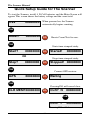
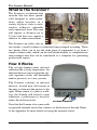
1
The Scanner
Passive Infrared People Counter
JAMAR
Technologies, Inc.
User’s Manual
i
The Scanner Manual
LIMITED WARRANTY
JAMAR Technologies, Inc. warrants The Scanner against defects in material and
workmanship for a period of one (1) year limited warranty on parts and labor from the
date of purchase. For information on extended warranty call 1-800-776-0940.
JAMAR Technologies, Inc. warrants each new instrument manufactured by the
company to be free from defective material and workmanship and agrees to remedy
any such defect. At its option, it may furnish a new part in exchange for any part
of any instrument of its manufacture which, under normal installation, use and
service discloses such defect. The instrument must be returned to our factory or
authorized service agent intact, for examination, with all transportation charges
prepaid.
This warranty does not extend to any products which have been subject to misuse,
neglect, accident, vandalism or incorrect wiring not our own. This warranty does
not extend to water damage caused by improper installation in disregard of the
instructions furnished by us. This warranty does not extend to products which have
been repaired or altered outside our factory or authorized service agent.
In no event shall JAMAR Technologies, Inc. be liable for any damages arising from
the use of this product including damages arising from the loss of information.
This warranty is in lieu of all other warranties expressed or implied and no
representative or person is authorized to assume for us any other liability in
connection with the sale or use of our products.
JAMAR Technologies, Inc. reserves the right to make improvements on the product
and/or specifications at any time without notice.
Questions concerning this warranty or any JAMAR Technologies, Inc. product
should be directed by mail or telephone to:
JAMAR Technologies, Inc.
1500 Industry Road, Suite C
Hatfield, PA 19440
215-361-2244
COPYRIGHT NOTICE
This manual is copyrighted. All rights are reserved. This document may not
be, in whole or part, photocopied, reproduced, translated, or reduced to any
electronic medium or machine readable form without prior consent, in writing, from JAMAR Technologies, Inc.
Copyright 2008 by JAMAR Technologies, Inc.
This device complies with Part 15 of the FCC Rules. Operation is subject to the following two
conditions: (1) this device may not cause harmful interference, and (2) this device must accept any
interference received, including interference that may cause undesired operation.
ii
If you have any questions about the use of The Scanner, please call the
following number:
215-361-2244
Monday - Friday 8:00 AM to 5:00 PM Eastern time
You may also contact us by e-mail at:
[email protected]
Address any correspondence to:
JAMAR Technologies, Inc.
1500 Industry Road, Suite C
Hatfield, PA 19440
Volume 1.16 July 2008
iii
The Scanner Manual
Table of Contents
Technical Support
.................................................................. iii
Initial Setup Guide for The Scanner ............................................................... v
Quick Setup Guide for The Scanner .............................................................. vi
Chapter 1 - Using The Scanner ................................................................ 1-1
What is The Scanner?
................................................................ 1-2
How it Works
................................................................ 1-2
Setting Up The Scanner
................................................................ 1-3
Main Screen
................................................................ 1-4
Selecting Options
................................................................ 1-5
Reset Screen
................................................................ 1-5
Start Time-stamped Study Screen ..................................................... 1-6
GPS Screen
................................................................ 1-7
Clear Memory Screen
................................................................ 1-8
Uploading Information to the Scanner ..................................................... 1-9
Downloading the Scanner with JRead .................................................... 1-12
Chapter 2 - Using the JPDA Software.......................................................... 2-1
Introduction to JPDA
................................................................ 2-2
Installing JPDA
................................................................ 2-3
Installing JRead
................................................................ 2-4
Getting Started with JPDA
................................................................ 2-3
Main Menu
................................................................ 2-3
Preferences Screen
................................................................ 2-4
Setup Screen
................................................................ 2-5
Status Screen
................................................................ 2-7
Ext. IR Screen
................................................................ 2-8
Retrieving Data from the Scanner .......................................................... 2-10
View Downloaded Files
.............................................................. 2-13
Transferring Data from JPDA with JRead .............................................. 2-14
Chapter 3 - Installing The Scanner .............................................................. 3-1
Installing the Mounting Bracket ............................................................... 3-2
Installing the Scanner in the Field ............................................................ 3-4
What Makes for a Good Location?........................................................... 3-4
Chapter 4 - Battery Care
Chapter 5 - Troubleshooting
................................................................ 4-1
................................................................ 5-1
Appendix
...............................................................A-1
Appendix #1 - Optional External Sensor................................................. A-2
Appendix #2 - Installing the Software ..................................................... A-6
Specifications
...............................................................A-8
iv
Initial Setup Guide
for The Scanner
Step 1
Remove the faceplate of the Scanner and install the batteries. This will
provide power.
Step 2
At this point, if you are only interested in recording overall totals, you can
proceed to installing the Scanner in the field, as discussed in Step 4. Overall
totals can be read directly off the display of the Scanner. If, however, you
would like to use some of the other options the Scanner has, like storing
GPS coordinates or starting a time-stamped study, go to Step 3.
Step 3
Familiarize yourself with the JPDA and JRead software, which is covered
in Chapters 1& 2 of this manual. These programs can be used to configure
the settings of the Scanner. These settings include the time and date, which
you should set for your location if you will be doing time-stamped studies.
JPDA can also be used to start & stop studies, and retrieve data from the
Scanner.
Step 4
Install the Scanner in the field. Refer to Chapter 3 for information on how
to pick and good location and how to physically install the Scanner.
Step 5
Start a new study using either the JPDA software or the programming guide
listed on the next page.
v
The Scanner Manual
Quick Setup Guide for The Scanner
To start the Scanner, install 4 D-Cell batteries and the Main Screen will
appear. This screen shows the battery voltage and the count total.
5.8V
00000000
When powered on, the Scanner
automatically begins counting.
TAB
Reset?
00000000
DO
Resets Count Total to zero.
TAB
Starts time-stamped study.
Start?
00000000
DO
OR
Stop?
00000000
Started!
00000000
Stops time-stamped study.
DO
Stopped! 00000000
TAB
Connect GPS receiver.
GPS
00000000
DO
Waiting
TAB
Pressing DO will cancel clear.
CLR MEM?00000000
DO
CLR? N
00000000
TAB
CLR? Y
00000000
Pressing DO will clear memory.
vi
Chapter 1 — Using The Scanner
Chapter 1
Using
The Scanner
1-1
The Scanner Manual
What is The Scanner?
The Scanner is an infrared data
recorder that has been specifically designed to count pedestrians and/or bicyclists in a
variety of places, such as trails,
outdoor walkways, sidewalks
and commercial areas. This unit
will register at distances up to
35 feet and does not require a
reflector or other external unit.
The Scanner can collect data in
two modes: overall volume or individual time-stamped recording. These
two modes allow you to use the same piece of equipment to go from a
simple volume count, which can be read off the display, to comprehensive
time-stamped data that can be transferred to a computer for generating
professional reports.
How It Works
The average human emits infrared
radiation due to body temperature. An
infrared detector can recognize the specific signature of this and determine
when a person is, or is not, present.
The Scanner contains an infrared
detector, located near the bottom of
the unit, as shown in the picture to the
right. When aimed at a path or walkway, the Scanner will record a count
whenever a pedestrian or bicyclist
enters the detection zone.
Infrared Detector
Note that the Scanner also comes with
an optional external sensor that connects to the bottom of the unit. Refer
to the Appendix for more details on using the external sensor.
1-2
Chapter 1 — Using The Scanner
Setting Up The Scanner
To begin using the Scanner, unscrew the two screws from the front of the
Scanner and lift off the front cover. Inside you will see the control panel
for the unit, along with the battery compartment.
With Front Cover
With Front Cover Removed
Control Panel
The Scanner is powered by four D-Cell Alkaline batteries, which are
included with the unit when it is shipped.
IMPORTANT: When you are ready to begin using the Scanner, install
the batteries following the polarity guidelines on the battery bracket.
The batteries should be removed if the unit is not going to be used for
an extended period of time.
Once the batteries are fully connected in the unit, the Main Screen of the
Scanner will appear.
1-3
The Scanner Manual
Main Screen
A 16-character LCD display, located in the middle of the Scanner's control
panel is used to display the current options and status. NOTE: The display
of the Scanner has a power-saving feature that turns off the screen if the
unit has not been disturbed for several minutes. To bring the display back
up, simply hit either the TAB or DO key.
Once power is provided to the Scanner, the Main Screen appears.
5.9V
00000000
This screen shows the battery voltage on the left side of the display, which
allows you to monitor the battery status. Generally, fresh batteries should
register at 5.8 to 6.0 VDC. Batteries should be replaced when this voltage
falls to around 4.5 to 5.0. The unit will stop recording data once the voltage
falls to approximately 4.0 volts.
Depending upon use and temperature where the unit is installed, the batteries
may last for more than six months before they need to be replaced. Refer to
Chapter 4 Battery Care for more information on battery maintenance.
When the Scanner is powered on, it begins recording counts, which are
displayed on the right side of the Main Screen. At this point, if you are
only interested in recording overall totals, you can proceed to installing the
Scanner in the field, as discussed in chapter 3. If, however, you would like to
use some of the other options the Scanner has, like storing GPS coordinates
or starting a time-stamped study, read on.
The remainder of this chapter covers, in a tutorial style, some of the additional options you have in setting up the Scanner using the control panel.
Note that you can also perform these functions remotely using the JPDA
software, which is discussed in Chapter 2.
1-4
Chapter 1 — Using The Scanner
Selecting Options
There are two buttons on the control panel of the Scanner that are used to
navigate through the various screens and select options. The black TAB key
is used for navigation, while the red DO key is used to select an option.
With the Main Screen visible (remember, if the display goes into power
saving mode, press either key to bring it back up), go ahead and press the
TAB key. Notice that the screen changes to show Reset? on the left side of
the display rather than the battery voltage. Your current count total is still
visible on the right side.
Press TAB again, and the screen changes to show Start?. Press TAB again
and it shows GPS. Press TAB again and it shows CLR MEM?. Press TAB
on more time, at it takes you back to the Main Screen, which shows the
current battery voltage.
The four screens we just went through are the ones used to select various
options in the Scanner. Press the TAB button repeatedly and notice that you
loop through these four screens, always coming back to the Main Screen.
Now we'll take a look at what we can do with the four option screens.
Reset Screen
When at the Main Screen, press the TAB key once and the Reset Screen
will appear.
Reset?
00000000
This screen is used to reset the current count total visible on the right side of
the display. Press the DO key while on this screen and notice that the count
total resets to zero and you are taken back to the Main Screen.
Note that if you are in the Reset Screen and decide that you do not want to
reset the count total, simply wait a few second without doing anything and
the Scanner will return to the Main Screen on its own. Alternatively, you
can press the TAB key until you return to the Main Screen.
Note also that selecting the Reset option will also stop any current timestamped study being done, and immediately start a new one. We will find
out more about time-stamped studies in the next section.
1-5
The Scanner Manual
Start Time-stamped Study Screen
When at the Main Screen, press the TAB key twice and the Start Timestamped Study Screen will appear.
Start?
00000000
As we have learned, when you power on the Scanner it begins counting and
shows the count on the right side of the display. This information is useful
if you want an overall count of pedestrian volumes. However, what if you
want more detailed information, such as specific information on when the
volumes are occurring or what direction people are travelling? That's where
the Time-stamped study comes in.
The Scanner has the ability to record and store a time stamp of every individual count it records. These time stamps are stored in memory and can later
be downloaded into the JPDA or JRead software for analysis and reporting.
(These programs are discussed a little later in this manual.) The Scanner's
internal memory is 256 KB, which will hold approximately 80,000 time
stamps before becoming full.
Note: When in Time-stamped mode, the Scanner not only records when a
count occurs, but the direction of travel. Direction one is recorded as left to
right movement, while direction two is recorded as right to left movement
(from the Scanner's point of view).
Press the DO key while on the Start? screen and the display will change
to the one shown below.
Started!
00000000
The overall count total shown on the display will reset to zero, and the unit
will begin storing the time-stamped data internally. The Scanner will then
return to the Main Screen.
Note: For your time-stamped study to be accurate, it is important that the
Scanner have the correct time stored in its memory. Refer to the Uploading Information to the Scanner section on page 1-9 for more information
on this.
1-6
Chapter 1 — Using The Scanner
From the Main Screen, hit the TAB key twice and notice that the Start?
option has now been replaced by Stop?. This screen will appear if you currently have a time-stamped study in progress and it gives you the option
to stop that study.
Stop?
00000000
Hit the TAB key a few more times and notice that it will loop you through
only two options: Reset? and Stop?. When a time-stamped study is in progress, these are the only two options of the original four that are available
for selection. You must end the time-stamped study to access the additional
options.
Tab back to Stop? showing on the display and press the DO key. The display
will change to the one shown below.
Stopped! 00000000
At this point, the time-stamped study is stopped and stored in memory. A
little later on we will see how this study can be downloaded and how it can
be cleared from memory. After a few seconds, the Scanner will reset itself
to the Main Screen.
GPS Screen
When at the Main Screen, press the TAB key three times and the GPS
Screen will appear.
GPS
00000000
GPS coordinates can be loaded into the Scanner by connecting a handheld
GPS receiver to the comm port on the Scanner's control panel.
Note: The GPS receiver must be set to transmit one of the following NMEA
messages at 4800 baud: GPRMC, GPGLL or GPGGA.
1-7
The Scanner Manual
Press the DO key and the display will change to the one shown below.
Waiting
Plug the GPS receiver into the Scanner's comm port and, if the receiver
is configured properly, the Scanner will receive the coordinates and begin
showing them on the display, alternating between showing latitude and
longitude. Press the DO key to accept the coordinates and the Scanner will
return to the Main Screen. Note that if you press the DO key on the Waiting
screen when no GPS receiver is connected, the Scanner will cancel out to
the Main Screen.
Clear Memory Screen
When at the Main Screen, press the TAB key four times and the Clear
Memory Screen will appear.
CLR MEM?00000000
The Clear Memory option can be used to delete time-stamped studies that
have been stored in memory. However, to prevent studies from being accidently deleted, you are required to confirm that you want to clear the
memory. Press the DO key and the screen shown below will appear.
CLR? N
00000000
On this screen, the 'N' means No, do not clear memory. If you press DO
at this point, The Scanner will cancel out of the memory clear process and
return to the Main Screen. Press TAB instead, and the screen shown below
will appear.
CLR? Y
00000000
On this screen, the 'Y' means Yes, do clear memory. If you press DO at this
point, the Scanner will clear all stored time-stamp studies from memory
and return to the Main Screen.
1-8
Chapter 1 — Using The Scanner
Uploading Information to the Scanner
When in Time-stamped study mode, it is important that the Scanner have
the correct time stored in its memory. The time, along with several other
pieces of information, can be uploaded into the Scanner using the free JRead
software, which can be downloaded from the Software Downloads section
of the JAMAR web site, www.jamartech.com.
Note that the upload can also be done using a PDA running the free JPDA
software. This can be done through either connecting to the Scanner's
comm port or wirelessly using the Scanner's Bluetooth wireless connection. If you plan to use a PDA with your Scanner, skip to the next
chapter now.
After downloading the installation file for JRead, double click on it and
follow the on-screen instructions to install the program on your computer.
Once the program is installed, it can be used to upload information into the
Scanner using the comm (serial) port of the Scanner and a serial cable, such
as the JAMAR universal cable. (It is not required that a JAMAR cable be
used. Any compatible RS-232 serial cable will work.)
To prepare to upload your information to the Scanner, connect the serial
cable to a serial port on your computer (or a USB port using a USB to
Serial adapter). Most serial ports are a 9 pin plug, and there may be more
than one on the computer. The ports may be labeled on the computer itself
with COM 1 listed as 1 or A and COM 2 listed as 2 or B. Refer to chapter
5, Troubleshooting, for tips on avoiding problems when using a computer's
serial port, or what to do if your computer does not have a serial port.
On the Scanner itself, you must have the display visible to upload information. If the unit is in power saving mode and the display is not visible, hit
either the TAB or DO key to bring it back up. Once the display is visible,
start the JRead software.
Once the program is open, use the Comm Ports box at the top left to select
the comm port that the Scanner is connected to on your computer. The Baud
Rate field below this can be used to select the download speed. For most
computers, the top setting of 115200 can be used.
1-9
The Scanner Manual
Once the comm port and baud rate are set, click on the Upload Settings to
Counter tab and then click the Read Settings button. A list of the various
settings that can be uploaded is then displayed, as shown here.
JRead can be used with several different types of JAMAR equipment, so only
the options in the program that apply to the Scanner are enabled – settings
that do not apply are disabled when connected to a Scanner. The settings
we'll use are Time, Date, Site ID and Site Code.
The Time and Date listings in JRead can either be manually typed in or
read from your computer’s clock. To enter a time or date manually, be sure
the Use PC Time/Date box is unchecked. If you place a check in this box,
JRead will use the computer’s clock for the time and date.
The Date Format field can be used to control how the date is listed in the
Scanner. The options are USA (month/day/year) or World (day/month/
year).
If you want to change the time, date or date format in the Scanner, be sure
to check the Set Time/Date box. If this box is not checked, JRead will ignore
the time, date and format settings when uploading to the Scanner.
1-10
Chapter 1 — Using The Scanner
The Site Code and Station ID fields are descriptions that can be saved with
the Time-stamped study to help you identify the location of the data when
processing it. You can enter any information in these fields that will help you
identify the count. Note that you are not required to use these fields for your
studies, they are provided for those users who would like to use them.
Once you have the Date and Time set the way you want, and have entered
any Site information, you are ready to upload this information. First, make
sure the display of the Scanner is visible, then click the Upload Settings
button in JRead. The Download Status field located directly above the tab
will show the status of the upload and let you know when it is complete.
Note that several other settings specific to the Scanner can be uploaded
using the JRead program. These are in the field on the right side of the tab
labelled Scanner and can control some of the more advanced options of
the Scanner.
Use Main IR: This turns on the main IR sensor, known as sensor 1. In most
units, this is the sensor installed internally in the scanner housing.
Use IR 2: Turns on the optional main external sensor, known as sensor 2.
Use IR 3: Turns on the secondary external sensor, known as sensor 3.
Invert Main IR: This swaps the direction information collected from the
Main IR sensor.
Invert IR 2: Same as above for sensor 2.
Invert IR 3: Same as above for sensor 3.
(The Invert options allow you to change the recording direction of a sensor.
It allows you to adjust for installation issues that could change the directions, such as moving the Scanner to the opposite side of the trail being
monitored.)
Use DT Tot: This enables the Dead Time setting for the recording of the
total shown on the Scanner's display.
Use DT TS: This enables the Dead Time setting for the recording of timestamped data.
Combine DT: When multiple sensors are being used, this setting configures
the Scanner to use a single DT for the recording of data, both for the unit's
display and for time-stamped data.
(Under normal use, the Scanner does not require a Dead Time. However,
when multiple sensors are being used with an overlapping detection zone,
using a DT may be desirable.
1-11
The Scanner Manual
Combine TS: When multiple sensors are being used, this setting configures
the Scanner to have all enabled sensors report as a single sensor, sensor 1.
This is useful for situations where a larger detection zone is desired. If the
detection zones from the sensors overlap, it may be necessary to set the
Combine DT option.
Downloading the Scanner with JRead
Time-stamped studies done with the Scanner can be downloaded and exported using the JRead software.
Note that time-stamped data in the Scanner can also be retrieved using
the free PDA-based JPDA software. This can be done through either
connecting to the Scanner's comm port or wirelessly using the Scanner's
Bluetooth wireless connection. If you plan to use a PDA to retrieve your
data, skip to the next chapter now.
The download of data is done through the same comm port of the Scanner
used to upload settings, as discussed in the previous section. For connection
information, refer back to that section.
Note that you cannot download studies that are currently in progress.
If you have a study in progress that you would like to download, you must
end the study by pressing TAB until Stop? is visible, then pressing DO.
On the Scanner itself, you must have the display visible to download data. If
the unit is in power saving mode and the display is not visible, hit either the
TAB or DO key to bring it back up. Once the display is visible, the download
will transfer all time-stamped studies currently stored in memory.
To start the download, start the JRead software then click on the Download All Counter Data button at the top. The Download Status field will
then change to show you the status of the download. Once the download
is complete, as list of the files that have been transferred will appear in the
Recently Downloaded Files field.
The Recently Downloaded Files list has all the studies that have been downloaded from the Scanner, with the currently selected study highlighted in
black. All other studies will be colored light red, indicating that they have
not yet been processed. Note that once a study has been processed from the
list, it will be colored green.
1-12
Chapter 1 — Using The Scanner
The buttons along the bottom of the screen list several options for how
to process the studies, including Export Excel, Export ASCII and Process
with TRAXPro. (Note that the Process with TRAXPro option is mainly
for use with data from a TRAX traffic data recorder and not data from a
Scanner.)
Export to Excel or ASCII
The Export Excel and Export ASCII selections both work in the same manner. The only difference is that one provides an Excel file while the other
provides a comma delimited text file.
To export a file into either of these formats, the first thing you need to do
is select the interval length for the data. This is done by using the Interval
Length field on the left. The options are: Time Stamp, 1 Minute, 5 Minutes,
10 Minutes, 15 Minutes, 30 Minutes and 60 Minutes.
1-13
The Scanner Manual
The Time Stamp option produces a file listing the individual time stamp (to
the second) of every recording in the study. The other options will group
the data into the interval time selected. Below are examples of the Excel
exported time stamp and 15 minute interval formats.
In the Time Stamp format, each recording in the study is listed with its
time stamp and the direction in which it was recorded. For example, in the
Time Stamp study shown above, the first recording occurred at 9:00:06 AM,
traveling in the first direction.
Once you have selected the Interval Length you want, highlight the file
you want to export by clicking on it, then click either the Export Excel or
Export ASCII button. You will be prompted to assign the file a name and
select a folder to save it in.
Once you click Save, a window will appear listing the path where the file
was created. This window allows you to either directly open the newly
created file with Excel or Notepad (depending on if Excel or ASCII export
was used) or open the folder where the file was saved.
Note that downloaded studies will remain in the memory of the Scanner
until they are cleared. Refer to page 1-8 for information on how to clear the
memory. Important: Do not clear the memory of the Scanner until you are
certain that the data has been successfully downloaded to you computer.
1-14
Selectively Downloading Data with JRead
While we just discussed the steps for retrieving all the data you have stored
in your Scanner using JRead, another option that you have is to selectively
choose which data in the Scanner's memory to download.
This is done using the Select Counter Files to Download tab near the top
of the screen. Once your Scanner is connected, click the Counter File
List button and a list of the files in the Scanner will appear in this tab.
The checkboxes to the far right can be used to select the files you want to
retrieve, then the Download Selected button can be used to transfer them
to your computer. The files you selected will then appear in the Recently
Downloaded Files box and can be exported.
1-15
The Scanner Manual
1-16
Chapter 2 — Using the JPDA Software
Chapter 2
Using the
JPDA
Software
2-1
The Scanner Manual
Introduction to JPDA
JPDA is free interface software for the Scanner that runs on a Personal
Digital Assistant (PDA). This program is designed to make setup of the
Scanner, and retrieval of data from it, a more convenient process. Data that
has been retrieved with JPDA can be transferred to a desktop computer
using the free JRead software. JRead allows the data to be processed and
output to a TRAXPro or Excel file, along with other formats.
Supported PDAs
JPDA currently runs on Pocket PC based PDAs. It does not currently support Palm PDAs. In general, almost any Pocket PC version PDA made
in the last couple of years should work. There are several companies that
sell Pocket PC PDAs, with the most popular being those made by Hewlett
Packard (the Ipaq series). Regardless of brand, Pocket PC PDAs look very
much the same since they run the same operating system.
Choosing which PDA is right for you can be complicated because there
are many different features available. However, JPDA will be much more
useful if the PDA you use has Bluetooth wireless capability. With JPDA
software running on a PDA equipped with Bluetooth wireless capability, it
is possible to setup and retrieve data from the Scanner without ever having
to remove it from the field.
Software Updates and Support
Updated versions of JAMAR software are released periodically and are
posted on the JAMAR web site. Users of JPDA may download updates
to the program to make sure they always have the latest version of the
software on their PDA. To download the latest version of JPDA, go to
www.jamartech.com and then select Downloads from the list of options.
If you encounter any problems while using the program, or have any questions on specific operations, refer first to this manual. For up to the minute
information on all known issues with the program, refer to the JPDA support
web page at: www.jamartech.com/JPDAsupport.html.
Installing the Software
It is a simple process to install both the JPDA and JRead programs. If you
have not already installed these programs, do so now using the instructions
found in the Appendix.
2-2
Chapter 2 — Using the JPDA Software
Getting Started with JPDA
Once you have installed JPDA and JRead you are ready to start using JPDA.
Tap on the JPDA icon in the Programs menu. This loads the Main screen.
Main Screen
The Main Screen is arguably the most important screen in the software.
Nearly all of the software's functions can be accessed from this screen. The
main options on this screen are:
View Downloaded Files - View a list of
downloaded files.
Read -Retrieve data from the Scanner.
Prefs - Set Preferences for JPDA.
Setup - Upload settings to the Scanner.
Once you initiate a task from the Main
screen, you will be presented with another screen specific to that particular
operation, such as reading the Scanner.
When the task is completed, you will
return to the Main screen.
If this is your first time using JPDA (if
you're reading this, it probably is), then
you will need to provide JPDA with the proper Preference Settings. Tap
the Prefs button at the bottom of the screen. This opens the Preference
screen.
2-3
The Scanner Manual
Preferences Screen
The Preferences screen allows you to adjust the major parameters of JPDA.
You can select the port number and baud rate that will be used to communicate with the data recorder by selecting the desired option from each
drop-down box.
Set the Comm Port to 1 if you'll be
connecting through your PDA's cradle
port connector.
If you'll be connecting via wireless
Bluetooth, select the outbound bluetooth
port of the PDA. This is typically the
second port listed with the (BT) suffix
in the list of ports.
If you'll be connecting using an adapter
plugged into the CF slot, select the port
option listed with the (CF) suffix.
Set the Baud Rate as desired. This
controls the speed of the data transfer.
The higher the number, the faster the transfer. Some older PDA's may not
be able to handle baud rates over 19200 baud. For now, select 57,600 as
the baud rate.
JPDA allows you to use a GPS receiver to store the exact location of the
study along with the data, if you have a GPS receiver plugged into your
PDA. Enable this if you are using GPS, otherwise leave it set to 'No'.
Now JPDA's settings are tailored to your equipment and the program is
ready to be put to work for you. Tap Done to return to the Main screen.
2-4
Chapter 2 — Using the JPDA Software
Setup Screen
JPDA can be used to configure a number of settings in the Scanner. First,
select Scanner from the dropdown list below the big Read button on the
Main screen. Next, tap the Setup button and the Setup screen will appear.
If you are planning to do a time-stamped
study with the Scanner, this screen allows you to load information related to
that study into the Scanner. To do this,
you will need to connect to the Scanner
using either a wireless Bluetooth connection or by plugging into the comm
port on the Scanner. This tutorial covers
using a wireless connection; however,
the steps are essentially the same using
a hard wire connection.
When the Setup screen comes up, it
shows the time and date in the Set
Clock field at the top. These are read in
directly from the time and date set on
the PDA. If they are not correct, close JPDA and reset the time and date
on the PDA itself.
If the Set Clock checkbox is checked, then JPDA will set this time and date
into the Scanner when you perform the upload.
Below the clock field are the Site Code and Station ID fields. Whatever
you put in here will show up in the corresponding fields when the study is
processed, and can be printed on reports with the data. You can fill in the
fields however you wish.
Note that it takes a little bit of practice to enter text and numbers into a
PDA. The easy way to do it is to use the popup keyboard and tap the letters
and numbers to enter the information. You can also learn to enter letters
and numbers using the handwriting recognition option that is part of all
PDAs. With a little practice you can learn to enter the letters and numbers
much faster than with the popup keyboard.
2-5
The Scanner Manual
Once you have the information entered
that you want, tap the Upload Info
button to begin the transfer to the data
recorder.
If you are using Bluetooth, and the PDA
is able to find an available Bluetoothequipped device nearby, you'll see a
screen like the one shown to the left.
This screen allows you to select the
Bluetooth device you want to connect
to. Each Bluetooth-equipped data recorder is listed with its serial number,
so if you have multiple devices you can
choose a specific one.
Tap on the Scanner you want and the setup info will be transferred. You
will then be returned to the Setup screen.
If you ever what to check what information is currently stored in your
Scanner, the Get Info button basically does the reverse of the Upload Info
button. Tap Get Info and JPDA will read in the Site Code, Station ID and
GPS info that is currently stored in the Scanner.
2-6
Chapter 2 — Using the JPDA Software
Status Screen
Another option on the Setup screen is
Status. Tap this button and you'll be
taken to the Status screen, as shown
to the left.
The Status screen allows you to control
a variety of commands for the Scanner, including starting and stopping
a time-stamped study (Start and Stop
buttons), resetting the total on the unit's
display (Reset button), checking to see
a list of time-stamped studies stored in
memory (Dir button) and deleting all
studies from the memory of the recorder
(Clear button).
In addition, this screen can be used to check the current volume total from
the Scanner's display.
Tap the green Status button at the lower left of the display to check the current status of the Scanner. If you are using Bluetooth, you have to select the
device you want, as described in the previous section.
If JPDA is able to connect to the Scanner, it will display the unit's status, as
shown to the left.
The top line displays the unit type. This
is followed by the firmware version.
The next line displays the Scanner's
serial number, which is followed by
the current battery voltage. The fifth
line displays the Time and Date, which
is followed by any Site ID and Station
ID information that has been uploaded
into the unit. The eighth and ninth lines
list any GPS coordinates that have been
stored. The next line lists whether the
2-7
The Scanner Manual
Scanner is recording a time-stamped count or is idle. The final line list the
current total on the Scanner's display.
Now that we've checked the status of the Scanner, we can have it start a
new time-stamped study for later downloading. To do this, we tap the Start
button to begin a new time-stamped count. A confirmation screen then tells
us the count has started.
Ext. IR Screen
Another option on the Setup screen is
Ext. IR. Tap this button and you'll be
taken to the Setup IR screen, as shown
to the left. Several other settings specific
to the Scanner can be uploaded by using
this screen.
The Dead Time setting allows you to
enter a period of time, in milliseconds,
that the Scanner will wait after it records
a count before it will accept another one.
This setting can help to prevent 'doublecounting' of individual people. The
default value is 250 ms. If the Scanner
appears to be double counting, increase this value. If the Scanner appears
to be missing people that are close together and undercounting, decrease
this value.
Additional settings that can be turned on or off are:
Use Main IR: This turns on the main IR sensor, known as sensor 1. In most
units, this is the sensor installed internally in the scanner housing.
Use IR 2: Turns on the optional main external sensor, known as sensor 2.
Some models of Scanners are equipped with external sensors that plug into
the bottom of the unit.
Use IR 3: Turns on the secondary external sensor, known as sensor 3.
Reverse Main IR: This swaps the direction information collected from
the Main IR sensor.
Reverse IR 2: Same as above for sensor 2.
Reverse IR 3: Same as above for sensor 3.
2-8
Chapter 2 — Using the JPDA Software
(The Reverse options allow you to change the recording direction of a
sensor. It allows you to adjust for installation issues that could change
the directions, such as moving the Scanner to the opposite side of the trail
being monitored.)
Use Combined Dead Time: When multiple sensors are being used, this
setting configures the Scanner to use a single DT for the recording of data,
both for the unit's display and for time-stamped data.
(Under normal use, the Scanner does not require a Dead Time. However,
when multiple sensors are being used with an overlapping detection zone,
using a DT may be desirable.
Combine Sensors: When multiple sensors are being used, this setting
configures the Scanner to have all enabled sensors report as a single sensor, sensor 1. This is useful for situations where a larger detection zone is
desired. If the detection zones from the sensors overlap, it may be necessary
to set the Use Combined Dead Time option described above.
Enable Buzzer: This setting will turn on a buzzer when a sensor is activated.
2-9
The Scanner Manual
Retrieving Data from the Scanner
The main purpose of JPDA is to allow you to retrieve data from a JAMAR
data recorder, like the Scanner. There are many different types of JAMAR
equipment that can be used with JPDA, so first use the dropdown menu just
below the Read button to select the Scanner. Once this has been selected,
tap the big Read button.
The Read Counter Data screen is fairly
easy to use. There's just one option on
the screen to deal with: whether you
want to read all the studies in your
Scanner, or just the new studies in the
Scanner.
The Scanner can have multiple studies
from different times stored in memory.
JPDA is able to recognize which of these
studies have already been downloaded
and which are new. The All/New option
lets you take advantage of this.
When you download your data, if you
only want the new studies done since you last downloaded, you should select
the New option. However, if, for whatever reason, you want to download all
the studies stored in memory (both old and new), select the All option.
The default option is to download just New studies. We recommend leaving
this selected unless you have a specific reason to change it to All.
Note: You cannot download studies that are currently in progress. If
you have a study in progress that you would like to download, you must
end the study before attempting to download.
Once you have the option you want, you are ready to read your data. If you
are using a hardwired connection (a cable connected from the PDA to the
Scanner), make sure the cable is properly connected, then press Go. If you
are using a wireless Bluetooth connection (no cable connected to the data
recorder), just press Go.
2-10
Chapter 2 — Using the JPDA Software
The rest of this tutorial covers using a wireless connection; however, the
steps are essentially the same using a hard wire connection.
Reading Data with Wireless Bluetooth
If you are using a wireless Bluetooth
connection to connect to the Scanner,
when you tap the Go button JPDA will
attempt to find all the nearby Bluetooth
devices. You'll then see a screen similar
to the one to the left.
This screen allows you to select the
Bluetooth device you want to connect
to. Each Scanner is listed with its serial
number, so if you have multiple devices
you can choose a specific one.
Tap the device you want to connect to
and JPDA will attempt to connect.
If JPDA is able to connect, it will
check to see if the Scanner currently
has a study in progress. If there is a
study in progress, the screen shown
to the left will appear, with JPDA asking if you want to stop it so it can be
downloaded.
If you select No, the study currently
running will continue to run and JPDA
will attempt to download any previous
studies stored in memory. If you select
Yes, JPDA will then ask you if you want
to start a new study once the currently
running one is stopped.
Note: These options are very useful if you are continuously collecting data
at a location and periodically retrieving the data from the Scanner.
2-11
The Scanner Manual
Once JPDA begins retrieving data from the Scanner, the screen will change
to show the message 'Downloading Block" followed by a number representing the block of data that is being read in. (Each block represents approximately 1000 characters.) JPDA doesn't know how many blocks the counter
is going to send, it just processes each block until the counter is done.
Note that if JPDA is not able to connect, the screen will show an error that
the download has timed out. In this case, see the troubleshooting chapter
for issues to check.
Once the download is complete, the View Downloaded Files screen will
appear.
2-12
Chapter 2 — Using the JPDA Software
View Downloaded Files
When you have finished downloading data from your Scanner, the View
Downloaded Files screen appears, as
shown to the left.
Note that you can also access this information at any time from the Main
screen by tapping the View Downloaded
Files button.
This screen allows you to see what
data files are currently stored in JPDA.
The serial number of the data recorder
from which the file was read is listed,
followed by any Site Code and Station
ID that were stored with the file.
Note that this screen can be used if you want to delete any of the data files
stored in the JPDA. To delete an individual file, highlight it by tapping
on it, then tap the Delete button. To delete all the files, tap the Delete All
button.
If you want to see more details of a particular file, highlight the file by tapping on it, then tap the Header Info button.
This screen, shown to the left, provides
additional information about the file you
selected.
The information provided includes the
date and time the file was read into
JPDA, the type of data recorder it was
from, the serial number of the data recorder, and more.
Tap OK when you are done looking at
the file details and you'll be returned to
the list of downloaded files. Tap Close
to return to the Main screen.
2-13
The Scanner Manual
Transferring Data from JPDA with JRead
Once you have read the data from your Scanner into JPDA, you’ll need to
transfer that data to your laptop or desktop computer for data processing.
This transfer is accomplished using the JRead program.
JRead was included with your JPDA CD. If you have not already installed
the program, do so now.
Once JRead is installed, plug your PDA into your computer and let them
connect via ActiveSync.
Below is the screen you see when you run the JRead software.
Near the top of the screen are two buttons that provide different ways of
getting data into JRead. The Download All Counter Data button can be
used if you want to download the Scanner directly into the program (refer
to the page 1-12 for more details on this), while the Download All PDA
Data button can be used to retrieve data your data from JPDA.
2-14
Chapter 2 — Using the JPDA Software
Note that the Download All PDA Data button will be colored green and
enabled if the program sees an ActiveSync connection from your computer
to a PDA. If JRead does not see this connection, the button will be greyed
out and disabled. (The connection status of the PDA can also be seen in the
box at the bottom left of the program.)
Click the Download All PDA Data button when you are ready. The software
connects to the PDA using the Active Sync software and copies a temporary
file, containing all the data in JPDA, from the PDA into a folder on your
computer. The JRead screen will then update to show the list of files that
you have transferred, as shown below.
The list of files is shown is two places - the top box under the Select PDA
Files to Download tab (we'll discuss this shortly) and the bottom box under
Recently Downloaded Files.
The Recently Downloaded Files list has all the studies that have been transferred from JPDA, with the currently selected study highlighted in black.
All other studies will be colored light red, indicating that they have not yet
2-15
The Scanner Manual
been processed. Note that once a study has been processed from the list, it
will be colored green.
The buttons along the bottom of the screen list several options for how
to process the studies, including Export Excel, Export ASCII and Process
with TRAXPro. (Note that the Process with TRAXPro option is mainly
for use with data from a TRAX traffic data recorder and not data from a
Scanner.)
Export to Excel or ASCII
The Export Excel and Export ASCII selections both work in the same manner. The only difference is that one provides an Excel file while the other
provides a comma delimited text file.
To export a file into either of these formats, the first thing you need to do
is select the interval length for the data. This is done by using the Interval
Length field on the left. The options are: Time Stamp, 1 Minute, 5 Minutes,
10 Minutes, 15 Minutes, 30 Minutes and 60 Minutes.
In the Time Stamp format, each recording in the study is listed with its
time stamp and the direction in which it was recorded. For example, in the
Time Stamp study shown above, the first recording occurred at 9:00:06 AM,
traveling in the first direction.
2-16
Once you have selected the Interval Length you want, highlight the file
you want to export by clicking on it, then click either the Export Excel or
Export ASCII button. You will be prompted to assign the file a name and
select a folder to save it in.
Once you click Save, a window will appear listing the path where the file
was created. This window allows you to either directly open the newly
created file with Excel or Notepad (depending on if Excel or ASCII export
was used) or open the folder where the file was saved.
Note that downloaded studies will remain in the memory of the Scanner
until they are cleared. Refer to page 1-8 for information on how to clear the
memory. Important: Do not clear the memory of the Scanner until you are
certain that the data has been successfully downloaded to you computer.
Selectively Retrieving Data from JPDA with JRead
While we just discussed the steps for retrieving all the data you have stored
in JPDA using JRead, another option that you have is to selectively choose
which JPDA data to retrieve and process.
This is done using the Select PDA Files to Download tab near the top of
the screen. Once your PDA is connected, click the PDA File List button
and a list of the files in the PDA will appear in this tab. The checkboxes
to the far right can be used to select the files you want to retrieve, then the
Download Selected button can be used to transfer them to your computer.
The files you selected will then appear in the Recently Downloaded Files
box and can be exported.
2-17
The Scanner Manual
2-18
Chapter 3 — Installing The Scanner
Chapter 3
Installing
The Scanner
3-1
The Scanner Manual
The Scanner is designed to be mounted to a tree or
pole. For ease of installation, we recommend using the
mounting bracket included with the Scanner's installation kit. This kit contains all the equipment needed to
install the Scanner in the field.
Installing the Mounting Bracket
The mounting bracket included with the Scanner is designed to help make
the installation of the unit as easy as possible. This bracket can be attached
to the back of The Scanner using the steps described below.
Insert a long screw through one of the screw holes in the front of The
Scanner. Using the screwdriver included with the kit, attached one of the L
clamps to the back of the unit, facing inward.
Repeat the process to attach the second L clamp to the back of the unit.
3-2
Chapter 3 — Installing The Scanner
Insert the long clamp between the L clamps and secure with four screws.
Run the installation cable through two of the holes on the mounting
bracket.
The Scanner is now ready to be taken into the field for final installation.
3-3
The Scanner Manual
Installing the Scanner in the Field
The Scanner is designed to be mounted to a tree or pole about 4 to 5 feet
from the ground. It should be set about 10 feet back from the path being
monitored, with the front of the Scanner facing the pathway. It should be
parallel to the path so that the infrared sensor is aimed directly across the
path. For best results, it should be aimed at a nearby tree or bush on the
other side of the path to limit the detection range.
What makes for a good location?
There are a few question you should ask when choosing a location to install the Scanner.
1. Is there anything on the opposite side of the pathway to limit the
detection range?
This is especially important in areas near roadways. If a passing vehicle
has its windows down, the Scanner will readily detect passengers. Also,
keep in mind that the detection area for the Scanner is a horizontal triangle
and increases with distance. For this reason, it is best to aim The Scanner
at a pine tree or a large bush.
3-4
Chapter 3 — Installing The Scanner
2. Is there anything stable enough to mount the Scanner on?
To record the most accurate data, the Scanner needs to be mounted so that
it will be stable in the wind. If the Scanner is swaying in the wind, it could
possibly double count some pedestrians who pass by. For this reason, it
is best to mount the Scanner on a tree with a large trunk, or on a pole or
building.
3. Is there anything at the location that will help hide the Scanner?
The less visible the Scanner is, the less likely it is to be vandalized. If you
are planning on mounting the Scanner to a tree, look for a tree with a large
trunk. A larger trunk will help hide the outline of the Scanner, as well as
be more stable in the wind. Mounting the Scanner where it will be concealed by a bush or tree branches will hide the Scanner very well, but may
require that the foliage be trimmed periodically to keep it from blocking
The Scanner. If the sensors at the bottom of The Scanner are blocked,
the unit will not work properly!
4. How easy will it be to reach the Scanner?
To retrieve the data, if you are not using a wireless connection (see Chapter
2), you will need to be able to remove the front panel and either read the
display or connect a serial cable. For convenience, you will want to be
able to access the unit easily. However, to deter vandals, you may want to
compromise in that area.
5. How easy will it be to locate the Scanner?
If you are going to check the Scanner periodically, you may have difficulty
locating the spot it was installed. This could be especially true if you are
returning in the early morning or evening while it is dark out. Make sure
that there are good landmarks that will help you return to the unit. A useful
tool for finding the Scanner again is a handheld GPS receiver. If you write
down the coordinates where the Scanner was installed, the GPS receiver
should help make sure you look in the right area.
6. How far does the Scanner need to record?
The Scanner will record data up to a maximum of 35 feet. We do not recommend that you attempt to record data beyond this distance.
Tip: Mounting the Scanner on a 45 degree angle to the trail will provide
more accurate data from people walking next to each other.
3-5
The Scanner Manual
Once you have selected the installation location, wrap the installation
cable around the pole or tree you have selected, pointing the Scanner toward the spot to be counted. Thread each loose end of the installation cable
through the cable clamp as shown in the picture below.
Pull the cable ends tight so that the Scanner is tight against the tree, then
tighten the nuts on the cable clamp using the installation kit's nut driver, as
shown in the figure below.
The Scanner is now installed and ready to begin recording data.
3-6
Chapter 4 — Battery Care
Chapter 4
Battery Care
4-1
The Scanner Manual
Battery Care
The Scanner is powered by four D-Cell batteries. Use of low power electronics in the Scanner makes it possible for the batteries to last for several
months, depending on use.
The main screen shows the current battery voltage. Fresh batteries should
read from 5.8 to 6.0 volts. Batteries should be replaced when this voltage
falls to around 4.5 to 5.0. The unit will stop recording data once the voltage
falls to approximately 4.0 volts.
The front compartment of the Scanner contains the battery holder. The batteries can easily be popped out and replaced. You should use high quality
alkaline batteries, which you can get at any convenience store.
The overall volume total shown on the main screen of the Scanner will reset
if the batteries are removed. However, any data collected in Time-stamped
mode will be retained in memory by an internal lithium battery even if the
D-cell batteries are removed. Just to be safe, however, we suggest that you
download the data in memory to your computer before you replace the batteries, then clear the memory after the new batteries are installed to reset
everything properly.
********IMPORTANT********
Be very careful to observe the proper polarity when installing new batteries. Prolonged use of the Scanner with incorrectly installed batteries
can cause batteries to burst, damaging the unit.
Do not mix old batteries with new batteries, or mix brands of batteries,
when replacing the batteries. This can cause batteries to burst, damaging
the unit.
We recommend that you keep track of when you have changed the batteries
in the Scanner, and establish a regular routine for changing them. This should
help to avoid having to change the batteries in the middle of a study.
4-2
Chapter 5 — Troubleshooting
Chapter 5
Trouble
shooting
5-1
The Scanner Manual
Troubleshooting
The following are some common questions/problems that can be encountered when using the Scanner. The possible answers that are stated with
them are not necessarily the only answer, but should be checked first before
contacting us. If you cannot find the answer to your problem/question, do
not hesitate to contact us. Contact information is listed on the first page of
this manual.
There is no display visible on the Scanner.
Check that the unit is not in its power-saving mode. The display automatically goes out when The Scanner has not been disturbed for several
minutes. To bring the display back up, hit the DO or TAB key.
The display on the Scanner will not come on.
The battery voltage may have gone too low to power the display. Replace
the batteries, then see if the display comes up. Note that this will reset the
total to zero on the Scanner's display.
The data is not being collected in the format desired.
When turned on, the Scanner collects overall volume data, which is shown
on the right side of the display. To start the time-stamped data collection
format, where each activation is stored in memory with a time stamp, press
the TAB key until Start? is displayed, then press the DO key.
The data produced is not accurate.
Check that the infrared port of the Scanner has not become blocked, which
will prevent it from recording data. Also check the installation used in the
field to be sure the Scanner is installed in such a way that it will not pick
up extraneous counts. Refer to page 3-4 for more tips to selecting a good
location.
GPS coordinates will not load from a GPS receiver.
Check that the GPS receiver has been configured to transmit in the format
required by The Scanner. The GPS receiver must be set to transmit one of
the following NMEA messages: GPRMC, GPGLL or GPGGA.
5-2
Chapter 5 — Troubleshooting
Cannot connect to the Scanner for upload or download.
First, check your connection between the Scanner and the computer. A
JAMAR universal cable should be plugged firmly into the comm port of the
Scanner and a serial port on the computer. The following tips should help
you to avoid problems when download through a computer’s serial port.
1) You must correctly identify what port you are plugging the cable into.
The 9 pin connectors used for serial ports are also used for serial or parallel
printers, mice, plotters, video cards and other devices. Just because your
cable fits into a connector on your computer does not mean it is a serial
port. Consult your computer instruction manual if you have any questions
on which ports are serial ports on your computer.
2) Many computers have more than one serial port. You will need to know
which serial port you are plugging the universal cable into. Serial ports are
designated as COMx where x is a number from 1 to 16. You will need to
know this number to download the unit.
3) Some devices that are plugged into a computer’s serial port will not
allow The Scanner to download its data properly. These are devices that
require a program (called a device driver) to be running in the computer at
all times. These device drivers are very self-centered, and think that all the
data coming into the serial port is for them. Digital cameras, mice, digitizer
boards, PDAs and light pens are all devices that require these device drivers
to be running. If you have to unplug a device from the serial port to plug the
Scanner in, or if you are using a switch box, be sure that the device does
not have a driver running in memory.
4) If you have a conflict with another device on a serial port, or if your computer does not have a serial port, you can use a USB port by using a USB
to Serial Converter. These devices allow serial peripherals, like JAMAR
equipment, to interface with a USB port. There are several of these devices
available on-line and at computer stores. Go to the hardware support section
of our web site (www.jamartech.com) for a link to one of these devices that
we have tested and found to work well.
Additional support information can also be found on our web site
at www.jamartech.com. If you are unable to find a solution to your
problem, contact us using the information located on the first page of
this manual.
5-3
The Scanner Manual
5-4
Appendix
Appendix
A-1
The Scanner Manual
Appendix #1 Optional External Sensor
The Scanner can be used with an external sensor in addition to the standard internal sensor.
Since the external sensor is small in size, it can
be used to record data at locations where the
main unit cannot be installed, or to allow more
covert data collection by hiding the main unit.
Installation
The external sensor screws into the bottom of
the Scanner at the External Sensor Port. The External Sensor Port
sensor can then be routed to any location you
want to count. When aiming the sensor, note that there is a grooved notch
on the sensor that should always be facing up. This makes sure that any directional data recorded will be record properly. When the notch is installed
facing up, direction one is left to right, while direction two is right to left.
Mount Sensor with
Grooved Notch
facing up
External Sensor Attached
A-2
Appendix
Mounting Options
While it is possible to install the external sensor by itself by simply laying
it on a tree branch or other convenient spot, you may find times when the
sensor needs to be more securely mounted. For this we provide a mounting
block that can be screwed into a post or pole.
Slide the sensor into the mounting block as shown in the pictures below.
Note that, as mentioned earlier, the notched groove of the sensor should be
facing up so that directional data is accurate. To do this, slip the sensor out
far enough to see the groove and align it facing up. Then, slide the sensor
back in and tighten the hex screw to secure the sensor in place, as shown
below.
The screw holes on the left and right side of the mounting block can be
used to screw the mounting block into place.
Screw holes
for securing
mounting block
Hex screw for
securing sensor
in place
A-3
The Scanner Manual
In addition to the mounting block, we also provide a mounting plate that
can be used in conjunction with the block to aid installation.
To use the plate, first screw the mounting block to it using the middle
screw holes of both the block and plate, as shown in the pictures below.
The plate can be screwed to a pole or post using the four corner screw
holes. The mounting block can then be rotated up or down depending on
the angle needed for data collection.
A-4
Appendix
Lens Options
The standard lens of the external sensor will provide excellent results for
a range of 1 to 15 feet. However, for applications that require greater distance, we provide additional lenses.
The lenses are color coded – the standard lens is grey and comes installed
on the external sensor. The separate green lens covers from 1 to 35 feet
while the black lens covers from 10 to 50 feet.
Grey
Green
Black
1-15 ft.
1-35 ft.
10-50 ft.
If you have the need to use one of the other lenses, it is an easy process
to change the lens. Simply unscrew the standard grey lens from the front
of the sensor and screw the replacement lens on, as shown in the pictures
below.
Note that when you are screwing on a lens, be sure to include one of the
o-rings in the lens, as this will help seal the lens in the sensor.
A-5
The Scanner Manual
Appendix #2 - Installing the Software
It is a simple process to install JPDA on your PDA. It is required, though,
that you have set up an ActiveSync partnership with your desktop computer.
If you are unsure of how to do this, consult the instructions that came with
your PDA.
It is recommended that you place your PDA into its cradle and allow ActiveSync to run prior to starting the installation procedure. The installation
software will use ActiveSync to copy the files to your PDA.
Place the JPDA CD into the CD drive of your computer. The computer should
recognize the new CD and show you the Installation Options, including one
to Install JPDA. Select this option.
Installing .NET Framework
If this is a new installation, you must first install the .NET framework for
your PDA’s operating system. If you are unsure of what operating system
is running on your PDA, on the PDA go to the Start menu, then select Settings, select the System tab and click on
About. Note that JPDA only supports the
Windows Mobile 5.0 or 2003 operating
systems.
Click on the installation button for your
PDA's operating system, and the installation of the .NET framework will begin.
During installation you'll see a screen
similar to the one shown to the left.
Once the installation is complete, you'll
see a screen prompting you to check
your PDA to see if any additional steps
are needed. On the PDA itself, you may
be prompted to restart.
Installing JPDA
Once the .NET framework is installed, you are ready to install JPDA. Click
on the Install JPDA option on your computer. When the first installation
screen appears, click Next.
A-6
Appendix
Next you will see the License Agreement displayed on the screen. If you
agree to the terms of the agreement, select the I accept the terms in the
licence agreement option and click the Finish button.
Active Sync connects to the PDA and begins installing the program. When
complete, you'll see a screen prompting you to check your PDA to see if
any additional steps are needed.
Once you've installed your JPDA software, the icon for JPDA has been
added to your list of applications on your Programs Screen of the PDA.
You tap on the JPDA icon to run the software.
Installing JRead
JRead is a utility program who's purpose is to allow you to transfer the data
in your PDA to your computer for processing.
The JPDA CD Installation Options should still be running on your computer. If not, re-insert the CD.
Select the Install JRead option and the installation for the program will
begin. When the Welcome screen appears, click Next. The next screen details
the license information for the program. To accept the license agreement
and continue with the installation, click Yes.
The Read Me file for the program will then be displayed. Click Next to
continue.
The Choose Destination Location screen then appears. You can use this
screen to select where the program is installed. To use the default location,
click Next.
The Select Program Folder screen allows you to select the program folder
for the installation. To use the default location, click Next.
At this point you have provided all the information necessary to start installing the program. A summary of the information is provided. Click Next to
begin copying files.
Once all the files have been copied, the InstallShield Wizard Complete
screen will appear.
A-7
The Scanner Manual
Specifications
Size: 6.5" x 4.7" x 3.2"
Weight: Approximately 3.5 pounds
Power: Four D-Cell alkaline batteries
Interface: RS-232 serial communications port, 9 pin DBS socket or
Bluetooth wireless connection
Download Speed: Up to 115200 bps
Memory: 256 KB Internal Memory, capable of recording approximately
80,000 people in time-stamped mode.
Clock: Always active real-time clock
Data Collection Formats: Total Volume, Time-stamped raw data
Input: Passive Infrared Detector
Temperature Range: Minus 40F (-40C) to 165F (74C)
Display: Wide Temperature, 16-character LCD display
Output: Binary file capable of being read by JAMAR TRAXPro, JPDA
or JRead software
We are pleased that you have chosen The Scanner for your data collection
needs. We have strived to develop a unit that is easy to use, yet highly accurate. The Scanner has undergone extensive testing to verify the accuracy of
its operations, and each unit is tested before it leaves our facility. However,
just like other complex electronic devices, problems can occur. We always
suggested that users verify the continuing accuracy of any device they use.
Verification against manual counts should be performed on an annual basis
to assure proper operations and results.
Should you detect any problems with any of our products, please notify
JAMAR Technologies immediately and discontinue use of the unit until we
have verified its operation.
JAMAR
Technologies, Inc.
www.jamartech.com • [email protected]
1500 Industry Road, Suite C, Hatfield, PA, USA 19440
A-8