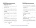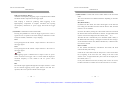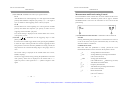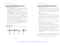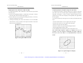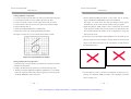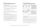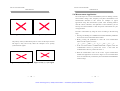
1
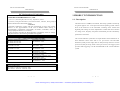
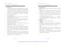
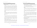
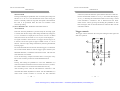
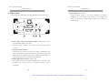
Artisan Technology Group is your source for quality new and certified-used/pre-owned equipment • FAST SHIPPING AND DELIVERY • TENS OF THOUSANDS OF IN-STOCK ITEMS • EQUIPMENT DEMOS • HUNDREDS OF MANUFACTURERS SUPPORTED • LEASING/MONTHLY RENTALS • ITAR CERTIFIED SECURE ASSET SOLUTIONS SERVICE CENTER REPAIRS Experienced engineers and technicians on staff at our full-service, in-house repair center WE BUY USED EQUIPMENT Sell your excess, underutilized, and idle used equipment We also offer credit for buy-backs and trade-ins www.artisantg.com/WeBuyEquipment InstraView REMOTE INSPECTION LOOKING FOR MORE INFORMATION? Visit us on the web at www.artisantg.com for more information on price quotations, drivers, technical specifications, manuals, and documentation SM Remotely inspect equipment before purchasing with our interactive website at www.instraview.com Contact us: (888) 88-SOURCE | [email protected] | www.artisantg.com GOS-6112 OSCILLOSCOPE GOS-6112 OSCILLOSCOPE USER MANUAL USER MANUAL CONTENTS PAGE 1. PRODUCT INTRODUCTION................................................ 1 1-1.Description………………………………………………. 1 1-2.Feature…………………………………………………... 2 2. TECHNICAL SPECIFICATION………………………….. 4 3. PRECAUTIONS BEFORE OPERATION…….………….. 3-1.Unpacking the instrument………………….………….. 3-2.Checking the Line Voltage…………………..…………. 3-3.Environment……………………………………..……… 3-4.Equipment Installation and Operation……………….... 3-5.CRT Intensity…………………………………………… 3-6.Withstanding Voltage of Input Terminals……………... 4. 7 7 7 8 8 8 8 PANEL INTRODUCTION……………………..………….. 9 4-1.Front Panel………………………………………………. 11 4-2.Rear Panel……………………………………….……… 30 5. OPERATION METHOD………………………………...… 5-1.Readout Display……………………………………..…... 5-2.Connecting Input Signals..……………………………… 5-3.Adjustment and Checks………………………………… 5-4.Function Check…..……………………………………… 5-5.Basic Operation………….….…………………………... 5-6.Measurement Application………………………………. 32 32 34 35 37 39 47 6. MAINTENANCE…………………………………………… 6-1.Fuse Replacement……………………………………….. 6-2.Line Voltage…………………………………………..…. 6-3.Cleaning…………………………………………………. 51 51 51 52 7. BLOCK DIAGRAM………………………………………... 53 i SAFETY TERMS AND SYMBOLS These terms may appear in this manual or on the product: WARNING. Warning statements identify condition or practices that could result in injury or loss of life. CAUTION. Caution statements identify conditions or practices that could result in damage to this product or other property. The following symbols may appear in this manual or on the product: DANGER ATTENTION High Voltage refer to Manual Artisan Technology Group - Quality Instrumentation ... Guaranteed | (888) 88-SOURCE | www.artisantg.com Protective Conductor ii Earth(ground) Terminal GOS-6112 OSCILLOSCOPE GOS-6112 OSCILLOSCOPE USER MANUAL USER MANUAL FOR UNITED KINGDOM ONLY NOTE: This lead/appliance must only be wired by competent persons WARNING: THIS APPLIANCE MUST BE EARTHED IMPORTANT: The wires in this lead are coloured in accordance with the following code: Green/ Yellow: Blue: Brown: Earth Neutral Live (Phase) This cable/appliance should be protected by a suitably rated and approved HBC mains fuse: refer to the rating information on the equipment and/or user instructions for details. As a guide, cable of 0.75mm2 should be protected by a 3A or 5A fuse. Larger conductors would normally require 13A types, depending on the connection method used. Any moulded mains connector that requires removal /replacement must be destroyed by removal of any fuse & fuse carrier and disposed of immediately, as a plug with bared wires is hazardous if a engaged in live socket. Any re-wiring must be carried out in accordance with the information detailed on this label. As the colours of the wires in main leads may not correspond with the colours marking identified in your plug/appliance, proceed as follows: The wire which is coloured Green & Yellow must be connected to the Earth terminal marked with the letter E or by the earth symbol or coloured Green or Green & Yellow. The wire which is coloured Blue must be connected to the terminal which is marked with the letter N or coloured Blue or Black. The wire which is coloured Brown must be connected to the terminal marked with the letter L or P or coloured Brown or Red. If in doubt, consult the instructions provided with the equipment or contact the supplier. iii Artisan Technology Group - Quality Instrumentation ... Guaranteed | (888) 88-SOURCE | www.artisantg.com iv GOS-6112 OSCILLOSCOPE GOS-6112 OSCILLOSCOPE USER MANUAL USER MANUAL EC Declaration of Conformity We GOOD WILL INSTRUMENT CO., LTD. (1) No. 95-11, Pao-Chung Rd., Hsin-Tien City, Taipei Hsien, Taiwan 1.PRODUCT INTRODUCTION 1-1. Description (2) Plot 522, Lorong Perusahaan Baru 3, Prai Industrial Estate, 13600 Prai, Penang, Malaysia declares that the below mentioned product GOS-6112 is herewith confirmed to comply with the requirements set out in the Council Directive on the Approximation of the Law of Member States relating to Electromagnetic Compatibility (89/366/EEC, 92/31/EEC, 93/68/EEC) and Low Voltage Equipment Directive (73/23/EEC). For the evaluation regarding the Electromagnetic Compatibility and Low Voltage Equipment Directive, the following standards were applied: EN 61326-1: Electrical equipment for measurement, control and laboratory use –– EMC requirements (1997+A1: 1998) Conducted and Radiated Emissions Electrostatic Discharge EN 55011 class B: 1991 EN 61000-4-2: 1994 EN 55022 class B: 1994 Current Harmonic Radiated Immunity EN 61000-3-2: 1995 ENV 50140: 1993 Voltage Fluctuation Electrical Fast Transients EN 61000-3-3: 1995 EN 61000-4-4: 1995 Surge Immunity ———————————— EN 61000-4-5: 1995 Conducted Susceptibility ———————————— EN 61000-4-6: 1996 Power Frequency Magnetic field ———————————— EN 61000-4-8: 1993 Voltage Dips/ Interrupts ———————————— EN 61000-4-11: 1994 The GOS-6112 is a 100MHz, two-channel, dual-sweep, portable oscilloscope for general purpose use. A microprocessor-based operating system controls most of the functions of the instrument, including cursor readout and digitized panel setting. On-screen alphanumeric readout and cursor function for voltage, time, frequency and phase measurement provide extraordinary operational convenience. The vertical deflection system has two input channels. Each channel has 11 basic deflection factors from 2mV to 5V per division. The horizontal deflection system provides single, dual or delayed sweeps from 0.5s to 50ns per division (delayed sweep, 50ms to 50ns per division). The trigger system provides stable triggering over the full bandwidth of the vertical deflection system. Low Voltage Equipment Directive 73/23/EEC & amended by 93/68/EEC Safety Requirements EN 61010-1: 1990+A1: 1992+A2: 1995 IEC 61010-1: 1990+A1: 1992+A2: 1995 v Artisan Technology Group - Quality Instrumentation ... Guaranteed | (888) 88-SOURCE | www.artisantg.com 1 GOS-6112 OSCILLOSCOPE GOS-6112 OSCILLOSCOPE USER MANUAL USER MANUAL 1-2.Features Additionally, the oscilloscope offers several other features: 1) High intensity and internal graticule CRT 6) Trigger signal output The signal selected by the TRIGGER SOURCE is available. This The oscilloscope employs a high intensity 6-inch retangular type output may be used to connect to a frequency counter or other cathode-ray tube with red internal graticule. It displays clear readable instrument. traces even at high sweep speeds. Internal graticule lines eliminate parallax-viewing error between the trace and the graticule line. 7) Panel setups lock To avoid unintentional touch of the setting, the feature is extremely useful for long term and repetitive measurements that used to be 2) Temperature compensation The oscilloscope uses a temperature compensation circuit to reduce the performed under the same test condition of the oscilloscope setting. 8) LED indicator and buzzer alarm drift of base line and DC balance. The LED’s located in the front panel assist operation and indicated 3) 20MHz bandwidth limit When it is hard to observe or trigger a signal because a high-frequency additional information. Incorrect operation and the electrical end component is superimposed on the signal, use the 20MHz BWL position of control knobs are indicated by a warning beep. function to reduce the bandwidth of the vertical deflection system and 9) SMD manufacturing technology trigger system to 20MHz. The instrument is built by using the most advanced SMD technology 4) TV triggering Exclusive TV sync separator circuit technology provides stable TV so as to reduce the number of internal wiring and shorten the foil route signal measurements on fields, frames and lines. on the pc board. This will also greatly increase the high frequency performance and the reliability of the product. 5) Z-axis intensity modulation For applying a blanking signal from an external source. The trace displayed on the screen may be intensity-modulated where pulse signal or time-scale marks are required. 2 Artisan Technology Group - Quality Instrumentation ... Guaranteed | (888) 88-SOURCE | www.artisantg.com 3 GOS-6112 OSCILLOSCOPE GOS-6112 OSCILLOSCOPE USER MANUAL USER MANUAL 2.TECHNICAL SPECIFICATIONS Sensitivity Sensitivity Accuracy 2mV~5V/DIV,11 step in 1-2-5 sequence ±3% (5 DIV at the center display ) Continuously variable to 1/2.5 or less than Vernier Vertical Sensitivity panel-indicated value Frequency Bandwidth(-3dB) DC ~ 100MHz (2mV/DIV:DC ~ 20MHz) Rise Time 3.5ns (2mV/DIV:17.5ns) VERTICAL Signal Delay Leading edge can be monitored Maximum Input Voltage 400V (DC+AC) at 1kHz or less DEFLECTION Input Coupling AC, DC, GND Input Impedance 1MΩ±2% // 25pF approx. SYSTEM CH1,CH2,DUAL(CHOP/ALT),ADD(DIFF mode can Vertical Modes be established when the CH2 is in the INV mode) CHOP Repetition Frequency Approx. 250kHz. Polarity (INV) CH2 only Bandwidth Limited 20MHz Common-mode 50:1 or better at 50kHz Rejection Ration Dynamic Range 8 div at 60MHz, 5 div at 100MHz. Trigger Modes AUTO, NORM, TV Trigger Source CH1, CH2, LINE, EXT Trigger Coupling AC, DC, HFR, LFR Trigger Slope +/- polarity or TV sync polarity Mode Frequency INT EXT 10Hz~20MHz 0.35DIV 50mVpp AUTO 20MHz~100MHz 1.5DIV 150mVpp TRIGGER Trigger Sensitivity NORM DC~20MHz 0.35DIV 50mVpp 20MHz~100MHz 1.5DIV 150mVpp SYSTEM TV Sync signal 1DIV 200mVpp INT : ± 4 DIV or more Trigger Level Range EXT : ± 0.4 V or more TV Sync TV-V,TV-H Max. External Input Voltage 400V (DC + AC peak) at 1kHz External Input Impedance 1MΩ± 5% ∕ ∕25pF approx. 4 Horizontal Modes MAIN(A), ALT, DELAY(B) 50nS~0.5S/DIV, continuously variable A (main) Sweep Time (UNCAL) 50nS~50mS/DIV HORIZONTAL B (delay) Sweep Time Accuracy ± 3% (± 5% at × 10 MAG) DEFLECTION Sweep Magnification × 10 (maximum sweep time 5nS/DIV) Hold Off time Variable SYSTEM Delay Time 1uS~5S Delay Jitter 1/20000 or less Alternate Separation Variable X-axis, Y-axis selectable X-axis: CH1, CH2Æ 2mV~5V/DIV ± 3% Sensitivity Accuracy EXT Æ 0.1V/DIV ± 5% X-Y Y-axis: CH1,CH2Æ 2mV~5V/DIV ± 3% OPERATION X-axis Bandwidth DC~500kHz (-3dB) Phase Error 3°or less at DC~50kHz Cursor Measurement Function ΔV,ΔV%,ΔVdB,ΔT,1/ΔT,ΔT%,Δ Θ . Cursor Resolution 1/100 DIV Effective Cursor Range Vertical: ± 3 DIV; horizontal: ± 4 DIV Panel setting Vertical: V/DIV (CH1,CH2),UNCAL, ADD, CURSOR INV, P10, AC/DC/GND. READOUT Horizontal: S/DIV (MTB, DTB), UNCAL FUNCTION x 10MAG, Delay time, Hold-off. Trigger: Source, Coupling, Slope, Level , TV-V/TV-H. Others: X-Y, LOCK. 6-inch rectangular type with internal graticule Type 0%, 10%, 90% and 100% markers. 8 x 10 DIV (1 DIV = 1 cm) CRT Phosphor P31 Accelerating Potential 12kV approx. External intensity modulation Coupling DC Z-AXIS Voltage 5V or more INPUT Maximum Input Voltage 30V (DC+AC peak) at 1kHz or less Bandwidth DC~5MHz Artisan Technology Group - Quality Instrumentation ... Guaranteed | (888) 88-SOURCE | www.artisantg.com 5 GOS-6112 OSCILLOSCOPE GOS-6112 OSCILLOSCOPE USER MANUAL TRIGGER SIGNAL OUTPUT CALIBRATOR OUTPUT SPECIAL FUNCTION USER MANUAL Voltage Frequency Response Output Impedance Waveform Voltage Impedance 25mV/DIV approx. in 50Ω termination DC~10MHz 50Ω approx. 1kHz ± 5%, square wave 2Vpp ± 2% 2kΩ approx. Panel Setups Lock Provided Voltage AC 110V, 120V, 230V ± 10% selectable LINE POWER Frequency 50Hz or 60Hz REQUIREMENT Power Consumption Approx. 90VA, 70W(max.) Indoor use Altitude up to 2000 m Ambient temperature : To satisfy specifications : 10° to 35℃ ( 50° to 95°F ) OPERATING ENVIRONMENT Maximum operating ranges: 0° to 40℃( 32 °to 104°F ) Relative humidity:85% RH(max.) non condensing Installation Category II Pollution degree 2 STORAGE TEMPERATURE -10° to 70℃, 70%RH(maximum) & HUMIDITY Dimensions 310 W × 150 H × 455 D (mm) MECHANICAL SPECIFICATION Weight Approx. 9kgs (19.8 lbs) Power cord….............……….. 1 Instruction manual…………… 1 ACCESSORIES Probe (×1/×10)…………..… 2 3.PRECAUTIONS BEFORE OPERATION 3-1.Unpacking the Oscilloscope The product has been fully inspected and tested before shipping from the factory. Upon receiving the instrument, please unpack and inspect it to check if there is any damages caused during transportation. If any sign of damage is found, notify the bearer and/or the dealer immediately. 3-2.Checking the Line Voltage The oscilloscope can be applied any kind of line voltage shown in the table below. Before connecting the power plug to an AC line outlet, make sure the voltage selector of the rear panel is set to the correct position corresponding to the line voltage. It might be damaged the instrument if connected to the wrong AC line voltage. WARNING. To avoid electrical shock the power cord protective grounding conductor must be connected to ground. When line voltages are changed, replace the required fuses shown as below: Line voltage Range Fuse 110V 90-110V T 1A 250V 120V 108-132V Line voltage Range Fuse 230V 195-250V T 0.4A 250V WARNING. To avoid personal injury, disconnect the power cord before removing the fuse holder. 6 Artisan Technology Group - Quality Instrumentation ... Guaranteed | (888) 88-SOURCE | www.artisantg.com 7 GOS-6112 OSCILLOSCOPE GOS-6112 OSCILLOSCOPE USER MANUAL USER MANUAL 4. PANEL INTRODUCTION 3-3.Environment The normal ambient temperature range of this instrument is from 0° to After the instrument is switched on, all the important settings are displayed 40°C (32° to 104°F). To operate the instrument over this specific in the readout. The LED’s located on the front panel assist operation and temperature range may cause damage to the circuits. indicate additional information. Incorrect operation and the electrical end Do not use the instrument in a place where strong magnetic or electric positions of control knobs are indicated by a warning beep. field exists as it may disturb the measurement. 3-4.Equipment Installation, and Operation Except the Power pushbutton (POWER), the Focus control (FOCUS), the Ensure there is proper ventilation for the vents in the oscilloscope case. If Scale Illumination control (ILLUM) and the Trace Rotation control, all this equipment is used not according to the specification, the protection other controls are electronically selected, and their functions and settings provided by the equipment may be impaired. can therefore be stored. 3-5.CRT Intensity To prevent permanent damage to the CRT phosphor, do not make the The front panel is subdivided into six sections: CRT trace brighten excessively or leave the spot stay for an unreasonably z Display controls long time. z Vertical controls z Horizontal controls z Trigger controls z Measurement and SAVE/RECALL controls z Input connectors 3-6.Withstanding Voltages of Input Terminals The withstanding voltages of the instrument input terminals and probe Input terminals are shown in the following table. Do not apply voltages higher than these limits. Input terminal Maximum input voltage CH1, CH2, inputs EXT TRIG input Probe inputs Z AXIS input 400V (DC + AC peak) 400V (DC + AC peak) 600V (DC + AC peak) 30V (DC + AC peak) CAUTION. To avoid instrument damage, do not apply exceeding maximum input voltages of the frequency less than 1 kHz to the instrument. 8 Artisan Technology Group - Quality Instrumentation ... Guaranteed | (888) 88-SOURCE | www.artisantg.com 9 GOS-6112 OSCILLOSCOPE GOS-6112 OSCILLOSCOPE USER MANUAL USER MANUAL 4-1.Front Panel Display controls The display controls adjust the on-screen appearance of the waveform and provide a probe compensation signal source. CAL 2Vp-p ILLUM FOCUS TRACE ROTATION 1 KHz 6 INTEN TRACE/ READOUT POWER OFF 5 4 3 2 1 (1).POWER – Pushbutton and symbols for ON(1) and OFF(0). When switch on the oscilloscope to have all LEDs lighted and the software version will be displayed on the screen. After the Internal test Front panel of GOS-6103 is completed successfully, the normal operation mode is present. Then the last settings become activated and the LED indicates the ON condition. (2).INTEN – TRACE/READOUT – Control knob with associated pushbutton and readout display. The control knob is used for adjusting the traces and readout intensity. Turning the knob clockwise to increase the intensity and turning it counterclockwise to decrease the intensity. The TRACE/READOUT pushbutton is for selecting the intensity function and indicates the letter “TRACE INTEN” or “READOUT INTEN” in the readout. Press the pushbutton briefly for the following sequences: “TRACE INTEN” — “READOUT INTEO” — “TRACE INTEN” 10 Artisan Technology Group - Quality Instrumentation ... Guaranteed | (888) 88-SOURCE | www.artisantg.com 11 GOS-6112 OSCILLOSCOPE GOS-6112 OSCILLOSCOPE USER MANUAL USER MANUAL (3).TRACE ROTATION (7).20MHz BWL – Pushbutton with indicator LED. The TRACE ROTATION is for aligning the horizontal trace in Briefly pressing the pushbutton, the bandwidth is reduced to approx. parallel with graticule lines. This potentiometer can be adjusted with a 20MHz, and the measurement is made by eliminating undesired high small screwdriver. frequency signal from the waveform. Also the high frequency component over 20MHz is eliminated from the trigger signal. (4).FOCUS The control knob effects both the trace and the readout sharply. (8).CURSOR POS - △V1/2 — Pushbutton with double function and associated indicator LED. (5).ILLUM The knob controls the graticule illumination brightness. The function of Cursor Position or CH1/CH2 Position can be selected only after the pushbutton of Cursor Function is pressed to appear (6).CAL The terminal provides a reference signal of 2Vp-p at 1kHz for probe adjustment. enabling their cursor measurement. Press the pushbutton once briefly to have the related LED lighted, the CH1/CH2 POSITION control Vertical controls knob is then operated as CURSOR 1/CURSOR 2 POSITION control. The vertical controls select the displayed signals and control the △V1/2 amplitude characteristics. The function is required and available only in DUAL mode in 9 VERTICAL POSITION C1 8 CURSOR POS 20MHz BWL 7 combination with △V (Voltage) measurement. Pressing and holding 10 the pushbutton, then switch between CH1 and CH2, the measured result will be displayed by the readout with “△V1…” or “△V2…” POSITION providing the defection coefficient is calibrated. The settings of the C2 ALT/ CHOP/ ADD TRACE SEP 11 VOLTS/DIV VOLTS/DIV 13 12 14 2mV 5V 15 5V CH1 AC/DC GND AC/DC 16 GND The vertical trace position of channel 2 can be set with the control knob, which is also operated as CURSOR 2 position control in cursor Px10 Px10 which is also operated as CURSOR 1 position control in cursor (10)CH2 POSITION – C2 — Control knob has several functions. CH2 VAR The vertical trace position of channel 1 can be set with the control knob, measurement mode. 2mV VAR cursors must be related to the signal of the selected channel. (9).CH1 POSITION – C1 — Control knob with double function. INV V1/2 measurement mode. In alternate time base mode, this control knob 17 19 18 20 can be used to separate the DELAY time base trace from the MIAN time base trace. Please note TRACE SEP (11). 12 Artisan Technology Group - Quality Instrumentation ... Guaranteed | (888) 88-SOURCE | www.artisantg.com 13 GOS-6112 OSCILLOSCOPE GOS-6112 OSCILLOSCOPE USER MANUAL USER MANUAL (11)TRACE SEP (13)CH1 VOLTS/DIV. The instrument contains a trace separate function which is required in (14)CH2 VOLTS/DIV– Control knob for channel 1/channel 2 has double the alternate time base mode to separate the DELAY time base trace(s) function. from the MAIN time base in vertical direction. Consequently this Turning the knob clockwise to increase the sensitivity in 1-2-5 sequence function is only available in alternate time base mode. Press the and turning it in the opposite direction (CCW) to decrease. The pushbutton once to have the related LED lighted, the CH1 POSITION available range is from 2mV/div up to 5V/div. The knob is control knob is then operated as vertical position control for the automatically switched inactive if the related channel is switched off. trace(s) of the DELAY time base. The deflection coefficients and additional information regarding the active channels are displayed in the readout. (12)ALT/CHOP/ADD-INV The pushbutton has several functions, which are required and available ie. “CH1=deflection coefficient, input coupling”. The “=” symbolizes only when both channels are active. calibrated measuring conditions and is replaced by the “>” symbol in ALT– Displays in the readout, indicates alternate channel switching. uncalibrated conditions. After each time base sweeps the instrument internally, switches over (15)CH1-VAR. from channel 1 and channel 2 and vice versa. (16)CH2-VAR — Pushbutton with double function. CHOP– Indicates chopper mode. CH1/CH2 The channel switching occurs constantly between channel 1 and Pressing briefly the CH1(CH2) button to set the cannel 1 (channel 2) of channel 2 during each sweep. the instrument on, the deflection coefficient will be displayed in the ADD– Displays in the readout, indicates additional mode. readout indicating the current conditions (“CH1…”/ “CH2…”). Whether the algebraic sum (addition) or the difference (subtraction) of VAR both input signals is displayed, depends on the phase relationship and Pressing and holding the pushbutton to select the VOLTS/DIV function the INV setting. As a result, both signals are displayed as one signal. between attenuator and vernier (variable). The current setting is For correct measurements, the deflection coefficients for both channels displayed by the “>” symbol in the readout. must be equal. After switching on the VAR, turn the VOLTS/DIV control knob INV—Pressing and holding the pushbutton to set the channel 2 invert counterclockwise to reduce the signal height, and the deflection function on or off. The invert on condition is indicated with a horizontal coefficient becomes uncalibrated. bar above “CH2” in the readout. The invert function causes the signal display of channel 2 to be inverted by 180o. 14 Artisan Technology Group - Quality Instrumentation ... Guaranteed | (888) 88-SOURCE | www.artisantg.com 15 GOS-6112 OSCILLOSCOPE GOS-6112 OSCILLOSCOPE USER MANUAL USER MANUAL (17)CH1 AC/DC. Horizontal controls: (18)CH2 AC/DC The horizontal controls select the time base operation mode and adjust the Pressing the pushbutton briefly to switch over from AC (~ symbol) to horizontal scale, position and magnification of the signal. DC (= symbol) input coupling. The setting is displayed in the readout with the deflection coefficient. (19)CH1 GND– P×10 (20)CH2 GND – P×10 –Pushbutton has two functions. GND Each time when the pushbutton is pressed briefly, the input of the vertical amplifier is grounded. It is displayed in the readout as an earth (ground) symbol “ ”. P×10 Pressing and holding the pushbutton to select the indicated deflection coefficient of the channel displayed in the readout between 1:1 and 10:1. The probe factor of 10:1 is displayed in the readout with the probe symbol in front of channel indication (e.g. “P10”, CH1) When proceed cursor voltage measurement, the probe factor will be automatically included. The symbol must not be activated unless a 10:1 attenuator (21)TIME/DIV– Control knob with double function. Turning the knob clockwise to reduce the deflection coefficient in a 1-2-5 sequence and turning it in the opposite direction (CCW) to increase. The time coefficient(s) will be displayed in the readout. In MAIN time base (MTB) mode, time deflection coefficients between probes are used. 0.5s/div and 50ns/div can be chosen in 1-2-5 sequence, if the ×10 MAG function is not activated. During alternate (ALT) and DELAY time base (DTB) operation, the control knob changes the DELAY time base setting in 1-2-5 sequence. The available deflection coefficient range is from 50ms/div up to 50ns/div (without ×10 MAG), but the availability depends on the MAIN time base setting. The internal control of the oscilloscope prevents the DELAY time deflection coefficient from becoming higher than the MAIN deflection coefficient, as such an operation condition would make no sense. 16 Artisan Technology Group - Quality Instrumentation ... Guaranteed | (888) 88-SOURCE | www.artisantg.com 17 GOS-6112 OSCILLOSCOPE GOS-6112 OSCILLOSCOPE USER MANUAL USER MANUAL (22)MAIN/ALT/DELAY—X-Y – Pushbutton for time base mode coefficient (uncalibrated i.e. “DLY>0.125ms”). The width of the selection. window segment decreases when the DELAY time coefficient is set to The instrument contains two-time base designated MAIN and DELAY. a lower value (higher time deflection speed). With the aid of the DELAY time base, signal parts displayed by the For better reading, the vertical position of the DELAY time base trace MAIN time base can be expanded in X-direction. The expansion ratio position can be shifted (please note TRACE SEP (11)). depends on the time deflection coefficient ratio of both time bases (ie. DELAY “MTB=0.1ms”, “DTB=1μs”=100). With higher expansion ratio the In the DELAY time base mode, the display of the MAIN traces, the DELAY time base trace intensity reduces. Each time when press the window sector and the MAIN time coefficient will disappear from the pushbutton briefly, the time base mode changes in the sequence of readout. As the trace separation is no longer required under the MAIN-ALT-DELAY-MAIN. The actual setting is displayed in the circumstances, the function would be switched off too. Consequently, readout. only the DELAY time coefficient is displayed by the readout. MAIN X-Y The TIME/DIV control knob is operated only under the MAIN time Switch on or off the X-Y mode by pressing and holding the button. In base mode. The readout then displays the main time coefficient alone. the X-Y mode, the deflection coefficient is displayed in the readout. The time base setting for this condition will be stored if the time base The Y axis input is selected by setting the vertical mode pushbutton to mode is changed. the CH1, CH2 and both modes, and the X axis input is selected by ALT setting the TRIGGER SOURCE pushbutton to the CH1, CH2 and EXT. If the alternate time base mode is selected, the TIME/DIV knob only (23)H POSITION controls the DELAY time base switch. The alternate time base mode is The control knob enables a horizontal position shift of the signals. In a sub-function of the DELAY time base mode and both time base combination with ×10 MAG the function makes it possible to shift any traces can be displayed simultaneously. Consequently the readout can part of the signal on the screen. display both time deflection coefficient. A window sector which (24)×10 MAG—SETUPS LOCK— Pushbutton has double function and indicates part of signal is also visible on the MAIN trace and is associated MAG LED. displayed by the DELAY time base. Each time when this pushbutton is pressed, the MAG LED located The window segment can be shifted horizontally by the DELAY TIME above will be switch on or off. If the MAG LED is lighted, the signal control continuously. The difference between the beginning of both the display in all time base modes will be expanded 10 folds and MAIN time base trace and the window sector shows the delay time. consequently only a tenth part of the signal curve is visible. The The information is also displayed in the readout with an approximate interesting part of the signal can be made visible with the aid of the H. value (e.g. “DLY=0.125ns”) related to the calibrated MAIN time POSITION control. 18 Artisan Technology Group - Quality Instrumentation ... Guaranteed | (888) 88-SOURCE | www.artisantg.com 19 GOS-6112 OSCILLOSCOPE GOS-6112 OSCILLOSCOPE USER MANUAL USER MANUAL SETUPS LOCK coefficient (reduce the deflection speed) and the deflection coefficient Pressing and holding the pushbutton, then switch the panel setups lock becomes uncalibrated. Instead of “A=10μs”, the readout then displays function on or off. To avoid unintentional touch of the setting, the “A>10μs” indicating the uncalibrated condition. This setting is stored feature is extremely useful for long term and repetitive measurements if the instrument is switched to ALT or DELAY time base mode. that need to be performed under the same test condition of the Switch off the VAR by pressing and holding the pushbutton of time oscilloscope setting. base mode again, then set the time deflection coefficient back into the (25)AUTO RANGE-VAR – Pushbutton with double function. calibrated condition. AUTO RANGE Each time when the pushbutton is pressed briefly the incoming signal Trigger controls is selected, then the time range would change automatically and approx. The trigger controls determine the sweep start timing for both signal and 1.6 to 4 waveforms are displayed on the screen. If in the ×10 MAG dual trace operation. mode, the ten times of waveform of 1.6 to 4 cycles can be displayed. TRIGGER LEVEL For signal of 100Hz or in the absence of a trigger, the time range is set to 5ms/div, and for the signals of approx. 8MHz or more, it is set to 27 50ns/div. The time range change automatically following the different - MODE incoming signal. + SOURCE COUPLING ATO CH1 NML CH2 DC HFR TV The AUTO RANGE does not function when the trigger is not obtained. AC EXT LFR The AUTO RANGE functions with the trigger signal selected by the TRIGGER SOURCE, COUPLING and LEVEL control. The time base 26 28 HO mode should be set to MAIN. 29 DELAY TIME In case of measuring a complex waveform such as a TV signal, it may take several seconds to perform the AUTO RANGE function. 30 SLOPE TV-V/ TV-H 32 31 VAR Pressing and holding the pushbutton to select the TIME/DIV (21) control knob function between time base switch and vernier (variable). The variable function is activated in the MAIN time base only. After switching on the VAR, the time deflection coefficient is still calibrated until further adjustments are made. Turn the TIME/DIV (21) control knob counter clockwise to increase the time deflection 20 Artisan Technology Group - Quality Instrumentation ... Guaranteed | (888) 88-SOURCE | www.artisantg.com 21 GOS-6112 OSCILLOSCOPE GOS-6112 OSCILLOSCOPE USER MANUAL USER MANUAL (26)MODE – Pushbutton and indicator LEDs. Pressing the pushbutton to select the trigger mode. The actual setting When the setting (voltage) value is out of the changing portion of the is indicated by a LED. observation waveform, the synchronization sweep stops. Sometimes a Each time when the MODE pushbutton is pressed the trigger mode “?” will be displayed on the left of the valued display, that indicates changes in the sequence: that direct reading is impossible if AC, HFR, LFR coupling or VAR of ATO—NML—TV—ATO vertical deflection is set. (28)COUPLING –Pushbutton and indicator LEDs. ATO (Auto) Select the automatical mode, the sweep free-runs will display a Pressing the pushbutton to select the trigger coupling. The actual baseline trace when there is no trigger signal or the frequency is below setting is indicated by a LED and by the readout (“source, slope, AC”). 10Hz. The setting of triggering level changed only when the TRIGGER Each time when the COUPLING pushbutton is pressed the trigger LEVEL control is adjusted to a new level setting. coupling changes in the sequence: AC—DC—HFR—LFR NML (Normal) Select the normal mode, the input signal will trigger the sweep when AC the TRIGGER LEVEL control is set within the peak-to-peak limits of Attenuates trigger signal frequency components below 10Hz and an adequate trigger signal. When the sweep is not triggered, no blocks the DC component of the signal. baseline trace will be displayed. AC coupling is useful for triggering on AC waveforms that have a TV large DC offset. Separate the video sync signal from the composite waveform and DC direct it to the triggering circuit. The horizontal or vertical sync signals Couples DC and all frequency components of a triggering signal to the are selected by TV-V/TV-H pushbutton. Please refer to the trigger circuitry. TV-V/TV-H (31). DC coupling is useful for most signals, especially for providing a stable display of low-frequency or low-repetition-rate signals. (27)LEVEL—Control knob Turning the control knob causes a different trigger input setting HFR (High Frequency Reject) (voltage), and set to a suitable position for the starting of triggered Attenuates high-frequency triggering signal components above 40kHz. sweep of the waveform. An approximate trigger level setting (voltage) HFR coupling is useful for providing a stable display of low-frequency value will be displayed in the readout. When rotate clockwise the components of complex waveforms and eliminates high-frequency control knob, the trigger point moves toward the positive peak of the interference from the trigger signal. trigger signal and rotate it counterclockwise to move the trigger point toward the negative peak of the trigger signal. 22 Artisan Technology Group - Quality Instrumentation ... Guaranteed | (888) 88-SOURCE | www.artisantg.com 23 GOS-6112 OSCILLOSCOPE GOS-6112 OSCILLOSCOPE USER MANUAL USER MANUAL LFR (Low Frequency Reject) Attenuates low-frequency triggering signal components below 40kHz (30)DELAY-HO—Control knob with a double function and associated LED. and blocks the DC component of the trigger signal. The control knob has two different functions depending on the time LFR coupling is useful for producing stable triggering on the base mode. high-frequency components of complex waveforms and rejecting HO (Hold-off time) low-frequency interference or power supply hum from the trigger In MAIN time base mode, the control knob applies to the hold off signal. time setting, the HO-LED associated with the knob is dark, the hold off time is set to minimum. (29)SOURCE—Pushbutton and associated LEDs. Switch on the LED by turning the control knob clockwise and extend Pressing the pushbutton to select the trigger signal source or the X the hold off time until the maximum is reached. An approximate hold signal for an X-Y operation. The actual setting is indicated in a LED off time value will be displayed in the readout (“HO: and by the readout (“SOURCE”, slope, coupling). The hold off time is automatically set to minimum (LED is dark), if CH1 the MAIN time base setting is changed. The hold off time setting is The signal applied to the channel 1 input connector is the source of stored and deactivated if ALT (MAIN and DELAY) or DELAY time the trigger signal. base mode is selected. CH2 DELAY TIME The signal applied to the channel 2 input connector is the source of In ALT (MAIN and DELAY) and DELAY time mode, the knob the trigger signal. controls the delay time setting. %”). Under the ALT time base mode, the delay time is visible on the main (Line) The triggering signal is obtained from a sample of the AC power trace, beginning at the trace start and source waveform. The trigger source is useful when the displayed window sector. An approximate delay time value will be displayed in waveform frequency is time related to the AC power source the readout (“DLY=”). frequency. If only select DELAY time base, the delay time can also be varied, EXT but there would be no window sector as the main trace is not visible. The external signal applied through the EXT input connector is used for the external triggering source signal. When in the dual X-Y operation, the X-axis operates with the external signal. 24 Artisan Technology Group - Quality Instrumentation ... Guaranteed | (888) 88-SOURCE | www.artisantg.com 25 ending at the start of the GOS-6112 OSCILLOSCOPE GOS-6112 OSCILLOSCOPE USER MANUAL USER MANUAL (31)TV-V/TV-H—Pushbutton for video sync signal selection. Measurement and Panel setting Control TV-V The measurement section controls the on-screen readout and the cursor Start the main trace at the beginning of a video signal field. SLOPE measurements. For more information, please refer to page 9 “PANEL polarity must match the composite sync polarity (i.e, “–” for negative INTRODUCTION” section for the instrument to store and recall the sync) to obtain TV field triggering on the vertical sync pulse. panel setting. TV-H Start the main trace at the beginning of a video signal line. SLOPE MEM 0-9 CURSOR FUNCTION SAVE RECALL ON/OFF polarity must match the composite sync polarity to obtain TV line triggering on the horizontal sync pulse. The current setting is displayed in the readout under item “source, video polarity, TV-H”. (32)SLOPE ( 33 34 (33)CURSOR FUNCTION-ON/OFF—Pushbutton with two functions. )—Pushbutton for the triggering slope or video ON/OFF polarity selection. Pressing and holding either pushbutton to switch both cursor lines on If in the AUTO or NML trigger mode, briefly pressing the pushbutton or off. As the cursor lines are part of the readout, they are visible only to select the slope of the signal which is used for triggering the time when the readout is switched on. base generator. Each time when the pushbutton is briefly pressed, the CURSOR FUNCTION slope direction will switch from falling edge to rising edge, and vice Each time when the pushbutton is briefly pressed the seven versa. measurement functions will be selected in the sequence as below: The current setting is displayed in the readout under item “source, △V : Voltage difference measurement. SLOPE, coupling”. △V% : Voltage difference percentage measurement If in the TV trigger mode, briefly pressing the pushbutton to select the video polarity, which will be displayed in the readout with a “+” (5div=100% reference) △VdB : signal. Voltage gain measurement. (5div=odB reference, △VdB=20 log, div/5div). symbol of positive video signal and a “–” symbol of negative video △T : Time difference measurement. 1/△T : Frequency measurement. △T% : Time difference percentage measurement. (5div=100% reference). △θ : Phase measurement. (5div=350o reference). 26 Artisan Technology Group - Quality Instrumentation ... Guaranteed | (888) 88-SOURCE | www.artisantg.com 27 GOS-6112 OSCILLOSCOPE GOS-6112 OSCILLOSCOPE USER MANUAL (34) MEMO- 9 USER MANUAL —SAVE/RECALL (35)CH1—Input BNC socket The instrument contains 10 non-volatile memories, which can be used This BNC socket is the signal input for channel 1. In X-Y mode, by the operator to save instrument setting and to recall them. It relates signals at this input are used for the Y or X deflection. The outer to all controls which are electronically selected. (ground) connection is galvanically connected to the instrument Press ground and consequently to the safety earth contact of the line/mains or pushbutton to select the memory location. The readout then indicates the letter “MEN” followed by a cipher between 0 and 9. Each time the pushbutton is briefly pressed the memory plug. (36)CH2—Input BNC socket location cipher increases until the number 9 is reached. The This BNC socket is the signal input for channel 2. In X-Y mode, pushbutton is similar but decreases the memory location cipher until signals at this input are used for the X or Y deflection. The outer the number 0 is reached. Pressing and holding SAVE for approx. 3 (ground) connection is galvanically connected to the instrument seconds to write the instrument settings in the memory and indicate ground and consequently to the safety earth contact of the line/mains the associated readout information of “SAVED”. plug. To recall a front panel setup, select a memory location as described (37)Ground socket—Banana Socket galvanically connected to safety above. Recall the settings by pressing and holding the RECALL earth. pushbutton for approx. 3 seconds, the readout then indicates the This socket can be used a reference potential connection for DC and low frequency signal measurement purposes. associated readout information of “RECALLED”. (38)EXT—This BNC socket is the external trigger signal input. Input connectors In dual X-Y mode, signals at this input are used for the X deflection. The input section is where the input signals are commonly connected to Pressing the TRIG. SOURCE (29) pushbutton until the information of the oscilloscope. “EXT, slope, coupling” is shown up in the readout and the TRIG. CH1 1 M W 25pF 300V CAT MAX. 400Vpk CH2 EXT 1 M W 25pF 300V CAT MAX. 400Vpk SOURCE “EXT” LED is lighted, switches the input on. 1 M W 25pF 300V CAT MAX. 400Vpk The outer (ground) connection is galvanically connected to the instrument ground and consequently to the safety earth contact of the line/mains plug. 35 36 37 38 The maximum input voltages of the instrument input terminals and probe input terminals are listed in the section of 3-6.Withstanding voltage of Input terminals”. Do not apply voltage higher than the limit. 28 Artisan Technology Group - Quality Instrumentation ... Guaranteed | (888) 88-SOURCE | www.artisantg.com 29 GOS-6112 OSCILLOSCOPE GOS-6112 OSCILLOSCOPE USER MANUAL USER MANUAL 4-2.Rear Panel (42)Z-Axis Input—BNC socket The rear panel provides input power and additional signal connections. Connect external signals to the Z-axis amplifier for intensity modulating the CRT display. This terminal is DC-coupled. The intensity is lowered by a positive signal, while it is increased by a negative signal. WARNING TO AVOID ELECTRIC SHOCK THE POWER CORD PROTECTIVE GROUNDING CONDUCTOR MUST BE CONNECTED TO GROUND. FOR CONTINUED FIRE PROTECTION. REPLACE ONLY WITH SPECIFIED TYPE AND RATED FUSE. NO OPERATOR SERVICEABLE COMPONENTS INSIDE. DO NOT REMOVE COVERS. REFER SERVICING TO QUALIFIED PERSONNEL. 120 100 AC 220 230 ENSURE THE POWER IS REMOVED FROM THE INSTRUMENT BEFORE REPLACING THE FUSE LINE VOLTAGE SELECTION RANGE (50/60Hz) 115V 97~132V 230V 195~250V POWER MAX. IEC1010 TRIGGER SIGNAL OUTPUT 25mV/DIV INTO 50 W CAT Z-AXIS INPUT 30Vpk MAX. FUSE T 0.63A 250V T 0.315A 250V 60 WATTS, 70VA 250V CAT 39 40 41 42 (39)Line voltage selector and input fuse holder—Select power source and contain the primary power fuse The fuse rating is shown in the section of 3-2 Checking the line voltage. (40)AC power input connector Connect the AC power cord to the power supply of instrument, the power cord protective-ground connection is connected to the exposed metal part of the instrument. The power cord must be connected to a proper grounded source for electrical-shock protection. (41)TRIGGER SIGNAL Output—BNC socket The signal selected by the TRIG. SOURCE (29) is available. This output may be used to connect to a frequency counter or other instrument. 30 Artisan Technology Group - Quality Instrumentation ... Guaranteed | (888) 88-SOURCE | www.artisantg.com 31 GOS-6112 OSCILLOSCOPE GOS-6112 OSCILLOSCOPE USER MANUAL USER MANUAL 5. OPERATION METHOD This section contains basic operation information and techniques that should be considered before proceeding any measurement. As for the location and function of instrument controls, connectors, and indicators, refer to the “Instruction of Front Panel and Rear Panel” of this manual. 5-1.Readout Display The CRT readout display indicates how to set up the instrument controls. No physical marking shown on the rotating switches indicates the control setting. A key to the location and type of readout information displayed is illustrated in figure 5-1: Figure 5-1 32 Artisan Technology Group - Quality Instrumentation ... Guaranteed | (888) 88-SOURCE | www.artisantg.com 33 GOS-6112 OSCILLOSCOPE GOS-6112 OSCILLOSCOPE USER MANUAL USER MANUAL 5-2.Connecting Input Signals 5-3.Adjustments and checks Grounding Trace Rotation Adjustment The most reliable signal measurements are made when the oscilloscope Normally, when the trace is in parallel with the center horizontal graticule and the unit under test are connected by a common reference (ground line, there will be no need to adjust the TRACE ROTATION. If necessary, lead) in addition to the signal lead or probe. The ground lead of the probe adjust the TRACE ROTATION to make the baseline trace parallel to the provides the best grounding method for signal interconnection and center horizontal graticule line by using a small straight-blade ensures the maximum amount of signal-lead shielding in the probe cable. screwdriver or alignment tool. A separate ground lead (with a banana plug) can also be connected from Probe Compensation the unit under test to the oscilloscope ground jack on the front panel. To minimize the distortion of measured waveforms, check the Probes compensation of your probes before using them. The probe compensation A probe provides the most convenient way to connect an input signal to should be checked periodically whenever the probes are moved to the oscilloscope. The standard ×1/×10 probes supplied to the oscilloscope different input channels. are shielded against electromagnetic interference and have a high input 1. Install the probes onto the oscilloscope (Press the BNC connector onto impedance for low circuit loading. the channel input and rotate the connector to lock it into place). 2. Set the probe slide switches to the ×10 position. CAUTION. To get the best waveform precisely, keep probe ground and signal leads as short as possible. 3. Briefly pressing the CH1/CH2 button to set the oscilloscope to channel 1 and channel 2. 4. Pressing and holding the P×10 button to set the indicated deflection Misadjust probe compensation can cause measurement error. Check and coefficient of the channel displayed in the readout as a symbol “P10”. adjust probe compensation whenever a probe is moved to a different 5. Attach the probe tips to the CAL connection in the front of the channel or oscilloscope. As for the probe compensation adjustment procedure, refer to the “Probe Compensation”. Coaxial Cables Signal input cable can greatly affect the accuracy of a displayed waveform. To maintain original frequency characteristics of the input signal, use only high-quality, low-loss coaxial cables. Coaxial cables must be terminated at both ends in their characteristic impedance to prevent signal reflections within the cable. Use suitable impedance-matching devices. 34 oscilloscope. 6. Set the oscilloscope controls to display both channels: VERTICAL: VOLTS/DIV 1V COUPLING DC ALT/CHOP/ADD CHOP HORIZONTAL: MODE MTB TIME/DIV 0.5ms TRIGGER: MODE ATO SOURCE CH1 or CH2 COUPLING AC SLOPE Artisan Technology Group - Quality Instrumentation ... Guaranteed | (888) 88-SOURCE | www.artisantg.com 35 GOS-6112 OSCILLOSCOPE GOS-6112 OSCILLOSCOPE USER MANUAL USER MANUAL 5-4.Function Check 7. Observe the displayed waveform and compare them with the When you start to check the operation of your oscilloscope, proceed the waveforms shown in figure 5-2. If either probe needs to be adjusted, following instruction: proceed the step 8. If either probe does not need to be adjusted, proceed 1. Install the ×10 probes onto CH1 and CH2 inputs. the “Function Check”. 2. Connect the probe tips to the CAL test point of the oscilloscope. 3. Set the oscilloscope controls to display both channels: VERTICAL: HORIZONTAL: TRIGGER: Figure 5-2 Typical Compensation Waveform VOLTS/DIV 1V COUPLING DC ALT/CHOP/ADD CHOP MODE MTB TIME/DIV 0.5ms MODE ATO SOURCE CH1 or CH2 COUPLING AC SLOP The figure 5-3 below illustrates a satisfactory display. The waveform should be approximately 2Vp-p at a frequency of 1kHz that confirms 8.Adjust the probe by using a small insulated screwdriver. Slowly rotate the vertical and horizontal deflection function of the oscilloscope. the adjustment control until the probe is properly compensated. Figure 5-3 Display 1 36 Artisan Technology Group - Quality Instrumentation ... Guaranteed | (888) 88-SOURCE | www.artisantg.com 37 GOS-6112 OSCILLOSCOPE GOS-6112 OSCILLOSCOPE USER MANUAL USER MANUAL 4. Set both CH1 and CH2 COUPLING to GND. 5. Use the CH1 and CH2 POSITION controls to align both traces on the center graticule. 5-5.Basic Operation Displaying CH1 or CH2 To display the signal from a signal channel, pressing briefly the CH1 or 6. Open the CH2 INV by pressing and holding the pushbutton. CH2 pushbutton to set the oscilloscope to channel 1 or channel 2. 7. Set to the ADD mode by pressing the ALT/CHOP/ADD pushbutton Displaying CH1 and CH2 briefly. To display both signals at the same time, proceed the following steps: 8. Set both CH1 and CH2 COUPLING to DC. 9. The figure 5-4 below shows a satisfactory display. The display will show a flat trace located on the center gracticule that confirms the channel balance and ADD offset function. 1.Set the CH1 and CH2 on. The figure 5-5 below shows two synchronous waveforms in the both modes. 2.Adjust the CH1 or CH2 POSITION control to position the two waveforms. 3.Set the ALT/CHOP/ADD button to CHOP mode if the waveforms are flickering. Figure 5-4 Display 2 Figure 5-5 Both typical waveforms 10. Set to the CHOP mode by pressing the ALT/CHOP/ADD pushbutton briefly. 11. Turn off the CH2 INV by pressing and holding the pushbutton. 38 Artisan Technology Group - Quality Instrumentation ... Guaranteed | (888) 88-SOURCE | www.artisantg.com 39 GOS-6112 OSCILLOSCOPE GOS-6112 OSCILLOSCOPE USER MANUAL USER MANUAL Displaying the sum or difference of CH1 and CH2 Comparing Frequency and phase (Single X-Y Operation) To display the algebraic sum or difference of CH1 and CH2, proceed the To compare the frequency and phase between two signals by using the following steps: X-Y mode. The X-Y waveform displays different amplitude, frequency, 1.Set the ALT/CHOP/ADD button to ADD mode. The figure 5-6 below and phase. The figure 5-7 shows a typical waveform made up of two shows the sum of the waveforms from figure 5-5. 2.Set the CH2 INV on by pressing and holding the button, if necessary, to display the different waveform. signals that are of the same frequency and amplitude, but approximate 45o out of phase. To use the oscilloscope in the signal of X-Y mode, proceed the following 3. Pressing and holding one of the VAR buttons to set the VOLT/DIV steps: control knob to vernier (variable). Then adjust one channel to the other 1. Connect the horizontal or X-axis signal to the CH1 input. in the event of gain difference. 2. Connect the vertical or Y-axis signal to the CH2 input. 3. Set the CH1 off, and set the CH2 on. 4. Set the X-Y mode on by pressing and holding the button. 5. Set the TRIG SORCE button to CH1. Use the HORIZONTAL POSITION control to adjust the X-axis. Note: When high frequency signals are displayed in the X-Y operation, note the frequency bandwidths and phase difference between X and Y axis. Refer to “2. SPECIFICATION” section for details. Figure 5-6 Typical ADD waveform Figure 5-7 Typical single X-Y display. 40 Artisan Technology Group - Quality Instrumentation ... Guaranteed | (888) 88-SOURCE | www.artisantg.com 41 GOS-6112 OSCILLOSCOPE GOS-6112 OSCILLOSCOPE USER MANUAL USER MANUAL Setting up Dual X-Y Operation To use the oscilloscope in the dual X-Y mode, proceed the following steps: 2. Set the MAIN/ALT/DELAY button to ALT mode, and set the time 1. Connect the horizontal or X-axis signal to the EXT (X) input. range of the DELAY TIME/DIVE control to be magnified. 2. Connect one of the vertical or Y-axis signal to the CH1 (Y1) input. The figure 5-9 below shows the main and delayed sweeps appear 3. Connect either of the vertical or Y-axis signal to the CH2 (Y2) input. simultaneously on the screen, and the window sector will appear. 4. Set the CH1 and CH2 on. 3.Adjust the DELAY TIME control to move continuously the window 5. Set the ALT/CHOP/ADD button to CHOP mode. sector. Bring the window sector to the position to be magnified. Then, 6. Set the X-Y mode on by pressing and holding the button. the waveform between the window sector is magnified to occupy the The figure 5-8 shows two X-Y waveforms in the dual X-Y mode. full area of the screen. 4.If necessary, press the TRACE SEP pushbutton to set the LED on. The delayed sweep trace can be shifted vertically about ±3 divisions with respect to the main sweep trace for the convenience of observation by the POSITION control. Figure 5-8 Typical dual X-Y display Setting Up delayed-sweep Operation A delayed sweep is used to magnify any portion of a complex waveform Figure 5-9 ALT Mode in the horizontal direction. To display the delayed sweep operation, proceed the following steps: 1. Briefly pressing the MAIN/ALT/DELAY pushbutton to set to MAIN time base of the horizontal mode. Effect triggering by main sweep and set MAIN TIME/DIV control as desired. 5.Set the DELAY mode to measure the magnified waveform only by pressing the MAIN/ALT/DELAY button. The magnified waveform shown in figure 5-10. 42 Artisan Technology Group - Quality Instrumentation ... Guaranteed | (888) 88-SOURCE | www.artisantg.com 43 Figur GOS-6112 OSCILLOSCOPE GOS-6112 OSCILLOSCOPE USER MANUAL USER MANUAL Magnifying Waveform Events Use the ×10 MAG pushbutton to view small portions of a waveform as which is too far back from the starting point to view by using the TIME/DIV control. To use the ×10 MAG button, proceed the following steps: 1. Adjust the TIME/DIV to the fastest sweep that displays the event. 2. Rotate the HORIZONTAL POSITION control to move the event to Figure 5-11(a) display on the center of screen. 3. Press the ×10 MAG button to switch the MAG LED on. When above procedures have been done, the displayed waveform will be expanded 10 times to the right and left from the center of screen as center of expansion. Operating HO (Hold off time) Control Figure 5-11(b) When the measured signal is a complex waveform with two or more repetition frequencies (period), triggering with the LEVEL control alone may not be sufficient to attain a stable waveform display. In such a case, Triggering of Video signal the sweep can be stable synchronized to the measured signal waveform In the work concerned with TV, complex signals and containing video by adjusting the HO (Hold off) time of the sweep waveform. signal, blanking pedestal signal, and synchronizing signal are often Figure 5-11(a) shows several different waveforms which overlapped on measured. the screen, marking the signal observation unsuccessful when the hold Press the TRIG MODE pushbutton to set the TV position. The built-in off is set to minimum (the HO-LED is dark). active TV-Sync-separator provides the separation of frame or line sync Figure 5-11(b) shows the undesirable portion of the signal is held off. pulses from the video signal. To trigger the oscilloscope at the vertical The same waveforms are displayed on the screen without overlapping. (frame) rate, press the TV-V/TV-H pushbutton to set TV-V coupling. To trigger the oscilloscope at the horizontal (line), press the TV-V/TV-H pushbutton to set TV-H coupling. The figure 5-12(a) shows vertical signal of TV-V and Figure 5-12(b) shows horizontal signal of TV-H. 44 Artisan Technology Group - Quality Instrumentation ... Guaranteed | (888) 88-SOURCE | www.artisantg.com 45 GOS-6112 OSCILLOSCOPE GOS-6112 OSCILLOSCOPE USER MANUAL USER MANUAL 5-6.Measurement Application The oscilloscope has a cursor measurement system for making accurate, direct-readout voltage, time, frequency and phase measurements. The measurements described in this section are examples of typical applications using this measurement system. After becoming familiar with the controls, indicators, and capabilities of the instrument, you can develop convenient methods to make the special measurement for your own applications. Proceed a measurement by using the cursor according to the following steps: Figure 5-12(a) TV-V Figure 5-12(b) TV-H 1. Pressing and holding the CURSOR FUNCTION-ON/OFF pushbutton to turn on the cursor and measurement readout. 2. Briefly pressing the pushbutton to select the seven measurement The polarity of the synchronization pulse is critical for the slope selection. function in the sequence as below: The figure 5-13(a) and 5-13(b) shows the examples of TV polarity △ V —△V% —△VdB —△T — 1/△T —△T% —△Θ —△V synchronization signals. 3. If the associated indicator CURSOR POS-LED is lighted, rotate the C1-POSITION control to position the cursor 1 and rotate the C2-POSITION control to position the cursor 2. 4. Read the measurement value on the screen. Typical measurement readouts and applications are shown in Figure 5-14. The measurement values are automatically controlled by the VOLTS/DIV and TIME/DIV control settings. Figure 5-13(a) (–) Sync signal. Figure 5-13(b) (+) Sync signal 46 Artisan Technology Group - Quality Instrumentation ... Guaranteed | (888) 88-SOURCE | www.artisantg.com 47 GOS-6112 OSCILLOSCOPE GOS-6112 OSCILLOSCOPE USER MANUAL USER MANUAL Figure 5-14: Cursor Measurement (a).Typical △ V (Voltage difference) for AC voltage. 1. Set the VOLTS/DIV and VAR controls to provide an exact five-division vertical display. 2. Use the vertical POSITION control to control the negative amplitude When both CH1 and CH2 are turned on, the of the signal on the 0% reference line and the positive amplitude on measurement value of CH1( △ V1) or the 100% reference line. CH2(△V2) can be displayed by pressing and holding the △V1/2 pushbutton. waveform as much as possible to improve the cursor placement (b).Typical △V%(Voltage percentage) cursor measurement for overshoot of 3. Increase the TIME/DIV setting to stretch out the rising edge of the square accuracy. 4. Use the C1-POSITION control to align the cursor 1 to the rising waveform. edge at the point where it crosses the 10% reference graticule line. A voltage percentage measurement is done Then use the C2-POISITION control to align the cursor 2 to the by first setting a reference for the full scale point where the rising edge crosses the 90% graticule line and read (amplitude) waveform: 5div=100%. the rise time displayed in the CRT readout. (c).Typical △ VdB(voltage measurement for gain) –3dB cursor bandwidth (e).Typical 1/△T cursor function for frequency application. measurement. The percentage reference is: 5div=0db. When the two cursors are superimposed at The measurement values calculate the two edge points of the one period waveform voltage gain from the formula: by the C1-POSITION and C2-POSITION △VdB=20 log(△Vdiv/5div) controls, the measurement value is displayed cursor in frequency units on the upper side of the Proceed rise-time or fall-time measurement (f).Typical △ T%(Time difference percentage) requiring some additional signal scaling by cursor function for duty-cycle measurement using the graticale rise-time measurement aids. of square waveform. Number 0%, 10, 90 and 100 are etched near A time difference percentage measurement is the left vertical gratical line. Use the following done by first setting a reference for the full steps as a guideline to in making rise-time measurement: cycle of waveform period: 5div=100%. (d).Typical △ T(Time difference) screen. measurement for rise time. 48 Artisan Technology Group - Quality Instrumentation ... Guaranteed | (888) 88-SOURCE | www.artisantg.com 49 GOS-6112 OSCILLOSCOPE GOS-6112 OSCILLOSCOPE USER MANUAL USER MANUAL (g).Typical △ Θ cursor function for phase measurement. 6.MAINTENENCE A phase measurement is done by first setting The following instructions are executed by qualified personnel only. To avoid a reference for the full 360o waveform electrical shock, do not perform any servicing other than the operating period: instructions unless you are qualified to do so. o 5div-360 . 6-1.Fuse Replacement If the fuse blows, the power lamp indicators will not light and the NOTE. When the VOLTS/DIV or the TIME/DIV controls are in oscilloscope will not start. The fuse should not normally open unless a uncalibrated setting, the △V and △T measurement values will be problem has developed in the unit. Try to determine and correct the cause displayed with divisions. of the blown fuse and replace only with a fuse of the correct rating and type When the vertical mode is set to the ADD mode, and the CH1 and CH2 on the rear panel. VOLTS/DIV controls are set to different scales, the △V measurement WARNING. For continued fire protection. Replace fuse values will be displayed with divisions. only with 250V fuse of the specified type and rating, and disconnect power cord before replacing fuse. 6-2.Line Voltage Conversion The primary winding of the power transformer is tapped to permit operation from 115, or 230VAC 50/60Hz line voltage. Conversion from one line voltage to another is done by changing the line voltage selector switch as shown in page 7. The rear panel identifies the line voltage to which the unit was factory set. To convert to a different line voltage, perform the following procedure: (1).Make sure the power cord is unplugged. (2).Adjust the line voltage selector switch to the desired line voltage position. (3).A change in line voltage may also require a corresponding change of fuse value. Install the correct fuse value as listed on rear panel. 50 Artisan Technology Group - Quality Instrumentation ... Guaranteed | (888) 88-SOURCE | www.artisantg.com 51 GOS-6112 OSCILLOSCOPE GOS-6112 OSCILLOSCOPE USER MANUAL USER MANUAL 6-3.Cleaning To clean the oscilloscope, use a soft cloth dampened in a solution of mild 7.Block Diagram detergent and water. Do not spray cleaner directly onto the oscilloscope because it may leak into the cabinet and cause damage. Do not use chemicals containing benzine, benzene, toluene, xylene, acetone, or similar solvents. Do not use abrasive cleaners on any portion of the oscilloscope. 52 Artisan Technology Group - Quality Instrumentation ... Guaranteed | (888) 88-SOURCE | www.artisantg.com 53 Artisan Technology Group is your source for quality new and certified-used/pre-owned equipment • FAST SHIPPING AND DELIVERY • TENS OF THOUSANDS OF IN-STOCK ITEMS • EQUIPMENT DEMOS • HUNDREDS OF MANUFACTURERS SUPPORTED • LEASING/MONTHLY RENTALS • ITAR CERTIFIED SECURE ASSET SOLUTIONS SERVICE CENTER REPAIRS Experienced engineers and technicians on staff at our full-service, in-house repair center WE BUY USED EQUIPMENT Sell your excess, underutilized, and idle used equipment We also offer credit for buy-backs and trade-ins www.artisantg.com/WeBuyEquipment InstraView REMOTE INSPECTION LOOKING FOR MORE INFORMATION? Visit us on the web at www.artisantg.com for more information on price quotations, drivers, technical specifications, manuals, and documentation SM Remotely inspect equipment before purchasing with our interactive website at www.instraview.com Contact us: (888) 88-SOURCE | [email protected] | www.artisantg.com