1
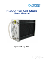
H-200 Fuel Cell Stack
User Manual
Updated 14 Aug. 2013
Mode No.: FCS-C200
Manual_FCS-C200_V2.0_EN
Disclaimer
This manual incorporates safety guidelines and recommendations. However, it is not intended to
cover all situations. It is the responsibility of the customer to meet all local safety requirements and
to ensure safety during operation, maintenance and storage of the H-200 stack.
Although all efforts have been made to ensure the accuracy and completeness of the information
contained in this document, Horizon reserves the right to change the information at any time and
assumes no liability for its accuracy.
Actions that will void the fuel cell and controller warranty:
●
●
●
●
●
●
●
Attempt, under any circumstance, to disassemble or inappropriately tamper with the fuel cell.
Operate the fuel cell with a controller not designed and built by Horizon for the specific fuel cell.
Operate the fuel cell with valves and blowers, that are not provided by Horizon for the specified fuel cell and controller.
Disassemble the fuel cell.
Disassemble the controller.
Operating the fuel cell and controller that is not in the setup and/or specified in the user manual provide for the specific product.
Operate the fuel cell stack without the controller produced by Horizon or with the controller not produced by Horizon.
Do not attempt, under any circumstance, to disassemble or
inappropriately tamper with the fuel cell. There will be no repair,
replace or refund should disassembly or tampering occur. If you have
questions or need help with regards to the fuel cell and its technology
please contact:
[email protected]
IMPORTANT
In order for the warranty to come into effect the stack must be registered on the Horizon
Warranty Page at: www.horizonfuelcell.com/warranty.htm
Manual_FCS-C200_V2.0_EN
Table of Contents
1. Safety............................................................................................... 1
2. Terminology...................................................................................... 6
3. Stack and System Component Information..................................... 10
4. Technical Specification..................................................................... 12
5. System Set-Up................................................................................. 13
6. System Set-up Diagram..................................................................... 20
7. Notes for the set up ......................................................................... 21
8. Operating Procedures....................................................................... 22
9. Performance Characteristics............................................................. 25
10. Storage and Re-Use........................................................................ 26
11. Trouble Shooting&System Checks.................................................. 27
12. Fuel Cell Drawing............................................................................ 31
13. FAQ................................................................................................. 32
Manual_FCS-C200_V2.0_EN
1. Safety
Please read all instructions carefully prior to product use and keep this manual for future reference.
The safety guidelines included here may not cover every situation. Use common sense.
1.1 General information
For this unit to generate electrical power, a supply of hydrogen fuel is necessary. It is important
for any operator to be aware of, understand, and follow all local safety requirements related to the
handling of hydrogen and compressed gases. Ensure that your facility conforms to all local regulatory
requirements, including building codes and recommendations.
The fuel cell system has built-in safeguards and is designed to shut down automatically if any outof-range operating condition occurs. Possible situations include low cell voltage, high current, high
temperature, low fuel pressure.
• Do not operate the stack on a grade of more than 65℃.
• Do not connect or disconnect power cables when the fuel cell stack is energised.
• Do not dismantle the system. Contact Horizon if you have any concerns about operation.
1.2 Using Hydrogen
WARNING! FIRE OR EXPLOSION
Keep all sources of ignition away from hydrogen.
This unit uses hydrogen fuel. Hydrogen is a colourless, odourless and flammable substance. It is
highly combustible in the presence of oxygen and burns with a colourless flame. Leaking gas may be hot and pose a burn danger. Stop the flow of gas – if you are not in danger –
and use water to cool the area. If fire occurs, do not attempt to extinguish flames, allow the fire to
burn out.
Prevent overexposure to hydrogen. Hydrogen is non-toxic but can act as a simple asphyxiant by
displacing the oxygen in the air. There are no warnings before unconsciousness results. When
operating the stack in an enclosure:
• Ensure ventilation slots are clear and unobstructed at all times during operation.
• Operate within the temperatures limits stated in the manual.
• Never operate if an alarm condition exists.
Note: We highly recommend customer use a hydrogen sensor(not provided) to detect the
hydrogen leakage.
Manual_FCS-C200_V2.0_EN
1
1.3 Handling Compressed Gas Cylinders
WARNING
Do not handle compressed hydrogen gas cylinders without training or experience.
• Use a pressure regulator to control the fuel inlet pressure to the system. • Do not alter the fitting on a regulator. Ask experienced personnel for help.
• Do not attempt to force gas cylinder threads.
• Never transport a gas cylinder with regulators attached. Ensure cylinder caps are in place. Always
use a cylinder cart with a safety strap or chain.
• Secure a high-pressure cylinder to a bench, post, or fixed object to avoid accidental contact.
• Avoid unnecessary contact with On/Off valves. They can easily move to “On” by accident.
1.4 Hydrogen Leakage
Hydrogen is colourless, odourless and tasteless. Hydrogen is non-toxic but can act as a simple
asphyxiant by displacing the oxygen in the air. There are no warning symptoms before unconsciousness
results.
WARNING
Inhaling hydrogen can lead to unconsciousness and asphyxiation. Hydrogen molecules are smaller
than any other gas, making hydrogen more difficult to contain. It can diffuse through many materials
considered airtight. Fuel lines, non-welded connections, and non-metal seals such as gaskets, O-rings,
pipe thread compounds and packings present potential leakage or permeation sites. Furthermore,
hydrogen’s small molecule size results in high buoyancy and diffusivity, so leaked hydrogen will rise and
become diluted quickly.
Constant exposure to hydrogen causes hydrogen embrittlement in many materials. The mechanisms
that cause hydrogen embrittlement effects are not well defined. Factors known to influence the rate and
severity of hydrogen embrittlement include hydrogen concentration, hydrogen pressure, temperature,
hydrogen purity, type of impurity, stress level, stress rate, metal composition, metal tensile strength,
grain size, microstructure and heat treatment history. Moisture content in the hydrogen gas may lead to
metal embrittlement through the acceleration of the formation of fatigue cracks. Hydrogen embrittlement
can lead to leakage or catastrophic failures in metal and non-metallic components.
As a preventative measure, the stack must be operated in a well-ventilated area in order to inhibit
potential hydrogen accumulation.
WARNING!
Always operate the stack in a well-ventilated area and ensure that ventilation slots are unobstructed.
Manual_FCS-C200_V2.0_EN
2
1.5 Flammability and volatility
Hydrogen is flammable over concentrations of 4 – 75% by volume in air, and is explosive over
concentrations of 15 – 59%. As a result, even small leaks of hydrogen have the potential to burn or
explode. Leaked hydrogen can concentrate in an enclosed environment, thereby increasing the risk of
combustion and explosion.
Hydrogen flames are pale blue and are almost invisible in daylight due to the absence of soot. Due to
its high buoyancy and diffusivity, burning hydrogen rises unlike gasoline, which spreads laterally.
A flammable or explosive hydrogen mixture is easily ignited by a spark or even a hot surface. The autoignition temperature of hydrogen is 500 °C (932 °F). The energy of a hydrogen gas explosion is 2.4
times that of gasoline or methane for an equal volume. Hydrogen gas explosions are therefore more
destructive and carry further.
WARNING!
A mixture of hydrogen and air is potentially flammable and explosive and can be ignited by a spark or a
hot surface.
As in the presence of any fuel, all sources of ignition, including smoking, are not permitted in the vicinity
of the stack.
WARNING!
Keep all sources of ignition away. Smoking is not permitted in the vicinity of the stack.
1.6 Oxygen Depletion
Oxygen is a colourless, odourless, non-toxic and tasteless gas. Oxygen is essential for life in
appropriate concentrations.
Ambient air contains up to 21% oxygen. Oxygen levels below 19.5% are biologically inactive and
may act as simple asphyxiants. Effects of oxygen deficiency may include: rapid breathing, diminished
mental alertness, impaired muscular coordination, faulty judgement, depression of all sensations,
emotional instability, and fatigue. As asphyxiation progresses, nausea, vomiting, prostration, and loss
of consciousness may result, eventually leading to convulsions, coma, and death. At concentrations
below 12%, immediate unconsciousness may occur with no prior warning symptoms.
WARNING!
Lack of oxygen can lead to unconsciousness and asphyxiation.
As a preventative measure, the stack must be operated in a well-ventilated area in order to compensate
for the oxygen used within the fuel cells.
WARNING!
Always operate the stack in a well-ventilated area.
Manual_FCS-C200_V2.0_EN
3
1.7 Electrical Safety
WARNING!
Avoid contact with an exposed fuel cell stack. Electrical shock can cause personal injury or death.
• Do not touch fuel cell plates or any electrical components at any time. A running fuel cell stack is a
potential electrical hazard that can cause burns or electrical shock.
• Do not wear metallic jewellery – rings, bracelets, watchbands, or necklaces – when you are close to
an exposed fuel cell stack.
• Minimise static discharge. If possible, ground all equipment.
• Minimise conductivity. Avoid contact with surfaces that are in contact with water or gases. Do not
operate or store in wet or damp conditions.
• Never use damaged extension cords.
The stack generates up to 38VDC (open circuit voltage). This voltage decreases as current is drawn
from the stack. The stack produces 24V at maximum power. This voltage is exposed at the output
power connections. These low voltages may constitute a shock hazard and can damage electronic
components if shorted. Therefore, do not touch individual fuel cells, cell voltage monitoring equipment
or electrical components.
WARNING!
Do not touch fuel cells, cell voltage monitoring equipment or electrical components. Electronic
components can also be damaged as the result of static discharge. To minimise this, ground all
equipment in contact with the stack. Never use damaged extension cords. Minimise conductivity by
avoiding surfaces in contact with water; hands and clothes must be dry. Do not operate or store the
stack in wet or damp conditions.
WARNING!
Minimise static discharge. Ground all equipment. Residual reactants within the stack can develop a
charge in a matter of minutes when turned off. A reading of zero volts across the entire stack does not
guarantee that all fuel cells are uncharged.
WARNING!
Always assume that the fuel cell stack is charged. Jewellery (such as rings, necklaces, bracelets and
watches) may concentrate an electric current when it comes into contact with charged components,
or when a shock passes through the human body. Accordingly, no jewellery should be worn near the
stack.
WARNING!
Do not wear jewellery near the stack.
No pungent odor, paint and perfume are allowed around stack.
Manual_FCS-C200_V2.0_EN
4
1.8 High Temperature
The fuel cell stack is designed to operate at 65ºC. At this operating temperature, the air exhaust stream
temperature can reach 55ºC and the cooling air stream can reach 17ºC above ambient conditions.
These temperatures are sufficient to cause burns or severe discomfort. Accordingly, avoid contact with
the fuel cell stack, or components that convey process or cooling air.
WARNING!
Avoid contact with the fuel cell stack or components that convey process or cooling air.
Manual_FCS-C200_V2.0_EN
5
2. Terminology
PEM fuel cell:
A PEM (Proton Exchange Membrane) fuel cell is a device that converts hydrogen and oxygen into
water and electricity.
A fuel cell stack:
It includes a plurality of plate-like fuel cells arranged along an axis generally parallel to cell
thickness with electrically conductive separator plates between each pair of cells.
Reactants:
Reactant is a material used to start a chemical reaction. In the fuel cell the reactants are air and
hydrogen by which the electricity will be generated.
Humidification:
Humidity that the fuel cells need for running.
Blower:
Supply air to the fuel cells and meanwhile decrease the temperature in the stack.
Purging valve:
For purging out the water and air gas redundant in the fuel cells.
SCU:
Short circuit unit – the short circuit will be controlled for good performance of the stack.
Mass flow per minute:
The total amount of the hydrogen flow through the fuel cell every minute, which the hydrogen
supply can be calculated.
HFCT:
Horizon Fuel Cell Technologies
Manual_FCS-C200_V2.0_EN
6
A
B
C
D
F
E
A: Warning labels
B: FC+ connector
C: FC- & load- connector
D: H2 supply valve
E: Controller multi-connector
F: H2 purge valve
Note: Pictures in the manual are only for reference, takes material object as the
standard.
Manual_FCS-C200_V2.0_EN
7
A
B
D
C
A: Horizon logo
B: H2 inlet connector
C: H2 outlet connector
D: Blower
Manual_FCS-C200_V2.0_EN
8
A
C
B
L
E
H
J
K
D
F
G
I
A: Horizon Logo
B: LED
C: Product No.Label
D: Connect plug
E: SCU(short circuit units) switch
F: ON/OFF button
G: Connect to FC+
H: Connect to FCI: Connect to Load+
J: Controller power supply DC 13V+
K: Controller power supply DC 13VL: LCD connector (optional LCD, not provided)
Manual_FCS-C200_V2.0_EN
9
3. Stack and System Component Information
1. Stack
Is made up of plate-like cells with air channels to allow
the flow of air across the membrane. The membrane
facilitates the flow of Hydrogen creating the release
of electrons. Electrically conductive separator plates
between each pair of cells enable the flow of electrons.
The stack aspect is that they are all placed on top of each
other and held together by epoxy endplates.
2. H2 Supply Valve
It controls the H2 input. When the controller turns on, also
the H2 supply valve does. When system turns off, it is in
the off position for preventing hydrogen leakage.
3. H2 Purge Valve
It purges out the water and air gas redundant in the fuel
cells. Please note that the plastic point is for input and
metal point for output.
4. Short Circuit Unit
It ensures best performance of the fuel cells.
5. On/Off Switch
Hold it for 2 seconds for either on or off operation.
6. Blower
Supply air to the fuel cells and meanwhile decrease the
temperature of the stack.
Manual_FCS-C200_V2.0_EN
10
7. Controller Connector
Connect the stack to the T-sensor/blower/purging valve/
input valve on the controller.
8. Controller
Controls the stack temperature, blowers, hydrogen input,
purging and short circuiting of the stack.
9. H2 Input/Output connectors
H2 OUT: connect the tube shown in 11 below.
H2 IN: connect the tube shown in 11 below.
10. Fuel Cell +/Fuel Cell- &Load- Connectors
FC+ of the controller is connected to the fuel cell positive
pole.
FC- of the controller is connected to the fuel cell negative
pole.
11. Tube for H2 Input and Output
The tube with 6mm outer diameter and 3mm inner
diameter is connected to the H2 IN as in 9 above and to
the input valve of the hydrogen source. H2 output tube
with 4mm outer diameter and 2mm inner diameter is
connected to the purging valve on one end and the H2
OUT the other.
Manual_FCS-C200_V2.0_EN
11
4. Technical Specification
Type of fuel cell
Number of cells
Rated Power
Performance
H2 Supply valve voltage
Purging valve voltage
Blower voltage
Reactants
External temperature
Max stack temperature
H2 Pressure
Hydrogen purity
Humidification
Cooling
Stack weight (with fan & casing)
Controller weight
Dimension
Flow rate at max output*
Start up time
Efficiency of stack
Low voltage shut down
Over current shut down
Over temperature shut down
External power supply**
PEM
40
200W
24V @ 8.3A
12V
12V
12V
Hydrogen and Air
5 to 30ºC
65ºC
0.45-0.55bar
≧99.995﹪ dry H2
self-humidified
Air (integrated cooling fan)
2230 grams(±50grams)
400 grams(±30grams)
11.8cm x 18.3cm x 9.4cm
2.6 L/min
≦30S at ambient temperature
40% @24V
20V
12A
65℃
13V (±1V), 5A
* The flow rate may change with the power output.
** System electronics need external power supply.
*** The Specification is subject to change without notice.
Manual_FCS-C200_V2.0_EN
12
5. System Set-Up
PLEASE READ CAREFULLY BEFORE STARTING
WARNINGS:
1. The tube between the hydrogen pressure regulator and the fuel cell gas input is required to be less
than 30cm. The inner diameter of the hydrogen supply tube is required to be more than 3mm. The input
pressure to the stack is required to be 0.45-0.55Bar .
2. Disconnect the hydrogen tube from the hydrogen inlet immediately after the fuel cell stack is shut down.
Since hydrogen gas can leak into the fuel cell and destroy the stack.
3. The stack must be standing on the clear plastic feet.
4. Make sure the dry Hydrogen gas to be used must be ≥99.995% purity.
5. Make sure you have purged the water out of the stack as much as possible before use if you injected
water into the stack. Using the fuel cell stack with too much water inside can irreparably damage it!
6. Do not vibrate the stack when it is in operation.
7. Keep the stack in ventilation when it is in operation.
8. The external power voltage is required to be 12-14V.
9. Keep the SCU always on. Only when it causes your load operating in difficulty, turn off the SCU.
10. The tube between stack output and purging valve is required to be less than 20cm. The tube
connected to the purging valve output is required to be less than 30cm. The inner diameter of the tube is
required to be more than 2mm.
STEP 1:
Connect the controller to the stack to get the blower, the temperature sensor, the hydrogen supply
valve and the purge valve under control. The finished connection is shown in 1B.
1B
1A
1
2
3
4
5
6
7
8
Controller connector
Wire colours Connector pin #
Periferals controlled
Yellow
#1 & #5
Hydrogen supply valve
Blue
#2 & #6
Hydrogen purge valve
Red and Black
#3 & #7
Blowers (Red= +ve, Black= -ve)
Red
#4 & #8
Temperature Sensor
Manual_FCS-C200_V2.0_EN
13
STEP2:
Connect the controller to the stack as the output power also should be under control. The finished
connection is shown in 2E.
2A
2C
2B
2D
2E
Manual_FCS-C200_V2.0_EN
14
STEP 3:
Keep the SCU (Short Circuit Unit) switch ON at “-” for usual use.
Warning: Some home appliances may not be suitable for this activation process. It may cause
damaging. you can shut off the short circuit by switching it to "O", but it will cause at least 20%
performance loss.
3A
STEP 4:
Connect the output of the hydrogen supply valve to the stack (pay attention to arrow marked on
the valve). The hydrogen supply valve will prevent damage to the stack from the hydrogen while
the stack is off. Pay attention to the direction of the connection of the Hydrogen supply valve. The
finished connection is shown in 4F.
4A
4B
4C
4D
Manual_FCS-C200_V2.0_EN
15
4E
4F
STEP 5:
Connect the stack to the purge valve through the filter for a longer runtime and a better
performance (5A-5G). If not, the gas out of stack may have a negative effect on the purge valve
after a long-time running. Connect the output of the purge valve to a place away from the stack in
case of the damage caused by the Hydrogen leakage.
5A
5C
Manual_FCS-C200_V2.0_EN
5B
5D
16
plastic point : input
metal point:output
5E
5F
5G
Note: The tube is required to be less than 20cm between stack output and purging valve.
The tube connected to the purging valve output is required to be less than 30cm. The
inner diameter of the required to be more than 2mm.
Manual_FCS-C200_V2.0_EN
17
STEP 6:
Check all the connection first and connect the load to the system, Load+ is linked to the "load+" at
the controller, Load- links to the "FC- and load-" in the stack shown in 6A
6A
STEP 7:
Direct the outlet tubing of the purge valve away from the fuel cell. Do not let the purged hydrogen go
back towards the fuel cell stack, this will damage the fuel cell.
Purged Hydrogen
Manual_FCS-C200_V2.0_EN
7A
Note: The tube is required to be less than 20cm between stack
output and purging valve. The tube connected to the purging valve
output is required to be less than 30cm. The inner diameter of the
tube is required to be more than 2mm.
18
STEP 8:
Connect the controller to a stabilized external power supply through the “13V DC” connectors (8A).
The external power supply is required to be 13V(±1V), <5A.
8A
STEP 9:
Connect the Hydrogen supply to the hydrogen supply valve, and make sure the hydrogen pressure
is between 0.45-0.55Bar.
Warning:The tube between the hydrogen pressure regulator and the fuel cell gas input is
required to be less than 30cm.The inner diameter of this tube is required to be more than
3mm. The input pressure to the stack is required to be 0.45-0.55Bar .
Make sure the dry Hydrogen gas to be used is ≥99.995% purity and no sulphuric composition or
other gases such as CO or CH4, and also no pungent odor, paint and perfume are allowed around
stack. They all can poison the fuel cell, reducing its performance dramatically.
STEP 10:
Check the following steps before starting the system:
1.
The connection between the hydrogen input valve and the hydrogen source.
2.
The connection between the hydrogen input valve and the stack intput.
3.
The connection between the stack outoput and the purging valve.
4.
The output tube of the purging valve is kept away from the stack.
5.
The 8pin plug connections between the stack and the controller.
6. The "FC+/-" connection between the stack and controller.
7.
The input hydrogen pressure is 0.45-0.55Bar.
8.
The external power is providing 12-14V.
9.
The load is below 200W.
The System is now setup and ready to be used
Manual_FCS-C200_V2.0_EN
19
6. System Setup Diagram
SCU: Short Circuit Unit
GND: Grounding
Manual_FCS-C200_V2.0_EN
20
7. Notes for the set-up
Note: The pictures below are only for reference.
Stack should be placed like this
position. Stand on the plastic feet.
The voltage of external power supply is
between 12V-14V, the current range is
different based on the different stack.
The tube is required to be less than 20cm between stack
output and purging valve. The tube connected to the purging
valve output is required to be less than 30cm. The inner
diameter of the tube is required to be more than 2mm.
Warning: The tube between the hydrogen pressure regulator
and the fuel cell gas input is required to be less than 30cm.
The pressure of the hydrogen is between
0.45--0.55Bar.
The load connecter, load+, is connected to
the "load +"in the controller. The load- is
connected to "FC- & Load-" in the stack.
Manual_FCS-C200_V2.0_EN
21
8. Operating Procedures
STARTUP PROCEDURE
Make sure both the stack and the ambient temperature are less than 45℃. Otherwise the system
will not start up successfully.
Hold the ON/OFF button down for 2 seconds to start the system; you will hear one beep, which
means the system has started.
If at this time the system shuts down in less than 1 second, then review the "beeping interpretation
during starting procedure" on page 28.
Once the system has started, you will hear a 3 seconds long purge from the purging valve, this is
the initial hydrogen going through the fuel cell to clear any non-Hydrogen gas from the system. If
you do not hear the hissing from the purge valve review “Checking the Valve” in Troubleshooting.
Following the purging the fuel cell will short circuit 5 times over a 1 minute period.
Manual_FCS-C200_V2.0_EN
22
RUNNING PROCEDURE
After system has started, depending on your setup and application you can change your load to get
the power you need within the specified power range for this fuel cell.
Don’t connect up a load that will demand more power than 200W which can permanently damage
the fuel cell.
During the operation, monitor the Hydrogen flow and pressure to consistently supply hydrogen at
0.45-0.55Bar.
Monitor the external power is 13V(±1V), <5A.
Direct the outlet tubing of the purge valve away the fuel cell. Do not let the purged hydrogen go
back towards the fuel cell stack, it will damage the fuel cell.
Pay attention to the purge, take care of the performance during the purge, If after each purge, the
performance is increased about 10%, it means you need to increase the pressure of hydrogen a
small amount. The fuel cell is flooding and so you need to use the pressure to push extra water out.
● Short circuit will happen every 10 seconds and last for 100ms everytime.
● If the load does not operate well with the short circuit on we recommend that you run the fuel cell for 10 minutes prior to switching the load on.
● There will be a slight decrease in the power provided to the load with the short circuit off.
Make sure the orientation of the fuel cell is kept the same during operation as shown on the fuel
cell stack with the sticker “This side up”.
Do not move the fuel cell around or shake vigorously during operation.
If the system shuts down during running procedure, review the Bleeping interpretation during
running procedure.
Manual_FCS-C200_V2.0_EN
23
SHUTDOWN PROCEDURE
To shut down the fuel cell system down, please follow these steps:
1. Turn off the load.
2. Hold the ON/OFF button down for 2 seconds to stop the system, you will hear one long beep,
which means the system is shutting down.
Note: When you turn off the on/off switch connected
to the control box at the temperature of the fuel cell
stack higher than 45˚C the stack will not stop working
immediately. Only when the stack temperature goes
down below 45˚C, the whole system will stop operation
in order to protect the stack. So in order to make it work
well, the fuel cell stack must be maintained lower than
45˚C before operate the on/off switch.
3. Turn the hydrogen supply off.
4. Disconnect the hydrogen supply tube from the hydrogen inlet as shown in the picture below.
WARNING:
Disconnect the hydrogen tube from the hydrogen inlet immediately after the fuel cell stack is shut down.
Since hydrogen gas can leak into the fuel cell and destroy the stack.
If the fuel cell is not in use, please follow these final steps.
Disconnect the external power supply from the controller.
Completely disconnect the fuel cell system from the load.
Completely disconnect the fuel cell system from the controller.
Let the fuel cell cool down before placing it into an air tight container. This will help to maintain its
performance particularly during long periods of storage.
Manual_FCS-C200_V2.0_EN
24
9. Performance Characteristics
Performance characteristics of the stack are presented. All performance data is given
for baseline operating conditions, defined at sea-level and room ambient temperature.
200W U-I Curve
40
35
Voltage(V)
30
25
20
15
10
5
0
0.0
1.0
2.0
3.0
4.0
5.0
6.0
Current(A)
7.0
8.0
9.0
10.0
H2 consumption(ml/min)
H2 consumption(ml/min)
2500
2000
1500
1000
500
0
0.0
50.0
100.0
150.0
200.0
250.0
Power(w)
200W Power Curve
250.0
Power(W)
200.0
150.0
100.0
50.0
0.0
0.0
1.0
2.0
3.0
4.0
5.0
6.0
7.0
8.0
9.0
10.0
Current(A)
Manual_FCS-C200_V2.0_EN
25
10. Storage and Re-Use
When finished operating the stack, place it in an enclosed area for storage to keep the stack from getting
too dry. The stack should be stored at room temperature.
If the stack is un-used for a long period of time (more than 4 weeks) and it's performance goes down 50%
to the rated power at 24V after 30 minutes operation, we recommend do the following steps.
Note: Generally, injecting water into the stack it is not recommended. Only if the performance of the stack
decreases 50% is it recommended to inject water into the stack to activate the stack before operation.
Rejuvenate by injecting water into the stack:
1.
Connect a short section of hosing to the gas port marked “H2 in”.
2.
Fill a syringe (not provided) with water (distilled or purified). Make sure there is no air in the syringe. And then connect it to the hose attached to the “H2 in” port.
3.
Inject distilled or purified water into the stack until you see water coming out of the “H2 out” port (see picture A below for reference). Keep the water inside the stack for about 2 minutes. Now disconnect the syringe with the tube, and leave the water in the stack.
4. Purged the water out of the stack as much as possible before use, say, it is not coming out of the output. Connect a short tube to the "H2 out" port. And connect the H2 supply (0.45-0.55Bar) to
the stack without a load attached, to purge the stack as much as possible (i.e. letting hydrogen flow
through the stack to remove water and other contaminants). Using the fuel cell stack with too much
water inside can irreparably damage it! Please see picture B below for reference. Make sure the
hydrogen supply pressure is 0.45-0.55Bar.
0.45-0.55Bar
WARNING:
A
B
1. Please make sure you have purged the water out of the stack as much as possible before use, say, it
is not coming out of the output if you injected water into the stack. Using the fuel cell stack with too much
water inside can irreparably damage it!
2. The tube between the hydrogen pressure regulator and the fuel cell gas input is required to be less
than 30cm.
3. The stack must be standing on the clear plastic feet.
Manual_FCS-C200_V2.0_EN
26
11. Trouble Shooting & system checks
Check the external power supply
The battery might not be operating correctly or in the case of a battery may not have any charge
left.
1.
Disconnect the external power source.
2.
Using a multimeter take a reading of the positive and negative connection points on the external power connectors to the controller.
3.
If the power is <12V (<24V in H-5000) then the power is not coming through to be able to power the controller, blowers and valves.
4.
Change or recharge your power supply and check the voltage that it meets the fuel cell voltage before connecting it up to the controller.
Check the SCU
1.
2.
During operation with the SCU on, the voltage of the fuel cell will drop for 100ms every 10 secs.
If the fuel cell voltage is not dropping then contact [email protected] with the diagnostic “SCU not operational” with the controller number.
If the stack is un-used for a long period of time (more than 4 weeks and performance goes
down 50% to the rated power at 28.8V after 30 minutes operation):
Rejuvenate by injecting water into the stack before use:
1.
Connect a short section of hosing to the gas port marked “H2 in”.
2.
Fill a syringe with water (distilled or purified). Make sure there is no air in the syringe. And then connect it to the hose attached to the “H2 in” port.
3.
Inject distilled or purified water into the stack until you see water coming out of the “H2 out” port. Keep the water inside the stack for about 2 minutes. Now disconnect the syringe with the tube, and leave the water in the stack.
4. Purged the water out of the stack
Connect a short tube to the "H2 out" port. And connect the H2 supply (0.45-0.55Bar) to the
stack without a load attached, to purge the stack as much as possible (i.e. letting hydrogen
flow through the stack to remove water and other contaminants). Using the fuel cell stack with
too much water inside can irreparably damage it! Make sure the hydrogen supply pressure is
0.45-0.55Bar. Please see Storage and Re-use.
WARNING:
Please make sure you have purged the water out of the stack as much as possible before use, say,
it is not coming out of the output if you injected water into the stack. Using the fuel cell stack with
too much water inside can irreparably damage it!
Manual_FCS-C200_V2.0_EN
27
Automatic Shutdown Bleeping interpretation during starting procedure
If the system shuts down before finishing the start up procedure then please refer to the following
bleeping interpretation:
If the system stops during the starting:
BleepsInterpretation Actions
1.
Low fuel cell open voltage protection i.e. the average cell voltage is <0.7V.
2.
High ambient temperature protection, the ambient temperature around the system is >45˚C.
3.
Low external power voltage protection i.e. external power is <12V.
Automatic Shutdown Bleeping interpretation during running procedure
If the system shuts down during operation within the product parameters then please refer to the
following bleeping interpretation:
BleepsInterpretation Action
1.
High current protection i.e. current is too high
- For H-100 - H-300 is > 12A set by the controller.
- For H-500 - H-1000 is > 30A set by the controller.
2.
High temperature fuel cell protection i.e. fuel cell is running >65˚C.
3.
Low voltage fuel cell protection i.e. the average voltage per cell is <0.5V
Note: If one of the above situations occurs, the stack will disconnect the load and make an
alarm. Reduce the demand of the load on the fuel cell. The system will re-connect the load every
10 seconds. If the situation causes the initial disconnection is the same, the system will again
disconnect the load.
Diagnosis
Potential for fuel cell damage?
“Fuel cell internal short circuit” - Yes
“Controller internal short circuit”
- Yes
“Controller reading too low voltage” - No
“Controller not operational” - Yes
“Supply valve not opening” - No
“Purge valve is not opening” - Yes
“Blower(s) not operational” - No
“LCD not operational” - No
“High current protection” - Yes
“High temperature fuel cell protection”
- Yes
“Low voltage fuel cell protection”
- Yes
“High ambient temperature protection”
- Yes
“Low external power voltage protection”
- No
“Temperature sensor resistance different” - Yes
Note: If the diagnosis refers to a "Yes" from the above list, shut down the system
immediately to avoid potential further damage to the fuel cell and contact support@
horizonfuelcell.com.
If the system shuts down by itself check the following details
1.
Make sure you have connected all wires according to the System Setup Diagram.
2.
Make sure the external voltage is 12V -14V.
3.
Make sure you have connected the hydrogen supply with the correct pressure.
4.
Make sure the load is below 200W. Overload can trigger the stack protection function to avoid the damage to the stack.
5.
Check whether the fuel cell temperature is below 65oC, the system will shut off if it is above 65oC.
Manual_FCS-C200_V2.0_EN
28
Checking the Fuel Cell System
-
If the fuel cell shuts down you need to check the voltage of the fuel cell by measuring
between the FC+ and FC- connectors on the fuel cell. There are 3 possible scenarios:
-
Voltage = 0
o
Check the supply valve and purge are open.
● If not open, see Checking Valves in trouble shooting.
● If open, check that the wire FC+ and FC- from the fuel cell controller are
connected the right way around to the fuel cell FC+ and FC- connectors, red-red and black-black.
● If wiring wrong, change it to be correct immediately, repetitive attempts at starting
the stack with this setup will permanently damage the stack.
● If wiring correct, disconnect the FC+ and FC- from the fuel cell controller and start
the fuel cell system again, it will shutdown automatically, following this measure the fuel cell voltage.
● If voltage is still = 0, the stack has short circuited internally and needs to be
changed. Contact [email protected] with the diagnostic “fuel cell internal short
circuit” with the fuel cell number.
● If voltage is >0, then the controller has a problem. Contact [email protected]
with the diagnostic “Controller internal short circuit” with the controller number.
-
Voltage <0.6 per cell
o
The fuel cell is dehydrated and needs re-hydrating. Follow the re-hydrating the fuel
cell Conditioning the fuel cell steps.
-
Voltage >0.6 per cell
o
The fuel cell itself is therefore fine and the fuel cell controller is reading the voltage wrong.
o
Check the various connection points between the fuel cell stack and the controller
are firmly in place.
o
Re-start the system. If the problem continues contact [email protected]
with the diagnostic “controller reading too low voltage” with the controller number.
Checking Valves
1.
With the system completely setup, Start the system.
2.
Once the system has started, you will hear a 3 seconds long purge from the purging valve,
this is the initial hydrogen going through the fuel cell to clear any non-Hydrogen gas from the
system. If you do not hear the hissing from the purge valve,
a)
Check the supply valve and purge valve are opening, this is can be done by:
i. Holding the valves during the starting up and feeling the clicking motion inside the
valves.
ii. Alternatively, apply the external power directly to each valve at 12V to feel and
hear the clicking of the valves opening.
iii. If either of the valves are not opening, then contact [email protected]
with the diagnostic “Supply valve is not opening” and/or “Purge valve is not opening” with the fuel
cell number.
3.
If the valves are opening, check before starting the system again:
a)
The 8pins plug connector is firmly clicked together.
b)
The hydrogen supply:
i. Is open.
ii. Input pressure is 0.45-0.55Bar.
4.
If both valves open, system will follow normal start up procedures.
5.
If either of the valves still don’t open. Check the controller section on Valves in Trouble
shooting.
Manual_FCS-C200_V2.0_EN
29
Check the Blowers
1.
With the system completely setup, Start the system.
2.
Once the system has started, after the fuel cell system has been short circuited 5 times as
part of the startup procedure the blowers will start to turn, pulling air through the fuel cell.
a)
If all the blower(s) are creating non-standard noise, turning slowly, or not turning at all.
i. Check carefully that there are no obstructions in the blower(s).
ii. Carefully spin the blowers using your finger make sure there is rotation movement,
without obstructions.
iii. The electrical supply from the controller needs to be checked, by applying
the 12V/24V external power supply directly to the 8pin plug connector points for the fans and
monitoring the performance of the blowers.
iv. If the blowers are not running or running slowly and the current is very high, then
contact [email protected] with the diagnostic “Blower(s) not operational” with the fuel
cell number.
v. If the blower(s) are running fine. Check the controller section on Blowers in
Trouble Shooting.
Check the controller
1.
Make sure the system is shut down and the hydrogen supply is off.
a)
Disconnect the Fuel cell stack from the controller.
b)
To check that the controller is operating correctly, review the pin connector drawing
against the pin connector.
c)
Using a multimeter you can check the power being supplied to each of the
peripherals (solenoid valve, purging valve, blowers) of the fuel cell.
i. With the external power supply connected to the controller and the fuel cell not
connected to the controller, start the system up.
ii. The controller will run through the start-up procedure supplying power to the
peripherals.
iii. By checking each pair of pins you will get the following power readings:
Wire colours
Blue
Yellow
Red
Red and Black
Connector pin #
Connected Peripherals
Voltage supplied
#1 & #5
Hydrogen purge valve
12V for 3 seconds
#2 & #6
Hydrogen supply valve
12V constant
#4 & #8
Temperature Sensor
0V
#3 & #7
Blowers (Red= +ve, Black= -ve) after 3 seconds 3V constant
iv. If any of the pins are not supply the voltage then contact [email protected]
with the diagnostic “Controller not operational” with the controller number and the voltage readings
you are getting from the connector point.
d)
To check the Control chip
i. The system does not need to be started for this.
ii. Connect the multimeter to the fuel cell stack 8 pin connector, pins #4 & #8.
iii. The resistance should be 1076ohms at 20˚C (±3.8ohms for every ±1˚C) of the
fuel cell temperature.
iv. If resistance reading is different then contact [email protected]
with the diagnostic “Temperature Sensor resistance different” with the fuel cell number and the
resistance readings you are getting from the connector point.
e)
Check your external power supply, to see how much current is being drawn during
the starting time, it should be more than 0.6A for 3 seconds.Check the external power supply
Manual_FCS-C200_V2.0_EN
30
12. FUEL CELL DRAWING
Manual_FCS-C200_V2.0_EN
31
13. FAQ
What is the SCU?
This is the Short Circuit Unit, it helps to condition the fuel cell for long term good performance.
What is the Hydrogen pressure supplied to the fuel cell stack?
The pressure is required to be 0.45-0.55Bar.
What is the maintenance of the stacks?
1. When the stack finishes operation, disconnect the hydrogen input and output tube from the stack
and also disconnect the power output. Use a tube to connect the hydrogen input to the hydrogen
output of the stack.
2. Store the stack in ambient temperature and in a closed space. Keep it away from toxic gas, such
as So2, H2S, Co.
3. Operate the stack for 2-3 hours every 2 weeks or at least one month in order to maintain the
stability of the stack performance.
4. If the stack has not been used for more than 2 months, the stack power maybe get a little bit
down when you use it again. We suggest at the beginning not to have full load to the stack, try
to have half power for the starting. And then step by step increase to full load, try to increase 5%
every 10 minutes. After this activation process, the stack can reach the rated power within 1-2
hours.
5. If the stack has not been used for more than 2 months and your load could be set to constant
voltage, try to operate the stack under 0.6V/cell. Under this operation mode, the stack can reach
the rated performance within 1-2 hours.
Manual_FCS-C200_V2.0_EN
32