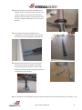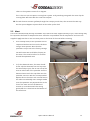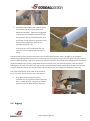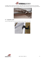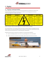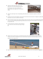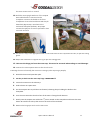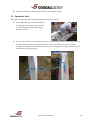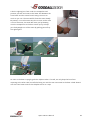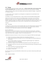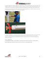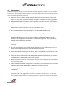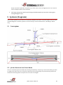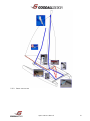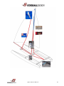
1
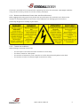
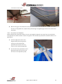
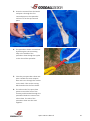
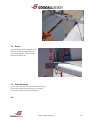
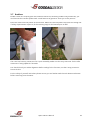
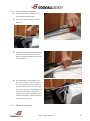
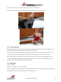
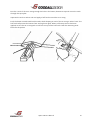
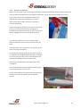
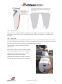
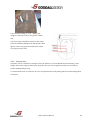
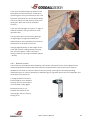
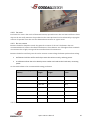
Contents 1 Introduction ................................................................................................................................................... 4 1.1 About this Owner’s Manual .................................................................................................................... 4 1.2 General information ............................................................................................................................... 5 1.2.1 Loading Advice ................................................................................................................................ 5 1.2.2 Opening the Hull ............................................................................................................................. 5 1.2.3 Stability, Capsize and Recovery ....................................................................................................... 5 1.2.4 Danger from Overhead Power Lines and Other Obstacles ............................................................. 6 1.2.5 Towing on the Water ...................................................................................................................... 6 2 3 Assembly ....................................................................................................................................................... 7 2.1 Glossary .................................................................................................................................................. 7 2.2 Tools needed ........................................................................................................................................... 8 2.3 Arrival of goods....................................................................................................................................... 8 2.4 Platform .................................................................................................................................................. 8 2.5 Mast...................................................................................................................................................... 14 2.6 15 2.7 Rigging .................................................................................................................................................. 15 2.8 Spinnaker pole ...................................................................................................................................... 16 Rigging ......................................................................................................................................................... 17 3.1 Raising / Lowering the Mast ................................................................................................................. 17 3.2 Spinnaker Pole ...................................................................................................................................... 20 3.3 Spinnaker System.................................................................................................................................. 21 3.3.1 Before Raising the Mast ................................................................................................................ 22 3.3.2 After raising the mast .................................................................................................................... 22 3.3.3 Tack line ........................................................................................................................................ 23 3.3.4 Attaching the Spinnaker ................................................................................................................ 25 3.4 Boom..................................................................................................................................................... 27 3.5 Mast Rotation ....................................................................................................................................... 27 3.6 27 3.7 Rudders ................................................................................................................................................. 28 3.7.1 Locking Down the Rudders ............................................................................................................ 29 3.7.2 Releasing the Rudders ................................................................................................................... 29 3.8 Centerboards ........................................................................................................................................ 30 3.9 Mainsail ................................................................................................................................................ 30 3.9.1 Battens .......................................................................................................................................... 30 3.9.2 Raising the Mainsail ...................................................................................................................... 32 Viper Owner's Manual 2 3.9.3 Lowering the Mainsail ................................................................................................................... 34 3.10 Jib .......................................................................................................................................................... 34 3.10.1 Jib Sheet ........................................................................................................................................ 34 3.10.2 Jib Downhaul ................................................................................................................................. 35 3.10.3 Raising the Jib ................................................................................................................................ 35 4 Sailing .......................................................................................................................................................... 37 4.1 Launching ............................................................................................................................................. 37 4.2 Recovery ............................................................................................................................................... 37 4.3 Towing on the Water ............................................................................................................................ 39 4.4 Tuning ................................................................................................................................................... 40 4.4.1 Platform......................................................................................................................................... 40 4.4.2 Rudder alignment .......................................................................................................................... 40 4.4.3 Noisy Foils ..................................................................................................................................... 41 4.4.4 Rig Tension .................................................................................................................................... 42 4.4.5 Mast rake ...................................................................................................................................... 42 4.4.6 Spreader rake ................................................................................................................................ 43 4.4.7 Diamond tension ........................................................................................................................... 44 4.4.8 Pre-bend ........................................................................................................................................ 45 4.4.9 Batten tension ............................................................................................................................... 45 4.4.10 45 4.4.11 General settings ............................................................................................................................ 46 4.5 5 Maintenance......................................................................................................................................... 48 Systems (Diagrams) ..................................................................................................................................... 49 5.1 Cunningham ......................................................................................................................................... 49 5.2 Jib line Retrieval into Front Beam ......................................................................................................... 49 5.2.1 50 5.3 Spinnaker Halyard ................................................................................................................................ 50 5.3.1 Duel line system (With Tack Line) ................................................................................................. 50 5.3.2 Single line system .......................................................................................................................... 51 5.3.3 Under Tramp Shock Cord Layout .................................................................................................. 53 6 Warranty ..................................................................................................................................................... 54 6.1 The Full Warranty Period ...................................................................................................................... 54 6.2 Warranty conditions ............................................................................................................................. 54 6.3 Exclusions.............................................................................................................................................. 54 6.4 Operation Limitations ........................................................................................................................... 55 6.5 Limitations ............................................................................................................................................ 55 6.6 Responsibilities ..................................................................................................................................... 55 6.7 Voided Warranty .................................................................................................................................. 55 Viper Owner's Manual 3 1 Introduction Congratulations on purchasing your new GOODALL VIPER. The VIPER is the next generation of 16 foot racing catamarans and you will soon see why. The speed and performance of the VIPER exceeds that of the bigger catamarans. The VIPER set new standards around the world in what a “little” boat can achieve. Greg Goodall Managing Director Australian High Performance Catamarans Pty. Ltd. 1.1 About this Owner’s Manual This manual has been compiled to help you set up and operate your VIPER catamaran safely and easily. It contains details of the boat and its fitted equipment. Please read it carefully and familiarize yourself with it and the boat before rigging and sailing. You have purchased a high performance racing catamaran and as such you should ensure that you are able to handle the catamaran in the anticipated wind and sea conditions. This owner’s manual is not a course on boating safety or seamanship. If this is your first beach catamaran, or if your unfamiliar with it, please ensure you obtain handling experience before “assuming command” of the boat. Your dealer, National Sailing Federation or Yacht Club will be pleased to advise you of local sailing schools, or competent instructors. Buoyancy aids are required for all racing events and are recommended to wear at all times by all crew. In some countries, a driving license or authorization may be required, or specific regulations might apply. Please familiarize yourself with these. This craft has been classified (in Australia) as a category C vessel, meaning a boat designed to operate in winds up to Beaufort force 6 scale and associated wave heights. Always maintain your boat properly and make allowance for the deterioration that will occur in time and as a result of use. Any boat, however strong it may be, can be severely damaged if not used properly. Please read this manual and familiarize yourself with all aspects of maintenance and care for your boat. Please keep this owner’s manual in a safe place and hand it over to the new owner when you sell the boat. Viper Owner's Manual 4 1.2 General information Manufacturer: Australian High Performance Catamarans Pty. Ltd. (GOODALL) Model: VIPER Category C: “A boat designed to operate on winds up to force 6 on the Beaufort scale and associated wave heights (significant waves up to 2 meters) Such conditions may be encountered on exposed inland water, in estuaries and in coastal waters in moderate weather conditions. A significant wave height is the mean height of the highest one third of the wave, which approximately corresponds to the wave height estimated by an experienced observer. Some waves will be double this height.” Specifications: Length (LH1) = 5.0 m (16.4 ft) Width (BH1) = 2.5 m (8.2 ft) Mast height = 8.5 m (28 ft) 2 2 Main sail area = 15 m (162 ft ) 2 2 Jib area = 3.7 m (40 ft ) 2 2 Spinnaker area = 17.5 m (188 ft ) Maximum draft = 1.25 m with centre boards down Maximum draft = 0.25 m with centre boards and rudders up Weight fully rigged = Sloop 129 kg (284 lb) Uni 125 kg (275 lb) Identification: Hull identification number (HIN) on stern of each hull. Sail numbers are not always indicative of this. 1.2.1 LOADING ADVICE Keep the total weight of provisions, persons and miscellaneous equipment not supplied by the manufacturer aboard below the Maximum Recommended Load and suitably distributed. Maximum Recommended Load: x 2 + + luggage = 200 kg. 1.2.2 OPENING THE HULL Hatch covers in the aft deck must be sealed before leaving the shore. When storing the boat ashore, be sure to have the holes covered but leave the hatches open for ventilation purposes. 1.2.3 STABILITY , CAPSIZE AND RECOVERY Viper Owner's Manual 5 This boat is intended to be recovered after capsize by the crew. The minimum crew weight needed is 70 kg. See the recovery section for correct recovery technique. 1.2.4 DANGER FROM OVERHEAD POWER LINES AND OTHER OBSTACLES When rigging and moving your boat, please look up and inspect the overhead area. Observe the location of overhead power lines and trees. These obstacles can damage your boat and are potentially dangerous or deadly to yourselves. 1.2.5 TOWING ON THE WATER When towing is required, ensure that: - The tow rope is secured around the mast base or mast step. The boat is towed at a low speed. The tow line is fastened in such a way that it can be released quickly when under load. The tow line is to be of sufficient length to maneuver safely. Viper Owner's Manual 6 2 Assembly All GOODALL boats require minimal assembly; all parts are rigged in the factory and come almost fully assembled so that you can be on the water as soon as possible. Should your boat have come through a local dealer, most of the assembly has probably already been done for you, but take this manual as a reference for building up and dismantling your VIPER when transporting and storing. 2.1 Glossary Aft: Back of the boat Bow: Front of the boat Batten: Thin rod which fits into a long narrow pocket in the sail Bridle wire: One of the two wires connected to the bow and forestay Boom: Spar at the foot of the sail Centre board (Dagger Board): A retractable plate that slides vertically into each hull Cleat: Fitting used for holding / securing ropes Clew: Lower most after-most corner of a sail Crossbar (Tiller): Bar that connects the rudder arms Dolphin striker: Load bearing strap under the front beam Downhaul (Cunningham): Control line to stretch the luff of the sail Foot: Bottom edge of the sail Forestay: Front wire supporting the mast Gunwale: Top outermost edge of the hull Goose neck: A hinge fitting connecting the boom to the mast Halyard: Rope or wire used to hoist or lower a sail Head: The top corner of the sail Hound: Point where the stays are connected to the mast Jib: Front sail Jib Sheet: Control line for jib tension Leeward: The side of the boat the sails are set to when sailing Leech: Trailing edge of the sail Luff: Front edge of the sail Main sheet: Rope controlling the tension of the main sail Mast rake: Angle of the mast from vertical Mast step: Fitting where the mast is connected to the front beam Viper Owner's Manual 7 Pintle: Fitting on the transom to attach the rudder Rudder stock: housing of a rudder blade Shackle: U-shaped metal strip with a pin to secure halyards etc Shrouds (Side stay): Wire supporting the mast sideways Spinnaker: Isometric sail hoisted when sailing downwind Spinnaker pole: the pole between the hulls used to fly the spinnaker Spreaders (Diamond): Metal struts placed in pairs to support the mast control the bend in the mast Stamaster: Adjustable side stay connectors Stern: Back of the boat Tack: Forward lower corner of the sail Tiller (extension): Steering stick connected to the tiller crossbar Traveler (Car): Runs on the traveler track, which the main sheet is attached Traveler (Track): Runs side to side on the rear beam Transom: Flat vertical plane of the end of the hull Trapeze: Wire to extend the body beyond the gunwale while sailing Windward: The side of the boat opposite to where the sails are set to when sailing 2.2 Tools needed Your VIPER parts will come from the factory pre-rigged so that it can be assembled easily, quickly and without an expensive tool kit, but be advised to have ready with you the following tools: - Sharp knife Cross head screw driver - Philips #2 7 mm ring spanner 17 mm ring spanner or preferably a hexagonal socket 24 mm open spanner Torque wrench (optional) Shackle tool Tape measure Duralac sealant (anti corrosive paste) 2.3 Arrival of goods A typical delivery would typically consist of 4 packages - 2 Long card board boxes each containing a hull. 1 Shorter cardboard box containing the beams, sail, boom, foils, rudder stocks etc. 1 Single long package for the mast, depending on shipment this may be a steel crate. 2.4 Platform Viper Owner's Manual 8 1. Place the 2 cardboard boxes that contain the hulls parallel on a flat surface approximately 2 meters apart and carefully cut the top open. The sides of the boxes may be folded down to provide a clean and protective working surface. The packing frames inside the box should keep the hulls upright while you work. 2. The beams will come from the factory prerigged and ready to go onto the boat. The shorter bolts and smaller washers are for the outer locations and the longer bolts and bigger washers for the inner locations. To access the outer bolt holes you will have to remove the plastic end caps from the beams with a Phillips head screwdriver, don’t undo any of the shock cords on the front beam as they are already in the correct position. 3. Wipe all dirt and grease from the beam pad before sitting the beam on. Make sure the beams are facing the correct way. The rear beam should have the traveler saddles facing backwards. Apply grease to the threaded part of all bolts before inserting them into the hull. Get all the bolts started before tightening any of the bolts. We recommend beginning with the inner front beam bolt. If a particular bolt is being difficult to fit. Release all the beam bolts and fit this bolt first. 4. Use a 17 mm hexagonal socket or spanner to tighten the bolts properly. The bolts should be set to 20Nm using a torque wrench. Check the bolts regularly but in never exceed the recommended 20 Nm. Viper Owner's Manual 9 Viper Owner's Manual 10 5. To reduce the risk of any sharp edges inside the hull tracks cutting the tramp, use a small piece of rod wrapped in sand paper (120 grit or less) and slide the length of the track and back to sand the inside edge of it. 6. The tramp should be pre-fitted to the front beam at the factory. If not remove the end plate from the front beam and slide the trampoline into the front beam groove refitting the end plate once the tramp is in place. 7. Loosen all beam bolts 2 turns; fully remove the beam bolts from one end of the front beam and allow the bows to move closer together. 8. Insert the bolt ropes on either side into the track of the hull. Carefully slide the trampoline down the track on each hull. This is best done with 1 person on either side of the platform keeping it even on each side. It is recommended you have someone feed the tramp into the track while another person pulls the tramp on. Viper Owner's Manual 11 9. Refit the beam bolts that were removed in nd step 7. You will require a 2 person to push the bows apart to achieve this. Then tighten the remaining bolts to 20 N/m. 10. Slide the alloy tube into the pocket at the rear end. Use the 3mm cord to lace the tramp to the rope buttons on the rear beam as per the picture. By starting at one side, tighten the lacing as much as possible and tie at the other end. All cords and bungees will be pre-fitted at the factory. Refer to the systems section of this document for diagram. 11. Attach halyard retrieval pulleys to the lacing before the second button in on each side. Viper Owner's Manual 12 12. After the platform has been assembled, the dolphin striker will need to be tensioned. Use a 24mm spanner to extend the striker post between the front beam and the striker strap. The front beam should bow up in the centre (10mm). 13. Toe straps have been provided on the trampoline. Tie the toe straps to the saddles on the rear beam and tighten to preference. 14. Remove the bottom half of the Stamasters from the side stays and attach to the side chain plates with the locknut on the inside and the control line loop facing forward (to be used with any control line). 15. The Continuous Cunningham system should have been already threaded from your dealer, if not, Viper Owner's Manual 13 refers to the Systems section for a diagram. This is also an “out to trapeze” cunning ham system. So by attaching using with the sister clip the cunning ham will come with the crew onto trapeze. 16. Thread the mast rotation (yellow) through the tramp eye and cleat, then around the side stay. Use the spare skippers trapeze shock cord to take up the slack 2.5 Mast Your mast should already be fully assembled. If the mast has been shipped directly to you, some fittings may be required to be fitted to complete the mast. All holes are predrilled and all components and rivets are supplied. Apply Duralac or anti corrosive paste on the head of the rivet before inserting. If not already fitted, fit the spreader to their respective brackets and secure the locknuts using a 7mm spanner. Note that the spreaders are pre set to the factory settings. You will notice two small dabs of epoxy on the wires. This must be left on for reasons that will be explained soon. To fit the diamond wires, the mast should lie flat. Clip the diamond arm end cap onto the wire and put your feet at one side of the mast at either side of the spreader. Pull the diamond wire until it the cap slides into the spreader. Secure it with the screw provided. Repeat this on the other side. You will notice this takes considerably more strength. Make sure the spreaders are perpendicular to the face of the mast and set the diamond tension (in accordance with the tuning guide) with the 17mm bolt at the bottom of the mast base. Viper Owner's Manual 14 All diamond wires will have a dab of epoxy on the diamond wires both above and below the spreader. TAPE is not suggested as it decays in the weather and easily slips. This prevents the spreader being knocked out of line during capsize or spinnaker hoist where the halyard wraps around the spreader and pulls it up. If the arms are out of alignment this can case the arm to collapse and the mast to break. The wires will be even from the factory but you should check that the mast is straight in the sideways direction by sighting down the sail track. If the mast has a bend this means that one diamond wire is tighter than the other and they need to be made even. Determine which wire needs to be tightened and releasing it from the diamond arm and the tang towards the top of the mast. Twist the whole wire clock wise while looking from the top of the mast; this will turn the small threaded swage inside the mast base and shorten the wire. Refit the wire to the tang and diamond arm and check for straightness. Repeat if necessary. The mast base should never have to be removed, but if, for some reason it does, this is the process. Unfit both diamond wires from the spreader arm and undo the mast base bolts with a 10mm spanner. The base and brass diamond adjuster block will just slide out. 2.6 Rigging Viper Owner's Manual 15 All rigging is fully assembled at the factory; it will simply need to be attached to the mast. The trapeze wires attach to the upper hole on the hound fitting. The side and forestay attach to the larger lower hole. 2.7 Spinnaker pole Attach the spinnaker chute to the pole with the Velcro straps on the chute. Viper Owner's Manual 16 3 Rigging 3.1 Raising / Lowering the Mast When rigging and moving your boat, please look up and inspect the overhead area. Observe the location of overhead power lines and trees. These obstacles can damage your boat and are potentially dangerous or deadly to yourselves. Before raising the mast you should organize your Spinnaker halyard, see below. The usual procedure is to raise the mast from the back of the boat, however the hinged mast step allows the mast to be raised and lowered from any direction. The key to this is that the front of the mast must face the direction that it is to be raised from, or lowered to. Raising the mast requires a minimum of 2 people. The usual procedure would be: 1. Put the assembled platform on a flat surface, preferably with its sterns windward. 2. Position the mast on the boat, sail track down, with the top of the mast out the stern. Viper Owner's Manual 17 3. Connect the side stays and for stays to the lower hole on the hound fitting ensuring that the forestay is in the center. Connect the Trapeze wires to the upper hole on the hound fitting. 4. Connect the side stays to the corresponding chain plates, with the Stamaster adjusters at maximum length. 5. Untangle and connect the skippers’ trapeze wire to the shock cord on the deck. The skippers’ Trapeze will be the outer most on the shackle at the hound. 6. Run the Spinnaker halyard up through the halyard cleat and up the mast to the top halyard block (passing in front of the hound fitting). Bring the halyard back down and tie off to the mast base for connection to the Spinnaker later. 7. Turn the mast over, sail track up, and connect the base of the mast to the mast step using the hinge pin. 8. Walk the mast up from the stern, you will need to step onto the trap or pass the mast to a 3 rd person already on the deck to complete this. At the same time the 2nd person should be pulling the mast up using one of the trapeze wires. 9. When the mast is vertical allow the mast to rotate so that sail groove now faces backwards. DO NOT let Viper Owner's Manual 18 the mast rotate until it is vertical. 10. Hold the mast upright with one of the trapeze wires while bridle is connected to the chainplate. Connect the bridal to the front chainplates. Ensure the bridal wire with the jib downhaul (Dyneema) is attached to the starboard chainplate (bellow). Wrap tape around the split pins to ensure spinnaker dose not catch and tear. 11. Set the fore stay to the appropriate hole on the bridle tube for the required mast rake, as per the tuning guide. 12. Adjust the Stamasters to tighten the rig as per the tuning guide. 13. Take out the hinge pin from the mast step. This must be removed when sailing to avoid damage. 14. Connect the crew trapeze wires to their shock cords. Lowering the mast is basically the reverse as raising it (also requiring 2 people): 1. Detach the boom and spinnaker pole. 2. Put the pin back into the mast step hinge. IMPORTANT!!!! 3. Loosen the tension on the side stays. 4. Undo at least on trapeze wire. 5. Use that trapeze wire to pull the mast forward, releasing the pin holding the bridle to the chianplate. 6. Turn the mast around so that the front of the mast is facing the aft direction 7. Gently ease the trapeze wire while the 2nd person stands on the trampoline and lowers the mast down. Be careful not to drop the mast on the track of the rear beam. 8. Remove the hinge pin and turn the mast over Viper Owner's Manual 19 9. Undo the remaining trapeze wires and take the Stamasters apart. 3.2 Spinnaker Pole Setting up the spinnaker pole is done after the mast has been raised. 1. Fit the spinnaker pole to the front beam using the pin and retainer clip. The pole must be supported by the bridle loop while this is done. 2. Assure that the knots on both bow braces are the same length. Connect the front braces to the bow by passing a loop through the hole in the bow and then pass the knotted tail through the loop on the outside to prevent the loop coming back through. Work this firm so it will not move during sailing. Viper Owner's Manual 20 3. Adjust the bridle loop so that there is a small amount of pre-bend in the spinnaker pole. 4. Tie the 2mm cord from the ring to port bridle chain plate as this will support the ring while hoisting and dropping and limits spinnaker fouling. 5. Connect the 2 shock cords at the end of the chute to the loops under the trampoline. This should keep the chute taught. These pass UNDER the Cunningham lines. 3.3 Spinnaker System Viper Owner's Manual 21 Running the halyards and organizing the spinnaker system is usually done before the mast is raised. Setting up the pole and attaching the spinnaker is done after the mast has been raised. 3.3.1 BEFORE RAISING THE MAST 1. Take the tapered halyard and pass the Dyneema end through the hoisting cleat and up to the hoisting block near the top of the mast passing through any anti foul loops on the way. Make sure the halyard passes in front of all shroud wires and on the port side of the forestay at the hound fitting. 2. Take the Dyneema end and tie it to the mast spanner and cleat the other end into the hoisting cleat, this will stop it falling out while raising the mast. 3.3.2 AFTER RAISING THE MAST 3.3.2.1 H ALYARD 1. Pass the retrieval end through the beam saddle, back to the take-up pulley on the tramp. Pass it forward trough the retrieval block and pass it through the hole in the tramp. Viper Owner's Manual 22 2. Pass the retrieval line trough the eyelet in the bottom of the chute and use the tiller extension to pull it up and out by poking the extension down and tying the line to it. 3. Tie the retrieval line the bridal until you are ready to attach the spinnaker. 4. Before racing you should be sure that the reinforced area of the halyard is in the cleat when the spinnaker is hoisted, adjust this by shortening or lengthening the knot at the head of the spinnaker. The reinforcement on the halyard is near the taper where the halyard feels extra thick. 3.3.3 TACK LINE The tack line will be already threaded into your spinnaker pole for you. Once the pole is fully attached to the boat the tack line maybe threaded as follows Viper Owner's Manual 23 1. Take the tack line from where it exits the spinnaker pole and pass it around the cheek block on the bottom on the beam. Then, in this order, pass it trough the trip line thimble, the cam cleat and the restraining saddle. This should all pass underneath all of the cunning ham lines. 2. Pass the line between the tramp and hull to the turning pulley on the outside of the beam and then pass it through the eyelet in the tramp. 3. On the underside of the tramp, pass the tack line trough the pulley on the spinnaker retrieval shock cord and finish by tying it off at starboard righting rope saddle on the main beam. These lines should pass on top Viper Owner's Manual 24 of all other shock cords. 4. Before racing you should be sure that the reinforced area of the tack line is in the cleat when the tack is fully pulled out, adjust this by shortening or lengthening the knot at the tack of the spinnaker. 3.3.4 ATTACHING THE SPINNAKER When attaching the spinnaker make sure it is not tangled or twisted. You may hoist, or partly hoist the spinnaker on land to make it easier to organize. This should only be done in sheltered areas or in light winds. 1. Untie the Dyneema end of the halyard from the mast spanner and tie it to the head of the spinnaker but ensure the runs clearly to the top hoisting pulley. 2. Tie the tack of the spinnaker to the Dyneema end of the tack line (at the front of the spinnaker pole). Viper Owner's Manual 25 3. Untie the retrieval from the bridal and pass it through the first retrieval point on the spinnaker and tie it off at the top retrieval point. 4. The spinnaker sheets are attached by hitching the red connecting loop in the middle of the spinnaker sheet though the eyelet in the clew of the spinnaker. 5. Take the port spinnaker sheet and pass it inside the crew’s trapeze wire and run it through the ratchet on the deck. Then to the turning block attached to the front beam. 6. The other end of the spin sheet passes around the front of the forestay and threaded through the spinnaker blocks the same as the other sheet. The tails of the spinnaker sheet are then tied together. Viper Owner's Manual 26 3.4 Boom Insert the block onto the goose neck and put the pin through the holes, from top to bottom. Secure the pin with the retaining clip. 3.5 Mast Rotation Tie the quick release line to the control line pulley that comes from the center hole in the tramp; ensure the stopper ball covers this knot. 3.6 Viper Owner's Manual 27 3.7 Rudders Rudder stocks are uniquely port and starboard. When first attaching rudders they will be stiff, you can lubricate the transom pintles with a small amount of grease to assist you in this process. Place the stocks onto the pintles at the transom. Make sure the lock plates snap over the casting and if safety requirements require it, fit the retaining rings on the bottom pins as well. The cross bar has easy connectors for a quick assembly. Make sure the easy connector for the tiller extension is facing upwards / forwards. You should check you rudder alignment before sailing for the first time, see the Tuning section on how to do this. For the safety of yourself and others please ensure you are familiar with the Lock down mechanism before venturing onto the water. Viper Owner's Manual 28 3.7.1 LOCKING DOWN THE RUDDERS 1. Lift the lock down rod to release it from plastic lockup keeper. 2. Push the rudder to the fully down position. 3. Align the lockdown pin with the hole and squeeze the end of the lock down rod and the tiller arm to press it into position. 4. The lockdown rod should be set to the correct length from the factory. If for any reason you have to adjust it, simply undo the lock nut and rotate the rod to shorten or lengthen it. The rod should be under a medium amount of compression when in the lockdown position, such that there is a small bow in the rod. 3.7.2 RELEASING THE RUDDERS Viper Owner's Manual 29 Lift the middle of the rod to release the pin from the lockdown hole. Raise the rudder. Press the lock down pin and rod into the plastic lock up keeper. 3.8 Centerboards Both centerboards are the same, but the strap fitted to them makes them port and starboard. The straps should have the retainer knot on the outside of the boat. The strap connecting the centerboards should pass under the toe straps and all other lines on the tramp deck. When sailing, pulling the strap will raise the board from either side of the boat. Before putting the centerboards in their casing, rinse the board and the felt lining with water to remove sand and grit that might damage the board. Make sure to keep the centerboards in their protective covers during transportation and storage. 3.9 Mainsail 3.9.1 BATTENS Battens are numbered 1-7, top to bottom. Roll the main sail out on a flat surface an slide the battens in their corresponding sleeves. Make sure the tapered end fits nicely into the plastic batten pocket ends. Viper Owner's Manual 30 Run the 2 ends of the tie in strings trough the hole in the batten, bottom to top and return the ends through the top eyelet. Separate the ends on either side and apply a half hitch around the tie in string. Push the batten inwards with both thumbs, whilst keeping an end of the tie string in either hand. The half hitch will prevent the batten from coming loose again. When sufficient pressure has been applied, secure the tie in string with a reef knot on top of the half hitch. Feed the remaining ends back into the pocket. Viper Owner's Manual 31 3.9.2 RAISING THE MAINSAIL Make sure the halyard has a small, tight knot to the ring and shackle part and an end knot where it exits the base halyard pulley at the bottom of the mast. Set the boat with its bows to the wind. Lay the main sail on the trampoline with the luff towards the mast track. Depending on how the main sail has been rolled, it may be required to unroll it completely Attach the ring and shackle to the eyelet at the head of the main sail and ensure that the halyard is between the ring and mast track. If not the main sail will not engage the hook on the top of the mast. Just above the boom, the mast track opening is wider to allow the luff of the main sail to enter the track. Insert the main sail in the groove. Gently pull up the main sail using the halyard. At the top, the ring will snap over the hook and lock on. Once this has happened pull the main sail down to secure the ring in the notch of the top hook and feed the remaining luff into the mast track. Stow away the halyard line into the pocket of the trampoline. Pass the outhaul line (red) through the Clew eyelet of the mainsail and into the cleat. Fit the bottom block of the main sheet system to the traveler car on the rear beam and secure the shackle. Viper Owner's Manual 32 Using the long Dyneema loop connect the clew of the main sail to the boom and top mainsheet block. Pass the Dyneema through the clew of the main and top mainsheet block keeping the boom inside it and loop the end over the stopper ball to lock it off. Locate the loose end of the main sheet and tie it to the loose end of the traveler line. Make sure the stopper knot on the traveler line prevents the traveler car from hitting the beam bolts at the ends of the traveler track. Connect the Cunningham to the sail. This consists of 2 single tack pulleys that go either side of the main sail and a single pulley that is attached to a bracket just above the base of the mast. Run the rope loop from one of the clew pulleys through the clew eyelet of the main sail and though the other clew pulley and run the knotted end of the rope through the rope loop. Viper Owner's Manual 33 The clip on the end of the cunningham rope hooks into the hole the mast spanner. 3.9.3 LOWERING THE MAINSAIL Before lowering the mainsail remove the Cunningham, mainsheet and boom from the sail. Pull the halyard and rotate the mast whilst keeping pressure on the halyard, this should turn the hook out of the ring at the top of the mast. With the mast still rotated, release the halyard and pull down on the sail. Then release the mast rotation. The sail should come freely down now. Before rolling up the main sail take out the batten nr.1 from the top pocket and stow it in a lower pocket. 3.10 Jib 3.10.1 JIB SHEET Viper Owner's Manual 34 Firstly the Jib sheet must be set up. The control line part of this will already be setup from the factory. To finish setting up the jib sheet the Dyneema must be part must be passed through the cheek block on the pole and back through the single pulley on the jib car. Thread the small single pulley (this will be shackled to the jib clew) onto the Dyneema and then tie it back trough the center of the jib car pulley. Pass the jib traveler line (red) trough the saddle on the spinnaker pole and then cleat it off in the cleat on the beam. 3.10.2 JIB DOWNHAUL The jib downhaul runs from the center of the bridal, down the starboard bridal and back to the main beam. To set this up you just need to pass the control line (red), from where in is tied at the main beam, through the pulley attached to the Dyneema and back trough the jam cleat on top of the beam. 3.10.3 RAISING THE JIB Viper Owner's Manual 35 Be sure to remove any twists in the downhaul line and halyard. Attach the jib halyard to the top webbing loop of the jib and run both the fore stay and the halyard in to the zip pocket. Pull the halyard while holding onto the zip runner. Stop when the Dyneema loop on the halyard comes out. Loop the S hook from the jib downhaul to the Dyneema loop. Pull the zip runner the remainder of the way down and close the webbing with the press stud. Shackle the tack of the sail to the shackle on the apex of the bridal. Set the jib luff tension as required. Shackle the jib sheet single pulley to the clew of the jib. The middle hole will be best for most conditions. Viper Owner's Manual 36 4 Sailing Now the boat is fully rigged you are almost ready to set out sailing. Before doing so you should always check over the entire boat and ensure all the shackles, and knots are tight and everything is ready and connected. 4.1 Launching Launching is one if the trickiest parts of sailing, not only do you have to deal with breaking waves and swimmers, you have to do so with minimal rudders and centerboards. Check over the boat and make sure everything is connected and all knots and shackles are tight prior to launching. Make sure you are familiar with the rudder mechanism and all other aspects of the boats systems before launching. 4.2 Recovery Despite the fact that a catamaran is essentially a stable platform capsizes happen, even to the best of us. Here are a few tips in minimizing damage when this happens and recovering the boat after it has happened. As the boat rolls over you will most likely fall towards the rig. If possible avoid landing on the sail or rigging as this can seriously damage it or yourself. As soon as you hit the water, release yourself and the crew from all lines, including the trapeze wire but DO NOT let go of the boat. Hold onto any piece of the boat you can; the capsized boat may drift away faster than you can swim. Release the Cunningham, mainsheet, traveler, jib sheet and spinnaker sheet. If the spinnaker was in use at the time then it must be pulled into the spinnaker chute before attempting to recover the boat. This can be done from the underside of the boat but care must be taken not to catch the spinnaker as it is being retrieved. It is essential for righting the boat to point the mast into the wind. If not already the case, let the boat pivot by moving your weight to the tip of the bow. Viper Owner's Manual 37 Take the righting line from under the trampoline and position yourself and crew on the lower hull between the front beam and the centre board casing. Lean out as much as you can. The mast will lift from the water slowly. Be patient, it can take same time, but as soon as the mast is out of the water, the wind will assist you by blowing onto the trampoline. As the boat comes up try to keep your body weight out of the water by pulling yourself up the righting line. As soon as the boat is upright, grab the dolphin striker. This will, not only keep the boat from capsizing to the other side, but will also keep you and the crew connected to the boat. Climb aboard over the front beam and use the dolphin striker as a step. Viper Owner's Manual 38 4.3 Towing on the Water When towing is required, ensure that: - The tow rope is secured around the mast base or mast step. The boat is towed at a low speed. The tow line is fastened in such a way that it can be released when under load. The tow line is to be of sufficient length to maneuver safely. Viper Owner's Manual 39 4.4 Tuning “The philosophy of catamaran sailing is pretty simple… ‘It doesn’t matter where you are going as long as you are going there fast.’ The element of truth in this statement is that boat speed is ultimately important. Go fast. Look for pressure then angles; opposite priority compared to dinghy.” Greg Goodall on catamaran sailing To achieve good results in regattas or just sailing fast, it is important to set up the boat for the conditions of the day. The VIPER is a very fast, high performance, racing catamaran with impeccable handling qualities. When you first sail one you are aware that everything happens very quickly. This also includes getting into trouble. As a result it is important that the set up of your boat is clean, simple and efficient. Things that tangle or are difficult to adjust should be eliminated. Almost any system can be made to work in light winds but if it doesn’t work in strong winds then you would be better not having it. 4.4.1 PLATFORM It is important to have you boat as stiff as possible. Make sure that the beam bolts are tight (no more than 20N/m). Keeping the striker strap and tramp tight will ensure the best platform stiffness. Reseating the beam pads will also improve the boats stiffness, see next. R ESEATING B EAM P ADS After years of use the contact between the beam and the beam pad can deteriorate, resulting in reduced platform stiffness. To reseat your pads you will need the following: White Gelcoat, masking tape, mould release wax, sandpaper, acetone and a 50mm paintbrush. Follow these steps (do one beam at a time so that you have enough time before the Gelcoat gels): 1. Remove the beam by undoing the beam bots and pulling the beam out. 2. Briefly sand the beam pad to rough the surface and thoroughly clean beam and beam pad with solvent. 3. Wax the beam anywhere it touches the beam pad or gelcoat might touch it (follow the waxing instructions on the packaging). 4. Mask up the edge and area around the beam pad where you don’t want gelcoat to be 5. Mix gelcoat and brush a 2mm thick layer onto the beam pad leaving a 10mm gap around the bolt holes 6. Bolt the beam back into place before gelcoat cures 7. Clean off any excess gelcoat with acetone 8. Repeat on other beam By waxing the beams you should be able to remove them if you need to, however they will be quite stiff to do so. 4.4.2 RUDDER ALIGNMENT Viper Owner's Manual 40 Correctly aligning the rudders will have a marked effect on the feel and performance of the boat. The simplest method is to support the boat so that the rudders can be put in the fully down position. Use a tape measure to measure the distance between the leading and trailing edges of the blades at the bottom of the transom. The rudders need to be set up so that they have 2 - 3mm of toe-in; that is the leading edges of the blades are 1 - 3mm closer together. To adjust the alignment; unscrew the small screw that holds the end into the tiller cross bar and slide the white nylon spacer in or out as desired. DO NOT slide the rubber flex joint out of the nylon spacer. You will need to drill a small pilot hole into the nylon so you can re-screw the small screws back into the ends. 4.4.3 NOISY FOILS Occasionally there will be a foil (rudder or centerboard) that will be very noisy at certain speeds. Below shows two methods that have proven successful in removing this noise. Viper Owner's Manual 41 4.4.4 RIG TENSION The rig tension is in general high to avoid the forestay sagging. If the tension is too high then the mast will not rotate easily. The tension will range from 50kg in light winds up to 100kg in windy conditions. 4.4.5 MAST RAKE Mast rake affects the trim and balance of the boat. If the boat is sailed with too much mast rake the boat feels a bit heavy on the rudder and it won’t accelerate out in the gusts. Insufficient mast rake on the other hand can induce a feeling of lee helm when sailing the boat. The mast rake is measured with the forward trapeze wire. Measure the distance to the attachment point of the forestay (bridle) in the hull. This requires the trapeze to be extended with a rope. Mark the rope where it touches the chain plate Swing the front trapeze to the back of the boat and take the distance measured to the transom. Viper Owner's Manual 42 The standard setting, for 125 - 140kg crew weights is the top screw on the plastic rudder clip. The total range is between the top of the lower pintle and halfway between the two pintles. With lighter crews carrying more and heavier crews carrying less mast rake. 4.4.6 SPREADER RAKE Spreader rake is a method of tuning the fore-aft stiffness of a mast below the hound fitting. Crew weight affects the required amount of spreader rake as it has a significant effect on the amount power developed by the rig. To answer how much is sufficient rake can only be determined by sailing the boat and knowing what to look for. Viper Owner's Manual 43 If you have excellent height up wind, but lack boat speed and the boat won’t accelerate in the wind gusts, then you need more rake. This helps the mast bend fore and aft which allows the sail to flatten and the leech to open in the wind gusts. (Also see notes on diamond tension.) If you are lacking height and "grunt" in light to medium weather, then you have too much spreader rake. The spreader rake is measured by placing a straight edge or string-line between the diamond wires at the spreaders and measure the distance to the back of the mast. Settings depend heavily on the weight of the crew, with heavier crews generally carrying less rake than lighter crews. The factory setting is 38mm. The range is between (30mm – 45mm) 4.4.7 DIAMOND TENSION The tension on the diamond wires primarily controls the side bends of your mast. Upwind loose diamonds allow the middle of the mast to bend to leeward and the top of the mast to hook to windward. This tends to cause the boat to heel very easily in wind gusts. Generally speaking, diamond tension is a way of powering or depowering your rig. Wind the tension on to depower and wind them off to power up. Turning the bolt on the mast base will adjust your diamond tension; this can also be done once the boat if fully rigged. Diamond tension is run between 32 and 40 on the loose gauge, with the factory setting at 35. Viper Owner's Manual 44 4.4.8 PRE-BEND Pre-bend of a mast is the result of diamond tension, spreader arms rake and mast stiffness. These days we do not really measure the pre-bend as the same pre-bend can be achieved by varying the amount of spreader arm rake and the diamond wire tension on a given mast. 4.4.9 BATTEN TENSION Battens should be shaped to match the general curvature of the sail. The battens that are recommended and used are the Fibrefoam battens. These battens are a fiberglass foam sandwich construction that is light, strong and have excellent bend characteristics. Battens should be tied firmly into the sail to remove creases along the batten pocket when sailing. Stiff battens hold the sail flat and help to twist the sail more easily, reducing power. A soft batten allows the sail to develop more camber and reduces the leach twist, increasing power. On the table below is the recommended setting per batten. Batten number (top- Batten Stiffness – Batten Drive - From bottom) length weight front 1 1150 mm 2.5 42 % 2 1235 mm 2.0 42 % 3 1455 mm 1.4 42 % 4 1665 mm 1.2 42 % 5 1860 mm 1.0 42 % 6 2005 mm 1.0 42 % 7 2075 mm 1.0 42 % 4.4.10 Viper Owner's Manual 45 4.4.11 GENERAL SETTINGS The tables bellow show some general settings currently used. These are guide lines that will make you gain control over the boat more quickly. Be encouraged to try new setting as this will help you learn how all the controls affect the boat. Remember, if in doubt, look around, do what top sailors do and ask why they do this. There is no magic, just experience and understanding the elements and your boat. Light wind Medium wind Strong wind 1-5 knots 6-15 knots 16-25 knots Crew No trapeze Both trapeze Both trapeze Hull attitude Nose down Level Nose up Main traveler Middle Middle Middle Main sheet Medium Hard Slightly less hard Main tell tales Upper flow correctly Flowing both sides Flowing both sides Main cunningham Just remove wrinkles Light - Hard Extremely hard Outhaul 100 mm from boom 20-30 mm from boom Minimum Mast rotation Pointing to front of Reduce as wind Up to 20 knots 25° dagger board increases Jib sheet Light Med Hard Jib traveler 100mm from the end 50 mm from the end 20mm from end Jib downhaul Firm (remove wrinkles) Firm (remove wrinkles) Tight Centerboards Down Down 200 - 300mm up Upwind Viper Owner's Manual Above 20 knots 15° 46 Light wind Medium wind Strong wind 1-5 knots 6-15 knots 15-25 knots Crew No trapeze Crew only trapeze Crew only trapeze Hull attitude Nose down Level Nose up Main traveler Up to 300mm Middle Middle Downwind 200mm in large waves Main sheet light Medium - Hard Hard Main tell tales Flowing both sides Flowing both sides Top windward not flowing Main cunningham Just remove wrinkles Off Off Outhaul Same as up wind Same as up wind Same as up wind Mast rotation Pointing to front of Pointing to front of Pointing to front of dagger board dagger board dagger board Light Light Jib fully off but not Jib sheet flapping Jib downhaul Same as up wind Same as up wind Same as up wind Centre boards Down 200 - 300mm up 500mm up Viper Owner's Manual 47 4.5 Maintenance As with all equipment, care of your boat will result in better appearance, longer life and a smoother functioning of all components. Failure to care for your boat properly may void the warranty. Here are some tips to help you care for your boat After each use on salt water, rinse off with fresh water paying special attention to blocks and fittings. On fresh water traces of mud or algae can appear, rinsing this off is always a good idea. Keep the centerboards and rudders in their covers when not fitted to the boat. Ensure they are dry and clean before storing them. The mainsail is best rolled up top to bottom. Release all batten tensions and take the top diagonal batten taken out. Ensure it is dry and clean before storage. The jib is best rolled from top to bottom. Ensure it is dry and clean before storage. Store the sails in their sail bags, with no heavy items on top, in a dry, dark place without frost. When leaving the boat with the mast up, make sure sufficient anchorage is provided to keep the boat aground under heavy winds. Use a line of sufficient strength and padding on the hull. Always use the strong points of the boat to tie it to the anchorage points. They are the beams, dolphin striker and side stay chain plates. When leaving the boat with the mast up, fix the mast rotation so that it is NOT free to rotate and flog. It is not recommended to store the hull directly on the sand or grass as coloring can occur. It is better to use designated supports to keep the boat from the ground. Cover the trampoline for storing out in open air. UV from sunlight will damage the weave of the cloth. Check and remove water from the hulls after each trip. Open the inspection hatch, as there are no draining plugs, water mast be removed using a sponge. When storing the boat ashore, be sure to have the holes covered but leave the hatches open for ventilation purposes. Check the blocks for smooth running and if the need arises, spray a little amount of Teflon based lubricant into the wheels. Roll the sheaves by hand to distribute the lubricant. Check the rigging for loose strands. Any rigging with a broken strand should be replaced immediately. All diamond wires will have a dab of epoxy on the diamond wires both above and below the spreader. TAPE is not suggested as it decays in the weather and easily slips. This prevents the spreader being knocked out of line during capsize or spinnaker hoist where the halyard Viper Owner's Manual 48 wraps around the spreader and pulls it up. If the arms are out of alignment this can case the arm to collapse and the mast to break. Lock rings, springs, clips and all similar fittings should be taped to prevent them catching and causing damage or injury. 5 Systems (Diagrams) Some of the systems on your boat are extremely complex and others are quite simple. Here we have included diagrams of all the systems so that should you need to dismantle it, rebuilding it will be easy. 5.1 Cunningham 5.2 Jib line Retrieval into Front Beam This is a standard system and will come already threaded up. There may come a time when you have to replace the shock cord or re-thread it. Note that the turning pulleys are permanently attached to the beam reinforcing block. See parts list for shock cord length. Viper Owner's Manual 49 5.2.1 5.3 Spinnaker Halyard 5.3.1 DUEL LINE SYSTEM (WITH TACK LINE) Viper Owner's Manual 50 5.3.2 SINGLE LINE SYSTEM Viper Owner's Manual 51 Viper Owner's Manual 52 5.3.3 UNDER TRAMP SHOCK CORD LAYOUT Viper Owner's Manual 53 6 Warranty 6.1 The Full Warranty Period The full warranty period is covering the first 2 years from the customer taking possession of the boat for the first time. During the Full Warranty Period, GOODALL warrants to the customer that GOODALL will at its discretion repair, replace or adjust free of charge any part of the boat GOODALL finds to be defective in factory materials or workmanship when used within the operating limitations of the boat and the provisions of this warranty. 6.2 Warranty conditions This Warranty is limited to the following conditions: The boat is maintained and set up in accordance with the user’s manual. Any defects or failure caused by inadequate maintenance or failure to set the boat up as per the user’s manual are not covered under this warranty. Secondary and subsequent damage caused by the failure of any component is not covered under this Warranty. The boat must be delivered at the customer’s expense to GOODALL or its nominated representative for the warranted works as soon as possible after the need for the works becomes apparent. This Warranty will not apply to any defect in, or which is attributable to, or which arises from the use of any modification made to the boat unless the modification has been made GOODALL. This Warranty does not cover damage arising as a consequence of the use of beach rollers, the use of a trailer, high speed beaching, collisions of any type or failing to ventilate the boat. All works under this Warranty must be performed by GOODALL or its nominated representative at their premises. This Warranty is non-assignable. The use of non ‘class legal’ sails, spars and equipment shall void Warranty. This Warranty is subject to the Exclusions (6.3), Operating limitations (14) and Responsibilities (6.6). 6.3 Exclusions This Warranty does not cover 1. 2. 3. 4. 5. Damage by heat to composite laminates. “Print” on the hull surface. “Print” from internal frames on the hull skin. Faults or other damage resulting from a collision of any type. Faults or other damage resulting from a capsize of any type. Viper Owner's Manual 54 6. Masts are not covered for failure when sailing under spinnaker with insufficient mainsheet tension. 7. Scratching of any Gelcoat surface. 8. UV damage to Gelcoat surface. 9. Minor leaks. 10. Wear and tear on all parts. Including, but not limited to, sheets and ropes, rigging, hulls, foils, and spars. 11. Damage to sails due to misuse. 12. Damage to sails due to mast breaking. 13. Secondary and subsequent damage caused by the failure of any component. 14. Boat tuning. 6.4 Operation Limitations This Warranty applies to boats used for recreational sailing or in organized club or championship racing on inland and coastal waters. It does not apply to defects occurring as a consequence of sailing in wind or sea conditions where a reasonable sailing club or association would not sail, or has abandoned racing due to extreme weather conditions. Nor does it apply to offshore sailing and ocean racing. Crew weight (all persons on board AND luggage) on the boat must not exceed 200 kg 6.5 Limitations The buyer assumes all risk and liability whatsoever resulting from the use of the catamaran and its parts. In no event shall GOODALL be liable to the buyer for any indirect, special, or consequential damages or lost profits. The provisions of this warranty and limitation of liability may not be modified in any respect, except in writing, signed by a duly authorized officer or representative of GOODALL. This warranty contains a complete and exclusive statement of GOODALL's obligations with respect to any of its products. 6.6 Responsibilities This Warranty does not apply unless the owner has kept the boat in good order at all times, performed any necessary preventative maintenance, regularly inspected rigging for signs of fatigue, and taken immediate action to prevent further damage if any fault appears. 6.7 Voided Warranty GOODALL and its representatives may void a warranty for any and all of the above points. GOODALL and its representatives also reserve the right to publish all sail and hull numbers of vessels that have had the Warranty Voided for any or all of the above points. Viper Owner's Manual 55 Viper Owner's Manual 56