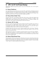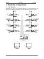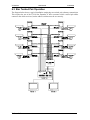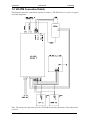
1
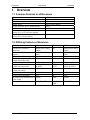
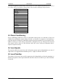
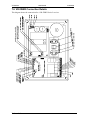
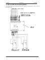
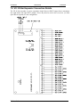
VR Series 2 User Manual 21/09/2005 Videoswitch VR Series 2 User Manual This manual covers the following products: VR-1PCB VR-1PM VR-1WBX Telemetry Receiver (PCB) Telemetry Receiver (Plug-in module) Telemetry Receiver (Weatherproof Box) VR-3PCB VR-3PM VR-3BX VR-3WBX Telemetry Receiver (PCB) Telemetry Receiver (Plug-in module) Telemetry Receiver (Indoor Enclosure) Telemetry Receiver (Weatherproof Box) VR-5WBX Telemetry Receiver (Weatherproof Box) VP-1 VP-1A Preset Module Preset Module with Alarms VX-18 Telemetry Star Expander This manual relates to Series 2 receivers fitted with software revision R2.0 onwards. Every effort has been made to ensure the accuracy of the information in this manual. However, Video Switch Ltd assumes no liability for losses incurred as a result of out of date information, errors or omissions. As part of a policy of continual product improvement, Video Switch Ltd reserves the right to make changes to product specifications and documentation without notice. No reproduction of this document or any portion of it is permitted without the specific written permission of Video Switch Ltd. © Video Switch Ltd 1997 Video Switch Ltd Unit 15 Redfields Industrial Park Church Crookham Hants GU52 ORD Videoswitch Tel: 01252-851510 Fax: 01252-851296 1 VR602c.doc VR Series 2 Videoswitch User Manual 2 21/09/2005 VR602c.doc VR Series 2 User Manual 21/09/2005 Contents 1. 1.1 1.2 2. 2.1 2.2 2.3 2.4 2.5 3. 3.1 3.2 3.3 3.4 3.5 4. 4.1 4.2 5. 5.1 5.2 5.3 5.4 6. 6.1 6.2 6.3 7. 7.1 7.2 7.3 7.4 7.5 7.6 7.7 7.8 8. OVERVIEW...............................................................................................................................4 Common Features to all Receivers ..............................................................................................4 Differing Features of Receivers...................................................................................................4 RECEIVER SETUP ..................................................................................................................5 Installation ...................................................................................................................................5 Self Test Sequence.......................................................................................................................5 Preset Conditioning .....................................................................................................................6 Lens Speeds .................................................................................................................................6 Lens Polarities .............................................................................................................................6 VR-1 AND VR-5 SETUP...........................................................................................................7 Twisted Pair Interface..................................................................................................................7 Twisted Pair Address...................................................................................................................7 Video Gain...................................................................................................................................7 Video Lift.....................................................................................................................................7 Pan, Tilt and Auxiliary Output Voltages .....................................................................................8 ADDITIONAL VR-5 SETUP ...................................................................................................9 Pan & Tilt Zero Offset Adjustment .............................................................................................9 Compensation Adjustment...........................................................................................................9 VP-1 & VP-1A PRESET SETUP ...........................................................................................10 Preset Positions..........................................................................................................................10 Preset Patrol Dwell Time...........................................................................................................10 Alarms (VP-1A only) ................................................................................................................10 Alarm Patrol Dwell Time ..........................................................................................................10 TELEMETRY CONFIGURATIONS....................................................................................11 Coax Operation..........................................................................................................................11 Daisy Chain Twisted Pair Operation .........................................................................................12 Star Twisted Pair Operation ......................................................................................................13 CONNECTION DETAILS .....................................................................................................14 VR-1PCB Connection Details ...................................................................................................14 VR-1PM Connection Details.....................................................................................................15 VR-1WBX Connection Details .................................................................................................16 VR-3PCB, VR-3BX, VR-3WBX Connection Details ..............................................................17 VR-3PM Connection Details.....................................................................................................18 VR-5WBX Connection Details .................................................................................................19 VP-1 and VP-1A Connection Details ........................................................................................20 VX-18 Star Expander Connection Details.................................................................................21 SAFETY WARNING ..............................................................................................................22 Videoswitch 3 VR602c.doc VR Series 2 User Manual 21/09/2005 1. Overview 1.1 Common Features to all Receivers Common Features Transmitter Compatibility Coax Telemetry Mains Power Zoom and Focus Drive (variable speed) Self Test Button Number of Presets Positions (using VP-1 or VP-1A Preset Option) Number of Alarm Inputs (using VP-1A Preset Option) All Receivers All VT and VXT Series 1 and 2 YES 240V (24Vac option) 6-12V YES 8 8 1.2 Differing Features of Receivers Differing Features Twisted pair Telemetry Input/Out Twisted Pair Telemetry Input Options Twisted Pair Addressing Switch Pan & Tilt Outputs (200W Maximum each) Variable Speed Pan & Tilt Latched Aux Functions (200W maximum each) Unlatched Aux Functions (200W maximum) Iris Drive (variable speed) Video Launch Amplifier Recommended maximum RG59 cable length Formats Videoswitch VR-1 20mA (Star or Daisy Chain) RS232, RS485 (Star) 240Vac NO 240Vac VR-5 20mA (Star or Daisy Chain) RS232, RS485 (Star) 16 positions 24Vdc NO AUX1, AUX2, AUX3 & AUX5 AUX4 NO AUX1 & AUX3 none YES AUX1, AUX2, AUX3 & AUX5 AUX4 6-12V YES 1000m NO NO 250m 6-12V YES 1000m PCB, PM, WBX PCB, PM, BX, WBX PCB, WBX 4 VR-3 NO NO VR602c.doc VR Series 2 2. User Manual 21/09/2005 Receiver Setup 2.1 Installation This section deals with setting up all VR-1, VR-3 and VR-5 receivers. For those operations which require commands from the transmitter, refer to the user manual for the transmitter (or keyboard) type being used. The receiver should be connected to the pan and tilt head and other equipment in accordance with the appropriate connection diagram in section 7. Where twisted pair links are shown, these could equally be fibre optic (microwave or IR) links via suitable data modems. Similarly, video data can be transmitted back to the transmitter via fibre optic (microwave or IR) links if twisted pair control is used. The red “OFFLINE” led on the receiver is normally on. When the receiver has been selected for control at the transmitter, and a telemetry key or joystick is being operated, the “OFFLINE” LED should go off. With VT type transmitters, if the continuous transmit mode is selected and the receiver is currently selected, the “OFFLINE” led will be off even if no telemetry command is being sent. With VXT type transmitters, the “OFFLINE” led of all connected receivers will go off for 2 seconds every 32 seconds if no telemetry commands are being sent (the VXT transmitters repeated update preset and other information in the receivers in case they have suffered from a power loss). 2.2 Self Test Sequence The self test feature allows the receiver to be tested in conjunction with the attached pan and tilt head, lens and auxiliary functions (such as wash/wipe and lamp). A small push button is provided on all receivers to start a self test sequence which momentarily activates each function in turn. The attached equipment should be observed to check that it is behaving as expected. If not, check the connections to the receiver. While the self test in progress, the green “TEST” LED will be turned on. The self test sequence will repeat until the button is pressed again. Videoswitch 5 VR602c.doc VR Series 2 User Manual 21/09/2005 The self test sequence is shown below. If the receiver is a VR-3 (which does not have iris, AUX 2,4 or 5), there will be a brief pause at these points in the test where nothing is being activated. Self Test Sequence Pan Left Pan Right Tilt Up Tilt Down Aux 5 Aux 3 Aux4 Aux 2 Aux 1 Zoom In Zoom Out Focus In Focus Out Iris In Iris Out 2.3 Preset Conditioning Preset conditioning enables the receiver to determine which presets are connected (if any) and whether the potentiometer output voltage increases or decreases in response to movement in a particular direction. Initiate the conditioning sequence from the transmitter if a preset option PCB is added or removed, or if the wiring to the presets is changed in any way. The pan, tilt, zoom and focus motors will be driven in each direction while the receiver learns the information that it requires to operate correctly. 2.4 Lens Speeds The speed at which the zoom, focus and iris functions operate may be independently set to one of eight values. It is suggested that maximum speed (i.e. eight) is selected to start with. 2.5 Lens Polarities The polarity of the zoom, focus and iris outputs may be independently set from the transmitter so that the lens operates in the required direction when the zoom, focus and iris up or down functions are pressed. Videoswitch 6 VR602c.doc VR Series 2 User Manual 21/09/2005 3. VR-1 and VR-5 Setup These are the additional setup details specific to VR-1 and VR-5 receivers. 3.1 Twisted Pair Interface The receivers are normally supplied with a 20mA current loop interface, but may be supplied with RS232 or RS485. Ensure that the receiver interface has the same type of interface as the equipment to which it is connected (i.e. transmitter, star expander, fibre-optic/infra-red/microwave modem). 3.2 Twisted Pair Address The address switch on each receiver using twisted pair telemetry must be set to correspond with the camera number as shown in the table below. This applies to daisy chain, star and mixed configurations. Camera Number (Transmitter input number) 1 2 3 4 5 6 7 8 9 10 11 12 13 14 15 16 Address Switch Setting 0 1 2 3 4 5 6 7 8 9 A B C D E F 3.3 Video Gain The video gain of the receiver is set from the transmitter. Normally a minimum gain of 1 will be appropriate for short cables, going up to a gain of 8 for maximum length cables. Note that the gain steps will not appear equal as every other step provides an alternative cable compensation setting. Choose whichever setting gives optimum picture clarity. 3.4 Video Lift The video high frequency lift of the receiver is set from the transmitter. The lift ramps up or down over a period of time (up to 30 seconds) while the up or down commands are transmitted. Start of with minimum lift. Increase the lift to achieve optimum picture sharpness whilst avoiding excess lift which result in over exaggeration of vertical edges. Videoswitch 7 VR602c.doc VR Series 2 User Manual 21/09/2005 3.5 Pan, Tilt and Auxiliary Output Voltages The VR-1 receiver has a connector which enables the pan & tilt and auxiliary functions to operate at a different voltage to that of the mains. 3.5.1 Output Voltage Same as Supply Voltage For operating the pan, tilt and auxiliary functions at the supply voltage (normal configuration) connect two link wires to the receiver as follows: 3.5.2 Output Voltage Different to Supply Voltage If a different output voltage is required (e.g. 240Vac supply, 24Vac pan & tilt) then a suitable transformer is required. Typically a 60VA torroidal transformer with a 240V primary and a 24V secondary is used. Connect the receiver to the transformer as follows: Videoswitch 8 VR602c.doc VR Series 2 User Manual 21/09/2005 4. Additional VR-5 Setup These are the additional setup details specific to VR-5 receivers. 4.1 Pan & Tilt Zero Offset Adjustment The VR-5 receiver has two preset potentiometers for setting the pan and tilt output voltages to zero when no movement is required. These potentiometers are factory set and do not normally need altering. If adjustment is required: Connect a DC voltmeter across the “+” and “-” PAN output terminals and adjust the pan ZERO potentiometer to obtain zero output voltage. Connect a DC voltmeter across the “+” and “-” TILT output terminals and adjust the tilt ZERO potentiometer to obtain zero output voltage. 4.2 Compensation Adjustment The VR-5 receiver has two preset potentiometers (identified as “COMP”) to set the pan and tilt motor current compensation. These potentiometers should normally be set fully anti-clockwise. For heavy duty pan and tilt heads (i.e. not domes), they may be turned clockwise in order to improve the low speed characteristics of the receiver. Make sure that no speed instability is introduced by turning them too far. If the compensation potentiometers are adjusted, it may be necessary to adjust the zero offsets again. Videoswitch 9 VR602c.doc VR Series 2 User Manual 21/09/2005 5. VP-1 & VP-1A Preset Setup These are the additional setup details specific to any receiver fitted with a VP-1 or VP-1A preset option PCB. 5.1 Preset Positions Up to eight different presets positions may be stored. This is performed by positioning the pan and tilt and lens functions at the required location and then sending a set preset command from the transmitter. The process is repeated for each preset position. It is suggested that if all eight are not required, the unused ones are set anyway (possibly to duplicate positions). 5.2 Preset Patrol Dwell Time The preset dwell time is the period for which the receiver waits at each preset position when multiple presets are selected. The dwell time is set from the transmitter by sending a start command, then a stop command after the required dwell interval (1 second to 4 minutes). The alarm enable “AUX2” must be off when the preset dwell time is being set. 5.3 Alarms (VP-1A only) The VP-1A provides eight alarm inputs. These should be connected to normally open contacts on the alarm device (e.g. PIR detector). When an alarm occurs, if AUX2 is currently on, the corresponding preset number will be selected. Alarms take priority over presets, but may be overridden by manual control. If AUX2 if off, alarms will be ignored. If multiple alarms exist on the same receiver, each preset position will be visited in turn. Thereafter, the receiver will cycle between all alarms which are still present, pausing at each one for the duration of the preset dwell time. Alarm output relay contacts are provided for connection from the receiver back to the transmitter. This enables the transmitter to select the appropriate camera for display on a monitor when an alarm occurs. If multiple alarms exist on different receivers, the transmitter will cycle between them if set to AUTO sequence mode. 5.4 Alarm Patrol Dwell Time The alarm patrol dwell time is the period for which the receiver waits at each alarm position when multiple alarms are present. The dwell time is set from the transmitter by sending a start command, then a stop command after the required dwell interval (1 second to 4 minutes). The alarm enable “AUX2” must be on when the alarm dwell time is being set. Videoswitch 10 VR602c.doc VR Series 2 User Manual 21/09/2005 6. Telemetry Configurations 6.1 Coax Operation The diagram below shows a typical installation employing coax telemetry transmission. The telemetry control information is transmitted via the same coax cables that are used for the video. Videoswitch 11 VR602c.doc VR Series 2 User Manual 21/09/2005 6.2 Daisy Chain Twisted Pair Operation The diagram below shows a typical installation employing daisy-chained twisted pair telemetry transmission. Note that, unlike for the Series 1 receivers, it does not matter in which order the twisted pair cables go to the receivers. The address switches must however be set correctly. Videoswitch 12 VR602c.doc VR Series 2 User Manual 21/09/2005 6.3 Star Twisted Pair Operation The diagram below shows a typical installation employing star twisted pair telemetry transmission. This requires the use of the VX-18 Star Expander. It does not matter which twisted pair cables connect to the which receivers, but the address switches must be set correctly. Videoswitch 13 VR602c.doc VR Series 2 User Manual 21/09/2005 7. Connection Details 7.1 VR-1PCB Connection Details This diagram shows the connections for a VR-1PCB Series 2 receiver. Videoswitch 14 VR602c.doc VR Series 2 User Manual 21/09/2005 7.2 VR-1PM Connection Details This diagram shows the connections for a VR-1PM Series 2 receiver. Note: The wiring is not the same as for the VR-1PCB because the polarisation of the connectors is reversed. Videoswitch 15 VR602c.doc VR Series 2 User Manual 21/09/2005 7.3 VR-1WBX Connection Details This diagram shows the connections for a VR-1PM Series 2 receiver. Videoswitch 16 VR602c.doc VR Series 2 User Manual 21/09/2005 7.4 VR-3PCB, VR-3BX, VR-3WBX Connection Details This diagram shows the connections required to be made to a VR-3 Series 2 receiver to typical associated equipment: Videoswitch 17 VR602c.doc VR Series 2 User Manual 21/09/2005 7.5 VR-3PM Connection Details This diagram shows the connections required to connect a VR-3PM Series 2 receiver to typical associated equipment. Note: The wiring is not the same as for the VR-3PCB because the polarisation of the connectors is reversed. Videoswitch 18 VR602c.doc VR Series 2 User Manual 21/09/2005 7.6 VR-5WBX Connection Details This diagram shows the connections for a VR-5WBX Series 2 receiver. Videoswitch 19 VR602c.doc VR Series 2 User Manual 21/09/2005 7.7 VP-1 and VP-1A Connection Details This diagram illustrates the connections required to implement all functions of a VP1 or VP-1A preset option PCB. Videoswitch 20 VR602c.doc VR Series 2 User Manual 21/09/2005 7.8 VX-18 Star Expander Connection Details The VX-18 Star expander is used to expand the single 20mA or RS232 output from a transmitter into eight 20mA and eight RS232 outputs. These may then be used to drive receivers (via fibre optic links if required) in a star configuration. Videoswitch 21 VR602c.doc VR Series 2 User Manual 21/09/2005 8. Safety Warning Check carefully that the live, neutral and earth supply leads are connected to the correct terminals as detailed in this manual. Note that there are differences between receiver types and between Series 1 and Series 2 receivers. This manual covers only Series 2 receivers and these are identified as such on their PCB. Before connecting the mains supply to the unit, check that the supply voltage corresponds with the voltage indicated on the power rating label on the unit. To avoid the risk of electric shock, the mains supply must be disconnected from the unit before the cover is removed. This equipment must be earthed. The unit is protected with an internally mounted mains fuse. For continued protection against the risk of fire, replace only with the same type and rating of fuse. Videoswitch 22 VR602c.doc