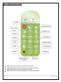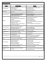
1
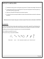
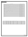
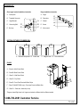
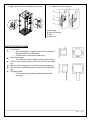
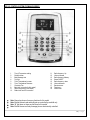
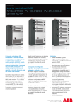
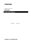
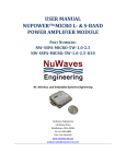
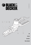
CONTEMPORARY STEAM ROOM Installation & Operation Manual Note: You must read all installation & operation instructions prior to assembly and use of this unit. 1|Page Rev 10/2012 Table of Contents Notice to Installers Packing List Product Features Chart Packing List Rough-In Diagram Water & Electric Requirements Installation Instructions Faucet Functions & Usage Cleaning, Maintenance & Tips BF1101 Main Control Panel Diagram Description of Functions MID1101 Remote Control Troubleshooting ………………………………………….. ………………………………………….. ………………………………………….. ………………………………………….. ………………………………………….. ………………………………………….. ………………………………………….. ………………………………………….. ………………………………………….. …………………………………………. ………………………………………….. ………………………………………….. ………………………………………….. 3 3 4 5 6 7 8-11 11 12 13 14 15 16 Thank you for selecting Steam Planet Corp Computerized Steam Rooms. In order to operate and use the product properly, please follow all instructions provided in this User’s Manual. Our company reserves the right to change the Manual at anytime. The manual takes effect the date it is published. This manual shall prevail if there is any difference between this and previous documents and manuals. 2|Page Rev 10/2012 NOTICE TO INSTALLERS 1) The distance from the ground to the ceiling has to be minimum of 3.9” higher than the height of the steam room. 2) The water pressure has to be more than 3kg/cm2 (47-72 psi) and, if the pressure is lower than required, you may install a booster to the water supply. 3) Please use a 20-amp 220V GFI breaker for the electrical connection. 4) We advised to have an access panel installed on the side of the electrical/water connections for maintenance and service. Manufacturer reserves the right to change specs or features at anytime. Please check to confirm details. 1-866-783-2661 PACKING NOTE: (1) When first opening the boxes, please make sure everything is in good condition, especially if any visible damage has been done to the package, please contact Steam Planet immediately with photographic documentation of the damage. (2) Make sure all water and electrical components are up to local and national standards. (3)Two installers are required for these units. (4) Here are the tools you may need for installation: Rubber mallet wrench level tape measure screwdriver pencil 4mm allen wrench 3|Page Rev 10/2012 PRODUCT FEATURES DESCRIPTION 3kW Quick heating Self-Draining Steam Generator w/Steam Aromatherapy Cup Multiple Body Massage Jets Hand-held Shower w/ Various water massage settings & adjustable height bracket 8 inch wide water-drenching Rainfall Shower Thermostatic / Anti-scald Faucet “Special Process” Black Tempered Glass walls and front Clear Glass Unique “Glass Touch” Control Panel FM Radio Wireless transmitter (optional extra) transmits from any electronic device Hand held Remote control for entire panel control “Chroma-therapy” LED multiple Color Lighting Waterproof Oak Shower Grid Removable Bench Circulation Fan Accessory Rack Phone Hinged door Stone composite base included Assembles from inside the unit Left / Right Models Available Model MA6020 MA6023 MA6027 MA6028 Voltage 220V 220V 220V 220V Power 3kW 3kW 3kW 3kW Frequency 50-60Hz 50-60Hz 50-60Hz 50-60Hz Length 1090mm / 43 Inch 900mm / 35.4 Inch 1500mm / 59 Inch 1500mm / 59 Inch MA6020 Width 800mm / 31.5 Inch 900mm / 35.4 Inch 813mm / 32 Inch 1016mm / 40 Inch MA6023 Height 2184mm / 86 Inch 2184mm / 86 Inch 2184mm / 86 Inch 2184mm / 86 Inch 4|Page Rev 10/2012 PACKING LIST Glass angle bracket installation instruction Hinge installation instruction A.Glass panel A.Hinge B.Threaded Connector B.Glass door A C.Angle Bracket D.Connecting Bolt E.Bolt cap E D C B C.Gasket B D.Screw C D E A E.Allen wrench SECTION PICTURE OF RUBBER SEAL A B A.Half-moon shape seal B.Corner seal C D C.Magnetic seal D.Door bottom seal GLASS A:Glass A—Main Panel, Black B:Glass B—Back Panel, Black C:Glass C—Side Panel, Black D B A C E G D:Glass D—Top, Black E:Glass E—Front Clear Panel with Black Stripe F:Glass F (M-A6027/6028 only)—Front clear Panel with Black Strip G:Glass G— Clear door, black strip on top. F *Diagram shows Right-hand unit, hinges are located on different side for different models. 1-866-783-2661 Customer Service 5|Page Rev 10/2012 ROUGH-IN DIAGRAMS Note: All diagrams below are for right hand units only. Please reverse for left hand units. M-A6020 (43×31.5×84in.) M-A6028 (59×40×84in.) A. Cold water in B. Power jack(AC30A) C. Hot water in M-A6023 (35.4×35.4×84in.) M-A6027 (59×32×84in.) Rated voltage Rated power Rated frequency AC220V 50/60Hz 3KW 6|Page Rev 10/2012 WATER AND ELECTRICITY INSTALLATION INSTRUCTION FOR ALL MODELS (1) Water: Two water lines for cold and hot water respectively ½-inch National Pipe Thread (NPT). (2) Power: Power requirement: Single-phase three-wire 220V power supply. TECHNICAL INFORMATION Materials: Tempered Glass Power Supply: 3KW 20amp, 220V Steam Ready: 2-5 MIN ELECTRICAL INFORMATION 1 dedicated 12-2 line for steam (line 1, line 2, and ground) Single-phase three-wire 220 volt, 20 amp GFCI breaker The length of the wire for the machine is 1.5m (adjustable); it can be changed to a suitable length. Connect the overhead light, speaker, fan, CD, telephone according to the tags on the wires. Do not connect the wire “O3” to anything. Connect main power supply. PLUMBING INFORMATION The unit is equipped with 3 ft. hot and cold, metal braided water supply hose with ½-inch national pipe thread to connect from faucet/manifold (Manifold is located. 4 ft. high on rear of unit) to the shutoff valves (should be installed where they can be accessed). Note: base edge sets directly against back and sidewall. Do not install any pipes along walls as to impede the base from setting flush against them.. Install hot and cold shutoffs with ½ -inch male national pipe thread (not included). Install shutoffs where they can be accessible. Access panel near controls, pumps, and jets is recommended Drainage: It is advised to have base onsite before preparing drain location. The diameter of the drain hole should be larger or equal to Φ40mm (1.6 inches). Note: The flexible drain hose included with this unit is for installation into a floor drain only. Substituting the existing drain setup for a setup of the installers’ choice will not void the warranty of the unit as long as there is no evidence of misuse or damage to the base.. All fixtures and fittings must be checked for tightness as they may have been loosened during transport GENERAL INFORMATION Connect hot and cold supplies and make all electrical connections just before unit is set into place. Units come broken down in panels and are assembled with screws, nuts and bolts on site. This unit assembles from the inside for convenience. Note: All shower bases are a man made stone composite and may need to be set in mortar for leveling purposes. It is advised to have base onsite before preparing drain location Access panel area recommended Manufacturer reserves the right to change specs or features at anytime. Please check to confirm details. 1-866-783-2661 Caulk all needed seams and joints with 100% silicone caulk. DRAIN INSTALLATION FOR ALL MODELS For glass steam room and shower room with 150mm shower tray: A: Glass A B: Steam Generator Drain C: Shower Drain D: Shower tray 7|Page Rev 10/2012 INSTALLATION INSTRUCTIONS FOR MA6020 & MA6023 Note: Silicone joints & seams where needed Note: Determine the drain setup. There needs to be a 3/8 inch diameter hose connected from the steam box to the main drain. 1. Place shower tray in the corner where it will be permanently located. Note: The handing (R/L) of your unit determines which side the mounting plate goes (ie: A right handed unit has the mounting plate on the right side) 2. Make sure the installation holes for the electric parts and the steam generator are lined up with installation holes; connect it with M6X25 Hex bolts. 4. Install angle brackets over the installation holes of glass A, connect with connector bolts (make the connection snug, but loose enough to make adjustments.) Connector bolt caps will be installed when final tightening is complete. Connect water supply lines and electrical lines. 5. Place bottom edge of glass A into the slot on the base as shown. A small amount of soap or lubricant on the gaskets will help with installation. Helpful hint: install the shelf brackets to back panel before positioning in base. See section 3.19 for more info. 3. Insert the half-moon shaped rubber seals (shown in picture below) onto the left, right and top edge of glass A. 8|Page 6. The wires for the fan, speaker, and light are labeled. Make the corresponding connections from the accessory to the wire coming from the control box. *Note: Be cautious when making this connection. The pins of the connector can easily bend if connected improperly! A: Wire for control panel B: Temperature Sensor C: Wire for speaker/fan/light D: Speaker E: Fan F: Lights G: Connecting terminal for light/fan/speaker H: Control panel connecting terminal 7. Install the angle bracket to the holes on glass B (black back panel). Connect with screw. Tighten snugly, but leave enough tension to adjust. Insert the corner seal on the on the left side of glass B. Note: Attach glass shelf brackets to back of panel before proceeding. 8. (MA6020, MA6027& MA6028) NOTE: Attach glass shelf brackets to the holes in glass B. 10. Insert the corner seal to the right edge of glass C, then install angle brackets to the glass panel (C). Tighten snugly, but leave enough tension to adjust. Refer to picture below. Install glass shelf brackets on panel C before moving forward 11. Place glass C into the slot onto the base and insert into the corner seal of glass B. Note: Glass B is the black panel, and glass C is a black panel. Line up the installation holes and connect glass B and glass C. 12. Assemble the half-moon shaped seals on the sides a, b, and c of glass D (top). See illustration below. Attach angle brackets to glass panel D. 9. Place the bottom edge of glass B into the slot on the base as shown below. Align the holes and connect with angle brackets. Connect to glass A. B C A 9|Page 13. Place glass D (top) on the top of the unit, align connecting holes with glass D to glass panels A, B, and C. Use M6X10 connector bolt to connect. Please refer to illustration below 14. Connect the rainfall showerhead water line to faucet, screw in. Also, connect the light, fan and radio. Then locate the middle water pipe, which is under the faucet, and connect it to the steam box water inlet. Secondly, connect the black steam line, which is on the side of the steam box, to the steam outlet. Connect steam box drain line to the steam outlet drain. Finally, connect the cold and hot water lines to the water manifold, the red one is for hot water, while the blue is for cold. A: Steam outlet B: Main Control box C: Black steam hose (insulated) D: Diverter E: Rainfall shower head supply F: Hose clamps G: M4×25 screw H: Hose clamp At this point, you should have all electric & water features connected! 16. (MA6027 & MA6028 ONLY) Attach glass panel E which has a black stripe across the top and side to glass panel D and A. 17. (M-A6027 & M-A6028 ONLY) Insert the corner seal and corner brackets on the left side of glass F (will have holes for door hinge) attach to panel D & C with angle brackets and connector bolts. Attach door hinges and door Panel G. 18. Put the wood floor grids in the shower tray and benches in the unit. Attach flexible waterline to outlet on panel A and the other end to the handheld shower wand. Attach to the bracket. Note: the hex nut of the water line goes on the panel outlet. 15. (M-A6020 & M-A6023 ONLY) Align glass E in slot of base, align the installation holes of glass E to the holes of Glass D and Glass A. Glass E has a black stripe long the top and side. Use the Angle Bracket & Connector Bolt; apply connector bolt caps after final adjustments. Attach the Door Panel G that has a black stripe along the top. 10 | P a g e 19. Attach handle to the door and shelves to panels B and C. 20. Steam Cup Connection Diagram D C B A A: Steam outlet B: Steam line Connector C: Glass D: Steam hose FAUCET FUNCTION AND USAGE On/Off Control o When the temperature is adjusted, the water flow can be adjusted through the handle in the middle section o Clockwise turns on, and counterclockwise turn off Water Diverter handle o Turn the diverter handle according to the signs marked on its face. When you use the hand held shower, turn the knob to the hand held shower sign; When you use the massage jets, turn the knob to the back massage sign. When you use the rainfall shower head, turn the knob to the rainfall shower sign Cold Water and Hot: o Turn the faucet to left and right to increase/decrease the water temperature. 11 | P a g e CLEANING AND MAINTENANCE 1. Liquid detergents and soft cloth should be used. DO NOT clean with acetone and ammonia detergents on fixtures. Do not use detergents with formic acid or formaldehyde. Do not use any abrasive cleaners. 2. Mineral deposits/scaling on surface can be cleaned by soft cloth with heated vinegar. 3. After every 30 uses, we suggest you to clean the steam generator. 4. Make a solution mixed with 1.5-1.7 liter of warm water and 5-10 grams of citric acid. Or, use straight white vinegar. Pour the solution into the steam generator through the cleaning valve on the inside of the shower. Turn it on after 8 to 10 hours; wait for it to be discharged as steam. General 1. User’s electric must meet national safety standard for voltage and frequency. Power supply shall be consistent with the parameters marked on the product. 2. The ground should always be connected to the system. 3. We advise to use a water filtration system for the steam generator unit. One Recommended filtration system is Whirlpool WHKF-DWHV. 12 | P a g e BF1101 CONTROL SYSTEM FOR MA602X SERIES 1. 2. 3. 4. 5. 6. 7. 8. 9. 10. Time & Temperature setting Rainfall shower Body Massage Jets Top light Time / Temperature Increase Time / Temperature Decrease Circulation Fan Back light (not active for this model) Sauna (not active for this model) Radio on/off and CD connection 11. 12. 13. 14. 15. 16. 17. 18. 19. Radio frequency -Up Volume Increase Radio frequency Memory Steam ON/OFF Radio frequency -down Volume decrease Remote sensor Telephone Power on/off Note: Sauna key does not have any functions for this model Note: Rainfall shower head and body jets are controlled by manifold only Note: “B” light does not have any functions for this model Note: Rainfall shower and body massage jets are electronically controlled. 13 | P a g e DESCRIPTION OF FUNCTIONS Not in the same order above 1. ON/OFF Key Under ON state, press “ON/OFF” Key on the panel to start the system, and the top light is turned on, all functions are activated on the panel, the back light is on, LCD shows the ambient temperature and all icons are lit; press the “ON/OFF” to shut off the system. Press other keys except “ON/OFF” key under standby and OFF state, the backlight will come on, if the systems is not turned on, the backlight will be turned off in 30 seconds. Following functions are available when the system is on: 2. Circulation Fan: Press key on the panel to start the fan the icon will light up on the LCD screen. Pressing the fan key again, will shut down the circulation fan. This function circulates the steam throughout the enclosed shower space. No special exhaust needed for this function. 3. Steam Temperature and Time Setting: Press TIME & TEMPERATURE key on the panel so that temperature icon is on the screen, system will enter into steam temperature setting state. Press “+” or “-“key to increase or decrease temperature. The temperature range is 25-60°C (77140°F); press this key again to enter into time setting state. The time range is 1-99 minutes. If time or temperature is not adjusted within 5 seconds, the system will automatically recover to display room temperature. 4. Steam: Press key on the panel. The default steam time is 45 minutes, and the highest temperature is 45°C (113°F). By pressing the steam key again, the steam system will shut off. 5. CD/FM Function: Press key on the control panel or remote to activate the FM Radio, the corresponding icon will light up on the control panel. The system will automatically switch to the previous frequency. Pressing this key the second time, will switch the function to CD mode. The display will show the corresponding icon. Pressing the again will shut off the system. 6. Volume Adjustment: When the speaker is ON, pressing the “+” or “-“on the key panel to increase or decrease the volume. When changing the volume, the LCD monitor will display the corresponding changes. 7. Frequency or Channel Adjustment: When the radio is ON, press the “TUN” key to adjust the frequency (radio channels). Pressing the “+” or “-“ button once, will increase or decrease the frequency by 0.1MHz, holding it for 1 minute will automatically search channels. The search will stop once the next station is found, and the LCD panel will display the corresponding channel. When the system displays channel, press “+” or “-“key to adjust channels, the range is 1-25 channels. 8. MEM, HZ, CH Selection Key: When radio in ON, press “MEM” key to select radio frequency (H) or channel (CH). Hold this key to store the correct frequency into channel, LCD display will show “MEM” when stored. 9. Telephone Function (Operational only when is plugged in or available): When there is an incoming call, telephone will ring, system will automatically shut off the radio/CD. Press key on the panel to stop the ring and receive the phone call. LCD display will show the telephone icon; also, the shower functions will automatically shut off. Press phone key again to end the call. (You cannot dial out) 10. Mood Light: Top light will turn on when the system is activated. Press the Light key on the panel or remote control to turn on or turn off the mood light. 14 | P a g e MID-1101 REMOTE CONTROL SYSTEM Note: Sauna key does not have any functions for this model Note: Rainfall shower head and body jets are controlled by manifold only Note: “B” light does not have any functions for this model Note: Rainfall shower and body massage jets are electronically controlled. 15 | P a g e TROUBLESHOOTING Problem Unit does not start Switch failure Automatic shutdown No steam Automatic Protection No sauna Temperature is too high Steam is Shutting off Water from steam outlet Audio not working Possible Reason Solution 1. Power line is not connected properly. 2. Insufficient power supply. 3. Fuse is damaged 4. Current circuit breaker is damaged. 1. Current circuit breaker tripped or damaged 2. Short circuit 1. The intake valve or drain valve is damaged 2. The drain for the drain valve is jammed. 1. Electric components were damaged. 2. Electrical circuit is worn out. 1. No water supply 2. Water pressure is too low 3. The heating element of the steam generator is damaged 4. No water in steam generator 5. Steam pipe is jammed or broken 6. Heating time is not set 7. Temperature in the unit is higher than the set steam temperature setting 1. Water pressure is too high 2. Intake valve or drain valve is jammed 3. Drain pipes and drain is jammed 4. Steam pipes are jammed 1. Heating element is damaged 2. Circuit board or the component is damaged 1. Preset temperature is too high 2. Temperature sensor is damaged 1. reconnect the power supply 2. Power supply must reach 50/60Hz – 220V 3. Replace the 2A fuse 4. Replace the circuit breaker. 1. Replace the circuit breaker or reset. 2. Recheck the circuit. 1. Replace the intake valve or drain valve. 2. Clear out the drain pipe. 1. Repair or replace the corresponding components. 2. Replace circuit breaker. 1. Preset time ran out 2. Preset temperature is too low 3. Heating element is damaged 1. Reset the time 2. Increase the temperature on keypad/remote 3. Repair or replace the heating element 1. The water level sensor is damaged 2. The water level circuit is not working 1. No signal 2. Volume not high enough 3. Speaker is damaged 4. Antenna is loose/no signal 5. Circuit board is damaged 6. Circuit is loose, or there is no contact 1. Check the sensor 2. Check the water level circuit 1. Readjust for FM signal 2. Increase the volume 3. Replace the speaker 4. Connect the antenna and adjust the direction 5. Replace circuit board 6. Re-plug the circuit component or replace Check the control cable, release and re-plug. Note: align arrows and plug tightly Check the water level control cable between steam generator and the electrical box. Release the screw and re-plug in the head. Screen problem Problem with the control cable Water & Drain Valve problem Water level control cable is not properly connected 1. Wait for the water supply to start 2. Install Pressure pump 3. Replace heating element 4. Check the water intake valve. 5. Clean out the jammed materials or replace the pipe. 6. Set Steam timer 7. Raise the temperature on the keypad/ remote 1. Lower water pressure 2. Clear out jamming material in intake and drain valves 3. Clean out the drain pipe 4. Clear out the steam pipes 1. Replace the heating element 2. Replace circuit board 1. Adjust the temperature lower 2. Replace the sensor 16 | P a g e 17 | P a g e 18 | P a g e