1
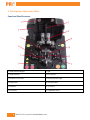
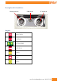
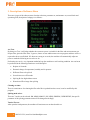
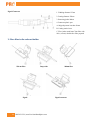
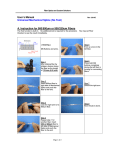
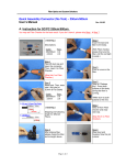
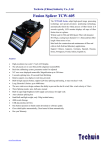
PRO-790
Fusion Splicer
Operation Guide
PRO-790
Table of Contents
1. Introductions .........................................................................................................................................................3
2. Description of Operation Units ...........................................................................................................................4
Panel and Wind Protector .......................................................................................................................................4
Description of side outlet box.................................................................................................................................5
Kaypad....................................................................................................................................................................5
3. Description of Software Menu .............................................................................................................................6
4. Switch on, switch off and stand by ....................................................................................................................10
5. Basic procedure of splicing ................................................................................................................................10
1. Prepare fiber .....................................................................................................................................................10
2. Place fiber in the relevant holder ......................................................................................................................12
3. Fiber cutting .....................................................................................................................................................13
4. Place fiber .........................................................................................................................................................13
5. Heating operation .............................................................................................................................................13
6. Charging of Machine..........................................................................................................................................13
7. Standard package and optional .........................................................................................................................13
9. Safety operation Norms .....................................................................................................................................13
10. Warnings and cautions for transportation.....................................................................................................14
11. Periodical replacement of component.............................................................................................................14
2
888-545-1254 | www.PrecisionRatedOptics.com
PRO-790
1. Introductions
It is a light weight, small and fast FTTH Fusion Splicer, which is designed to splice bare fiber, pigtail, patch cord,
Optical fiber drop cable and make of SC,FC, LC connector on the spot by changing different fiber holders
equipped. It is an ideal tool for the splicing of fiber network terminal, which is able to work in narrow and small
room.
Specifications
Applicable Fibers
SM, MM, DS, NZ-DS (G655), G655, G657
Fiber Diameter
Cladding Diameter: 80 -150μm; Coating Diameter: 100~1,000μm
Average Splice Loss
0.01db (MM), 0.02db (SM), 0.05db (DS/NZDS/G.655/G.657)
Return Loss
60dB
Tension Test
2.0N (Standard)
Splice Time
8 Seconds
Sleeve Lengths
25mm, 40mm, 50mm
Sleeve Heating Time
35 Sec.
Splicing Programs
Manual and Automatic Settings
Alignment
PAS Technology
Fiber Holder (Bare Fiber)
250μm ~ 900μm, Pigtails, Patch Cords or Optical Fiber Drop Cables
Monitor
3.5” Color LCD
Interface
USB
Languages
English, Spanish, Chinese
Data Storage
10,000 Splice Results
Electrode Lifespan
5,000 Splicing Operations
Operating Temperature
-0.4º F ~ 122º F (-18º C ~ 50º C)
Storage Temperature
-40º F ~ 176º F (-40º C ~ 80º C)
Power Supply
Internal Li-Ion Battery, AC/DC Adaptor (12v) Battery Capacity: Approximately 120 Splices
and Oven Uses
Environmental Conditions
0 ~ 95% (Humidity), 0 ~ 5000m (Altitude), 15mph (Max. Wind Velocity)
Weight & Dimensions (LxWxH)
4.7” x 4.7” x 4.5” / 3.75 lb (120 x 120 x 115 mm / 1.7 kg)
Warranty
Standard 1-Year Manufacturer Warranty (Extended Warranty Available)
www.PrecisionRatedOptics.com | 888-545-1254
3
PRO-790
2. Description of Operation Units
Panel and Wind Protector
1: Wind Protector Magnet
7: light
2: Wind Protector
8: Fiber Presser
3: Electrode Cover Plate
9: Heating indicator light
4: Holder Base
10: Electrode Base
5: Electrode
11: V-Groove
6: Key Board
12: Alignment wheel
4
888-545-1254 | www.PrecisionRatedOptics.com
PRO-790
Description of side outlet box
Charging input port
USB interface
DC output port
Kaypad
Menu/Confirm
Exit/Return
Up Down/Modify
Splice/Re-arc
Heating
Reset
Switch
www.PrecisionRatedOptics.com | 888-545-1254
5
PRO-790
3. Description of Software Menu
There are 6 pages of the software menu: function selection, parameter set, maintenance set, record check and
operation guide, description of subpage is as follows:
Arc Test:
By doing Arc Test, it will judge whether the current arc power is suitable for the fiber and environment or not.
Prepare fiber, place the fiber in the V-groove, choose arc test and then enter arc test program, and there will be a
report after the arc test finished. If it shows arc strong or arc weak, the machine will automatically adjust arc
power to make the following arc test to be arc ok.
Performing Arc test is a very important method to keep the machine at a well working condition. Arc test has to
be performed in the following situations to avoid bad splice:
•
Replace of electrode
•
Dramatic change of temperature, humidity and air pressure
•
Different fibers to be spliced
•
Several times use of Electrode
•
Splicing db loss high without reason
•
Distortion of fiber image after splicing
Cleaning arc time:
There is a transient arc for cleaning the fiber after fiber is pushed into the screen, it can be modified by this
program.
Splicing mode select:
There are 7 modes can be selected: SM, MM50, MM62.5, DS, NZDS, ERBIUM, USER DEFINE, the specific
parameter of the splicing parameter menu will be changed accordingly.
Tension Test set:
After open the wind protector, the machine will tension test or not based on this set.
6
888-545-1254 | www.PrecisionRatedOptics.com
PRO-790
Heating time:
Heater will heat according to the time set after pressing the heat button. Pressing heating button during heating
operation, it will stop heat.
Auto start set:
If this item is OPEN, after close the cover in stand by status, the machine will start splice automatically.
Parameter Set II
Arc power:
This parameter has the function over cleaning arc, pre arc, splicing arc, arc again, it can be set from 10-100.
Pre arc time:
It is time between the start of arcing and start of forward.
Arc time:
It is the continuous arc time after forward.
Overlap length:
The forward length during arc process.
Arc again:
After splicing, pressing arc button, the machine will arc again.
Angle threshold:
During splicing process, if the fiber angle is greater than this parameter, PAUSE II will be automatically started
(Even if PAUSE II is in off condition). Note: Changing arc power and arc time has an effect on arc test result.
Parameter Set III
www.PrecisionRatedOptics.com | 888-545-1254
7
PRO-790
Push speed:
It decides motor speed and reset speed.
Alignment gap:
The distance between the end face of left and right fiber after aligned.
Gap position:
The position of end face after fiber aligned, it is set in the mid of the screen usually. When the arc position is not
in the mid of the screen (can be verified by the result of arc test), this parameter can be modified to make the gap
position and arc position stay in same.
Alignment offset:
If the alignment offset is greater than this parameter, PAUSE II will be automatically started (Even if PAUSE II is
in off position).
PAUSE I:
If this item is open, during the process of splicing and arc test, the fiber will stop after pushed into screen.
PAUSE II:
If this item is open, during the process of splicing and arc test, the fiber will stop after alignment.
Maintenance Set:
Lens check:
Check whether there is dust or saturation points in lens, by this check result, it can judge if the optical system of
this machine suitable for splicing operation or not.
Motor resetting position:
The distance that motor left the initial position after switch on or resetting.
Day setup:
Set year, month and day.
Clock setup:
Set hour, minute and second.
Parameter resume:
Resume all parameters to default value.
8
888-545-1254 | www.PrecisionRatedOptics.com
PRO-790
Language:
Chinese or English.
Records check:
Arc times:
Arc times of electrode, including arc test, splicing arc, splicing again and manual splicing.
Arc times clear:
Recommend to do this operation after changing of electrode.
Heat times:
Working time of heater.
Heat times clear:
Recommend to do this operation after changing of heater.
Records view:
View the operation record of this machine, including splicing time and splicing result. If the splicing loss is 2.55,
that means splicing failed.
Records clear:
Clear all splicing records, maximum records are 10000 (0000-9999).
Operation guide:
It is a simple operation guide, read by pressing page-turning key.
www.PrecisionRatedOptics.com | 888-545-1254
9
PRO-790
4. Switch on, switch off and stand by
Pressing switch will power on the machine
In standby, pressing switch continuously, machine will buzz, when buzzing stopped, still pressing the switch
button, the machine will power off once loosing the switch button.
Stand by:
Stand by after power on, and it will show the current day, time and battery capacity and available operation
button.
5. Basic procedure of splicing
1. Prepare fiber
250um fiber
Strip fiber coating by small slot of CFS-2 stripper, stripped length A is more than 18mm, see following Fig.
1. Cladding diameter 125um
2. Coating diameter 250um
A. Stripped part not less than 18mm
10
888-545-1254 | www.PrecisionRatedOptics.com
PRO-790
900um Fiber
Strip protecting jacket of pigtail by big slot of CFS-2 stripper, length A more than 20mm; Strip cladding of pigtail
by small slot of CFS-2 Stripper, retain length B less than1 mm, see following Fig.
1. Cladding diameter 125um
2. Coating diameter 250um
3. Pigtail protecting jacket 900um
A. Stripped part not less than 18mm
B. Coating retain<1mm
Pigtail
1. Cladding diameter 125um
2. Coating diameter 250um
3. Pigtail jacket 900um
4. Patch cord jacket 3mm
A. Stripped part not less than 18mm
B. Coating retain<1mm
C. Pigtail protecting jacket retain 3mm
Fiber optic drop cable
Strip jacket 22mm of fiber optic drop cable by professional striper, then strip fiber coating by small slot of CFS-2
Stripper, retain length B3mm, see following Fig
1. Cladding diameter 125um
2. Coating diameter 250um
3. Protecting jacket
A. Stripped part not less than 18mm
B. Coating retain 3mm
www.PrecisionRatedOptics.com | 888-545-1254
11
PRO-790
Pigtail Connector
1. Cladding diameter 125um
2. Coating diameter 250um
3. Protecting jacket 900um
4. Connector plastic part
A. Stripped part not less than 18mm
B. Coating retain<1mm
C. Fiber jacket retain1mm Clean fiber with
99% (or more) alcohol after fiber prepared
2. Place fiber in the relevant holder
250 um fiber
Drop cable
Pigtail
12
888-545-1254 | www.PrecisionRatedOptics.com
900um fiber
Pigtail connector
PRO-790
3. Fiber cutting
Place holder with fiber inside to the locating slot of PRO-790 fiber cleaver, pressing the holder to the direction of
blade, cladding length retain 7.5mm after cutting.
4. Place fiber
After fiber cutting, continue the following operations.
1) Open wind protector, uplift fiber presser foot.
2) Place the holder with fiber in side to the holder base, make sure fiber is in V-groove.
3) Put down fiber presser foot softly, and close wind protector.
4) Press splicing button( If necessary)
5. Heating operation
1) Open wind protector, take out spliced fiber.
2) Press reset button for next splicing( If necessary)
3) Move the protection sleeve to cover the splicing point
4) Put fiber in heater
5) Press heating button
6) Splicing and heating finish
6. Charging of Machine
The fusion splicer is equipped with the dedicated charger, other chargers are not allowed. It can be charged when
power on or power off Red indicator light mean fusion splicer is under charging, green mean charge fully.
7. Standard package and optional
Pro-790 kit includes: Fiber Cleaver, Fiber optic drop cable stripper, Stripper, Fiber Holders, Electrodes, Coo;ing
Tray, Charger, User Manual, External Light (Optional).
9. Safety operation Norms
1) Prohibiting to using fusion splicer in the environment with inflammable explosive liquid or gas,
otherwise electrode arc may cause fire or explosion.
2) Do not operate machine if there are moisture condense on the machine, otherwise the machine will be
damaged.
3) Avoid strong shock or crash, because the mechanical components were precisely adjusted and
aligned, otherwise damage will be caused, make sure use the equipped carton to store or transport the
machine.
www.PrecisionRatedOptics.com | 888-545-1254
13
PRO-790
4) Do not use any other chemicals but alcohol to clean lens, V-Groove, holders, LCD monitor etc.,
otherwise it will cause blurred imaging, dirt, damage, corrosion.
5) Do not touch electrode while fusion splicer is working, otherwise the high pressure and temperature
generated by electrode will cause electric shock and burn. Switch off fusion splicer while changing
electrodes.
6) Do not dismantle fusion splicer and charger.
7) Only use the equipped charger to charge battery, otherwise may cause damage to fusion splicer and
operators.
8) Switch off fusion splicer, in case liquid (water) or other external stuff (screw) entered the machine,
otherwise damage to the machine will be caused.
9) Take out fiber carefully after heating finished; do not touch the protection sleeve and heater, since the
high temperature will cause burn.
10) Only electrodes supplied by manufacturer can be used.
11) Repair and adjustment can only be operated by the professional technician or engineer; improper
repair may cause fir and electric shock.
10. Warnings and cautions for transportation
Avoid strong shock or crash, because fusion splicer is precision instrument and the mechanical components were
precisely adjusted and aligned, otherwise damage will be caused, make sure use the equipped carton to store or
transport the machine. Do not put fusion splicer in a unstable or unbalanced position, otherwise fusion splicer may
be damaged in case the fusion splicer loose balance.
11. Periodical replacement of component
1) Replacement of electrode
14
o
Power off fusion splicer
o
Loss the two screws which fastening the cross-shaped slot
o
Take out electrode cover and screws
o
Take out electrode
o
Change new electrodes, and put the end face of the plastic top of the electrode on the copper
plate.
o
Pressing electrode by electrode cover, tighten two screws, there should be a 0.1mm gap between
electrode cover and copper plate once screwed, do not make over deformation of the electrode
cover.
o
Repeat 1~5 to change another electrode.
888-545-1254 | www.PrecisionRatedOptics.com
PRO-790
2) Replacement of heater
o
Switch off fusion splicer, cooling heater to room temperature
o
Open left and right plate
o
Dismantle two M2.5 screws by allen wrench.
o
Take off heater softly and pull off power plug
o
Change a new heater, plug the power line
o
Tightening heater to fusion splicer panel by two M2.5 screws
www.PrecisionRatedOptics.com | 888-545-1254
15
Precision Rated Optics, Inc.
National Sales Office
2030 Blue Heron Circle Birmingham, AL 35242
Precision Rated Optics, Inc.
Corporate Office
Billing & Processing
PO Box 877 Trexlertown, PA 18087
Precision Rated Optics, Inc.
Product Distribution Center Manufacturing & Testing
9999 Hamilton Blvd Breinigsville, PA 18031