1
An N-body Simulation in a
Virtual Universe
User's Manual
TR92-045
Spring 1992
Adam Duggan
Erik Erikson
Carl Mueller
Mark Parris
Quan Zbou
Department of Computer Science
University of North Carolina at Chapel Hill
Chapel Hill, NC 27599-3175
UNC is an Equal Opportunity/Affirmative Action Institution.
An N-body Simulation in a Virtual Universe
User's Manual
Project Members:
Adam Duggan
Erik Erikson
Carl Mueller
Mark Parris
QuanZhou
COMP145
John McHugh
Spring 1992
UNC Chapel Hill
An N-body Simulation in a Virtual Universe
1. Introduction ............................................................................................................................. 2
1.1 What is it? ................................................................................................................ 2
1.2 What hardware does it use? ....................................................................................... 3
1.3 How does it work? ...................................................................................................... 3
1.4 Features ..................................................................................................................... 5
2. How to Get Started .................................................................................................................. 7
2.1 Hardware etiquette .................................................................................................... 7
2.2 How to run the program .............................................................................................. 7
2.3 A Sample Session ....................................................................................................... 8
3. The User Interface .................................................................................................................. 11
3.1 Overview of the Functions Available to the User ...................................................... 11
3.2 Interface Paradigm ................................................................................................... 11
3.2.1 Control Panels ........................................................................................... 12
3.2.2 Tool Selection Panels .................................................................................. 12
3.3 Mode Features .......................................................................................................... 13
3.4 General Appearance ................................................................................................. 14
3.5 Tools ........................................................................................................................ 15
3.5.1 Global Tools .............................................................................................. 15
.3.5.2.1 Common Tools for Editing Mode .................................................. 16
3.5.2.2 World Editing Tools ..................................................................... 17
3.5.2.3 Body Editing Tools ...................................................................... 19
3.5.3 Running Mode Tools .................................................................................... 21
4. Scenario Specification ............................................................................................................ 23
4.1 Scenario Overview ................................................................................................... 23
4.2 Language Specifics ................................................................................................... 24
4.2.1 Comments .................................................................................................. 24
4.2.2 Body Specification .................................................................................... 24
4.2.3 World Environment Specification ............................................................... 25
4.3 Sample State File .................................................................................................... 27
5. Thanks .................................................................................................................................. 28
Appendices ................................................................................................................................ 29
A. Process Configuration Specification ........................................................................... 29
B. Command Line0ptions .............................................................................................. 31
C. Writing Your Own Simulator ..................................................................................... 32
D. Using the Nbody Debug Library ................................................................................. 33
E. Future Directions ....................................................................................................... 34
F. References for Astronomy Information ......................................................................... 35
Index ......................................................................................................................................... 36
An N-body Simulation in a Virtual Universe.
An N-body Simulation in a Virtual Universe
1. Introduction
Carl Mueller
1.1 What is it?
An n-body simulation is a physically-based calculation of the effects of gravitational or electrostatic
forces on several bodies, all of which may affect each other. The resulting interactions may produce
very orderly patterns of motion, such as that of the bodies in our solar system, or much more complicated
motion patterns like those of atomic particles.
The large number of possible interactions makes then-body simulation a computationally-intensive
problem. With a normal workstation, one could perhaps view and manipulate a simple simulation
using a small flat screen. We wanted to go beyond this in two ways: 1) to allow a more complicated
simulation (more bodies), and 2) to actually place the user "inside" the simulation and provide a threedimensional, total-immersion view.
To accomplish the first part, we utilized a highly parallel computer, a machine with a good deal more
computational power than the conventional workstation. This enables us to calculate the positions of
on the order of 100 bodies at once. For the second extension we use a head-mounted display apparatus
(HMD). This consists of a set of video screens and optics held closely in front of the user's eyes and, in
addition, a tracking system to find out the position and orientation of the user's head. Add a highperformance graphics engine and you can now simulate a virtual universe. A 3-D mouse input device
allows the user to interact with the simulation.
Henceforth, the portion of the system devoted to calculation of the bodies' positions will be referred to
as the 'simulation'. The portion devoted to the display of the bodies and the user's interaction with
them will be referred to as the 'user interface'. Each portion is a separate process. These processes
communicate with each other through a specialized protocol.
A note to keep in mind while reading this manual: while the simulation described here is ann-body
simulation running on a Maspar MP-1, the user interface is stand alone and may be used with any
machine running any moving-body simulation that follows the specified protocols (See Protocol
specification in the Implementation Manual). In particular note that the simulation is only required to
support a subset of the features specified here. See Writing Your Own Simulator for more details. Also,
any user interface that adheres to the specified protocols may also be used to view then-body
simulation running on the Maspar MP-1.
2
User's Manual
1.2 What hardware does it use?
The computer we use to calculate the simulation is a Maspar MP-1 highly parallel system (called the
"Maspar" from now on). The particular model we have here at UNC has 4096 processors, arranged in a
toroidal mesh configuration. Known as the Data Parallel Unit (DPU), this set of processors operates in
lock-step (SIMD) fashion under the control of an additional sequential processor known as the Array
Control Unit (ACU). This assembly is attached to a Digital Equipment Corporation VAXstation 3520
host with the usual array of 1/0 devices including ethernet. See the MasPar manual MasPar System
Overview for more details.
Attached elsewhere to the network is UNC's custom graphics multicomputer, Pixel-Planes 5. This
system consists of a number of high-speed microprocessors (Intel i860's) and several specialized SIMD
arrays of one-bit processors, all connected together with a high-speed ring network. Known as Graphics
Processors (GP's) and Renderers, these units cooperate to generate complex images in real time. Also on
the ring are several frame-buffer devices to drive the video screens in the HMO, and a host-interface
device which attaches to a Sun Microsystems 4/280 front-end host computer. See the handout "PixelPlanes 5- A Heterogeneous Multicomputer for Graphics" provided with this document for more
information.
Both VPL Research and Virtual Research produce HMO devices. The screens in both are color LCD
displays. A light baffle around the user's eyes keeps out stray light, and thus all the user sees is the
environment displayed on the screens. Headphones provide for audio feedback. Attached to the top of
the unit is a Polhemus magnetic tracker sensor. Another sensor and a pair of push buttons are located in
a 3-D mouse device. Suspended over the user is a tracker emitter which provides a one meter radius
area in which the user may operate. See the handout "Head-Mounted Display Research" provided
with this document for more information.
The tracker control unit is attached via a serial cable to the Pixel-Planes host. Another serial cable
connects the host to a sound server machine, currently an Apple Macintosh Ilci. This computer can play
back digitized sounds under program control to provide for audio feedback.
3
AnN-body Simulation in a Virtual Universe.
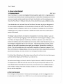
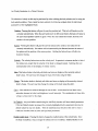
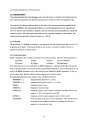
1.3 How does jt work?
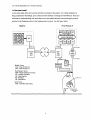
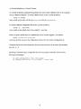
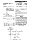
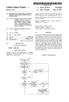
As the name states, there are two main activities occurring in this system. An n-body simulation is
being computed on the Maspar, and a virtual universe interface is running on Pixel-Planes 5. These two
machines are communicating with each other over a semi-public ethemet network using the protocol
specified in the Protocol section of the Implementation manual. See the figure below.
Mas Par
Pixel-Planes 5
vme bus
ethernet
centurion ethernet
VAX
jason
Sun
3520
4/280
(To other HMOs)
Mas Par Terms:
ACU ·Array Control Unit
DPU · Data Parallel Unit
Pixel-Planes 5 Terms:
MGP - Master Graphics Processor
GP- Graphics Processor
HIF- Host Interface
RN • Renderer
FB • Frame Buffer
(tracker sensor)
Other Terms:
HMD • Head-Mounted Display
30
moco~hoadPhoo")
(video screens)
(inside)
4
User's Manual
Mark Parris
1.4 Features
This section discusses some of the features of the nbody system and explains how they may be useful to
the user.
Body Sets
This system supports simulations which have distinct sets of bodies, each set having different features
(see Feature Sets). Two sets of bodies are supported, alpha (or fixed) bodies and beta bodies. Alpha
bodies represent a set from which bodies can be neither added nor deleted. These bodies typically have
an explicit ordering and a set of equations which are applied to the bodies based on that ordering. An
example of such bodies might be the planets in an orbital simulator where each planet has its own
orbital equation. In such a simulation there may be other bodies which are affected by the masses of
the orbital bodies and each other. These bodies could be beta bodies, a second set of bodies where bodies
•
can be added and deleted and manipulated in different ways from the alpha bodies. Note however
that there is no requirement that two sets of bodies be present. A simulation can work entirely with
alpha bodies or entirely with beta bodies. Further, realize that there may be simulations where the
beta bodies can't be added or deleted or both. The ability to manipulate the bodies is determined by
feature sets described below.
Feature Sets
Feature sets define the operations that can or must be performed on a set of bodies or the world. There
are three feature sets, those for the alpha bodies, beta bodies and the world. Alpha bodies and beta
bodies have the same features to choose from with the exception of add and delete. Alpha bodies can
not have either of these properties. Features which a simulation may choose to enable include the
following: change position, velocity, mass, radius, color, or charge; send color or radius; and show
velocity. The change features inform the user interface that the user can change those properties of a
body from the specified set. Alternatively, the send features require the user interface to send
information about those properties when they are changed. Most properties are always sent but a
simulation that is interested in color or radius is uncommon so the default is to not send that information
unless the appropriate send feature is enabled. The show velocity feature is used to let the user
'
interface know whether or not any valid velocity information is generated for the bodies so that the
user interface can display velocity vectors for the bodies from the appropriate set.
In addition to body features, there are also world features including change sample ratio, time step and
interactive sample ratio. These features are not assigned to a specific set of bodies, but rather indicate
that the simulation supports modification of these parameters and whether or not the features are
supported interactively. The simulation and user interface exchange information about body and
5
An N-body Simulation in a Virtual Universe.
feature sets at initialization as part of the protocol that allows them to communicate as described
briefly below.
Note that determination of body sets as well as feature sets is specified in the simulation portion of the
system. If the user wishes to change the system at this level, he will need to be able to modify a
currently existing simulation or write one of his own. For more information, see Writing Your Own
Simulator in the appendix.
Simulations
There is no limitation to use only the Maspar as a simulation engine. The system configuration file
allows any networked computer to handle the simulation. A program on any machine may be used
instead as long as it follows the nbody communications protocol for interacting with the user interface.
Protocol
The simulations provided with this package communicate using a specified protocol, which is
described in the protocol section of the Nbody Implementation Manual. The protocol is implemented in
a library Oibnbp.a) and a sample simulation is provided in
nbody I src/protocol/test/ sample_sim. c. This sample simulation provides a good example of a
basic simulation, including the protocol interaction as well as examples of body and feature sets. The
user may simply insert his own function in this sample to perform calculation of body positions, or he
may use it as a starting point for creating his own simulation.
Scenarios
While the simulation is an actual program implemented to calculate the positions of the bodies over
time (using a chosen numerical method), scenarios are files which simply contain the state of a
particular simulation. These files may include any of the information accessible to the user in normal
editing of the system, e.g. time step, sample ratio, the user's position, and the bodies' orientation,
scaling, body properties, law parameter values, etc. They are basically the 'save file' for the nbody
system. They save the current workspace in an ASCII format which may later be reloaded into the
system. However, they are not tied to the simulation which the user is currently running. Thus, a user
may save a scenario that represents the state of a particular simulation with a given set of input after
some amount of time and then load that scenario into another simulation to see how the same bodies
react under a different simulation.
6
User's Manual
2. How to Get Started
Mark Parris
2.1 Hardware etiquette
Since Pixel-Planes 5 is a one-of-a-kind high-performance graphics engine, there is a high demand for
its processor cycles. Further, because consistent performance is desired from the machine, the front-end
processors (currently machines named 'jason' and 'hugin') should only be used for executing processes
that utilize Pixel-Planes 5. Editing or other such activities should be done using a different machine.
Users should refer to the /etc/mold file on the Pixel-Planes 5 host when they log in to be apprised of
the current machine configuration as well as reservations for demos and the like. Once one is up and
running, he should be considerate of others who may be waiting. An occasional run of 5-10 minutes is
probably okay, but if a longer run is desired it is probably best to pick a time when a small number of
people will be around.
The Maspar is also used heavily for research in the department. Its front-end, 'centurion' also will
display an /etc/mold file upon logging in which will describe the current usage of the Maspar. Unlike
Pixel Planes, the Maspar implements timesharing to distribute its processor cycles. This creates a
problem for the nbody system when multiple users are running. After a certain time slice, the user who
has the Maspar is swapped for the next user in the queue. This means that during run mode, position
updates will stop until the simulation process again gets the Maspar. The time slice is currently ten
seconds. Thus, with multiple users, every ten seconds the simulation will pause for ten seconds. Pixel
Planes will continue to do display updates, so the user may still look or move around, but the simulation
pause becomes annoying. As a result, it is best to use the Maspar when others are not.
It is obvious that a dedicated user of the n-body system will need to select time slots to run the programs
such that both the Maspar and Pixel-Planes 5 are relatively free.
The head-mounted displays are located in both the Graphics Lab and in the HMD Lab (room 262). The
VPL Eyephones in the HMD Lab need to be turned on with the power strip near the north wall. The
Virtual Research helmet should always be powered on, and only needs to have its displays turned on
via the switch on the back of the helmet. Always remember to turn off the head-mounted displays
after you are done using them.
2.2 How to run the prQgram
When running then-body simulator with the head-mounted display, it is best to be logged onto one of
the workstations in the Graphics Lab or HMD Lab to be near the head-mounted display equipment.
7
AnN-body Simulation in a Virtual Universe.
Pixel-Planes 5 has several configurations, and may be reconfigured without advance notice. Thus the
exact unit which is attached to the head-mounted display in the Graphics Lab or HMD Lab on any
particular day is somewhat unpredictable. Fortunately, the members of the HMD group maintain
command scripts which look up the current configuration and set the necessary environment variables
for the desired device.
To start an n-body session, the user must be logged into either 'jason' or 'hugln' depending on how PixelPlanes 5 is configured. Currently, 'hugin' is the host for the head-mounted display in the Graphics Lab,
while 'jason' is the host for the HMD Lab. Logging into one of these hosts can be accomplished via a
simple rlogin.
rlogin jason
To set up the environment variables for the head-mounted display in the Graphics Lab, execute the
following command from the 'jason' or 'hugin' prompt:
source -hmd/bin/glab
To use the unit in the HMD Lab, execute instead:
source -hmd/bin/hmdlab
If executing one of these scripts yields an error message, an incorrect host has been chosen. In this case
the script describes which host to log in to. The user then must then re-source the appropriate shell
script.
Carl Mueller
2.3 A Sample Session
To run the program with the default setup, execute the following command:
nbody
See Appendix B for possible command line options. Several startup messages will be displayed. If you
see the message "Waiting for Pixel-Planes," then another user is currently using the machine. You
should wait until you see the "Command ('q' to quit)" message before putting on the head-mounted
display.
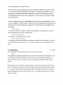
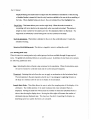
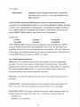
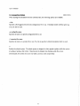
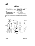
When putting on the VPL Eyephones, simply slide them over your face, and make sure they fit fairly
snugly. The only trick is to make sure you press the plastic back flap back before putting the Eyephones
on. To wear the Virtual Research head-mounted display, twist the knob on the back of the helmet to
loosen the interior halo so that the helmet slides on easily. Then tighten the halo until it fits snugly
and does not wobble.
8
User's Manual
Use this knob to
tighten to head
-.....
VPL Eyephones
Virtual Research Eyephones
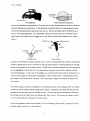
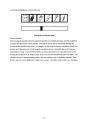
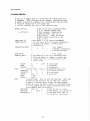
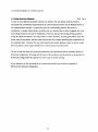
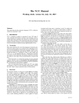
Input to the simulation is generated by a 30 mouse, one of which is positioned next to each of the headmounted displays in the department. Tools (described in details in Section 3 of this document) can be
selected and manipulated by using these input devices. Both the pool balls and the Python3 devices
may be used in this application. For compatibility's sake, both devices only use two buttons (in the
nbody system the Python3 uses the trigger as the "left" button, and the top left button is the "right"
button.).
Start Button--.._
Trigger
Left Button
Pool Ball Mouse
Python 3 Mouse
In general, the left button is used to activate a tool, or select a control panel item, while the right button
is used to change modes, cancel a command, or bring up control panels. To select a general tool, the right
button can be pressed to call up the tool panel. The left button can then be pressed when the appropriate
icon is highlighted to select that tool. If the right button is pressed, no new tool is selected, and the
tool panel disappears. To enact one of the widgets on a control panel the hand needs to be placed in the
vicinity of the widget so that the item is highlighted. When the left button is subsequently pressed,
that widget on the control panel is enacted. (The control panel widgets are described in detail in the
next section.)
After either loading a scenario or building one, the simulation may be run by clicking on the "Go" button
in either the World Editing or Body Editing control panels. The bodies in the setup will obey the rules
specified by the simulation until the simulation stops. The user may stop the simulation by calling up
the tool panel with the right button, and selecting the "Stop" button. The scenario may then be edited
or even reloaded before exercising the simulation again.
To quit the application, either click the skull on the World Editing control panel, or remove the headmounted display and type 'q' at the keyboard.
9
An N-body Simulation in a Virtual Universe.
Again, if you are the last to use the head-mounted display for the day, you should power it off when
you are finished using it. The standard procedure is to either turn off the power strip provided for the
head-mount gear, or, in the case of the Virtual Research Flight Helmet, use the switch on the back of
the helmet.
10
User's Manual
3. The User Interface
Erik Erikson
This section describes in detail the tools and functions available in the user interface for manipulation
of the scenario setup and control of the simulation. All the buttons, sliders, and dials discussed are part
of the virtual interface that is seen in the display. The exceptions to this are references to the physical
3-d mouse.
Again, when this document refers to the 3-d mouse and its buttons, it refers to the pool ball mice. These
mice have a left and a right button. Since the nbody project began, a new 3-d mouse has been added.
This device is called the Python3 and is a joystick with four buttons and a switch. The mapping of our
"left" button is to the Python3's trigger. Our "right" button is the top left button of the Python3 (refer
to the diagram in the previous section).
3.1 Overyjew of the Functions Available to the User
There are two major modes in the interface:
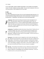
Editing mode - In editing mode the user may adjust the parameters of the n-body simulation.
During editing mode, the simulation is halted so that bodies will remain stationary while
their various attributes are altered. Within this mode, there are two submodes: Body Editing
and World Editing.
Running mode- In running mode the simulation is being updated, and user interaction is more
limited. Only tools affecting the display of the world may be used. Nothing interactive may
occur other than the use of the thrust tool.
3 2 Interface Paradigm
Adam Duggan
The paradigm utilized in the design of the interface is the use of tools and control panels. Control
panels provide a centralized means of executing specific actions or manipulating specific characteristics
of the virtual universe. Tools provide a more direct interaction with the universe and are used for
changing the user's view or directly manipulating the visual characteristics of bodies. The selection of
tools is implemented through the use of the control panels. When a tool has been selected, the user's
mouse pointer changes to represent that tool so the user knows that any action will be in terms of that
tool's function.
11
An N-body Simulation in a Virtual Universe.
3.2.1 Control Panels
The main control panels are those for world editing and body editing modes. Panels also exist for
loading and saving scenarios, simulations, and selecting force laws. These panels have buttons, dials,
and sliders as means of selection and input. Furthermore, they have text displays to give the user
feedback resulting from his actions. Feedback examples are the display of a value as the user is
dynamically changing it or display of filenames. An example of a control panel is shown below for
reference. Note that in the virtual world, the text in this example is replaced with graphic icons.
~c:JD
@]EJEJ
body
choose
law
I
K::Jic:ll
vectors
load
save
scenario
show
disabled
8~[]
load
simularn
i
@]g
B
§:
!
set
set
thrust
time
amount
step
1000000.00
I
Gr.;~
(main slider)
•
I~
~·~~
These control panels will be displayed automatically when the user enters the appropriate mode.
They are defined in room space in the virtual world. Thus, they will translate with the user as he flies
(since flying moves the entire room space about in the virtual world). In addition, they will disappear
during flight to allow easier viewing of the world. Each panel has a grab area around its edge
allowing the user to pick the panel up and orient it as he wishes.
3.2.2 Tool Selection Panels
In addition to the control panels, the user interface also utilizes tool selection panels. These are
specialized control panels, and as such, function differently. purpose is to allow the user a simple
method for changing his current tool in all of the different modes of operation of the system. Since
many possible tools exist (run mode has fly, scale, grab, thrust, sample rate, and stop tools), it is
difficult to create a quick and easy method of switching between them. The Vixen program utilizes the
right mouse button to cycle between tools. However, having any number of tools makes this method
difficult since one must cycle through all of the tools to obtain the tool previous to the current one. As a
result, we chose to implement selection of tools though a "tool selection panel". This is a control panel
which pops up upon pressing the right mouse button. The panel contains only "buttons", one for each of
the possible tools. Any time that the mouse pointer is inside the active volume of one of the buttons,
12
User's Manual
the button will be highlighted. Clicking the right mouse button cancels the tool selection panel, and
the user is returned to his previous state and previous current tool. Clicking the left mouse button selects
the currently highlighted tool. The only time that pressing the right button won't bring up the tool
selection panel is when a body editing tool is currently in use. At this point, the right mouse button
simply cancels the body editing tool and the user is returned to his previous tool.
Example tool selection panel:
Edit Mode Tool Selection Panel
3.3 Mode Features
The following functions are available in the various modes :
Any Editing Modes
•
Select a body by using the selection slider.
•
Go to the selected body.
•
Attach/ detach user from a selected body.
World Editing Mode
•
Add new bodies.
•
Delete bodies.
• Show /hide velocity vectors.
• Show /hide disabled bodies.
•
Select a different interaction function (force law).
•
Change parameters to the interaction function.
• Change the time step of the simulation.
• Start the simulation (go to Running Mode).
•
Load or save a scenario from or to a file.
•
Load a new simulation.
•
Go to Body Editing Mode.
•
Exit the system (quit).
13
An N-body Simulation in a Virtual Universe.
Body Editing Mode
•
Adjust Position (tool).
•
Adjust Radius (tool).
•
Adjust Velocity (tool).
• Adjust Mass (slider).
• Adjust Charge (slider).
• Adjust Color (dials).
•
•
•
•
•
Set the default body.
Disable/enable a body .
Establish the origin body.
Start the simulation.
Go to World Editing Mode .
Running Mode
• Apply an acceleration to a selected body.
• Go to Editing mode (STOP).
• Change the sampling ratio of the display.
Any Mode
• Flying/Translating around the world.
• Grab /Rotate the simulation.
• Shrink/Expand the world.
• Select a body by pointing .
3.4 General Appearance
In this virtual world, the nbody "universe" is defined as one collective object. Thus, the only objects in
the virtual world are the user, the universe, and the control panels. Since the universe is one object, the
user may easily perform positioning, orientation, and scaling operations on the entire universe at one
time.
In the nbody system, different sets of bodies may have certain features turned on or off (see the Features
section). In order to make the user aware of what changes he can or cannot make (and to make the
control panel function smoothly), buttons may be hidden if their feature is turned off by the simulation.
For example, if a body is selected from a body set that does not allow the user to change the position or
radius of the body, those buttons will disappear from the control panel when the user selects that
particular body. This can cause an interesting effect when the user moves the body selection slider and
looks at the control panel at the same time. Different buttons appear and disappear at high rates of
speed.
14
User's Manual
The user has the ability to edit the simulation characteristics as well as display of the simulation
universe. To do this, a collection of tools are available. The way the tools are presented to the user, as
well as their function, is what constitutes the rest of this chapter.
3.5 Iools
3.5.1 Global Tools
These tools are selected from the tool panel, which is invoked by pressing the right mouse button. The
tool itself is selected by pressing the left mouse button when the mouse pointer is in the proper button's
bounding volume. A representation of the editing mode tool selection panel appears below.
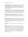
Flying Tool- When the user has the flying tool in hand, the user's hand appears to be an
arrow. When the left button is pressed, the user flies through the virtual world in the
direction pointed by the arrow. The user may adjust the speed of flight by using the hand as a
throttle. The further away the hand is from the head, the faster the user flies through the
virtual world. The speed is signified by the color of the arrow; the arrow changes from blue to
red as the user's speed increases.
Grabbing Tool- The grabbing tool attaches the universe to the user's hand. This allows the user
to reorient the display of the universe, so that the interactions between the bodies may be
viewed from any angle without the user having to perform contortions to position himself
appropriately. Holding the left button keeps the universe grabbed. When the user lets go, the
universe is left at its current location.
Resizing Tool - This tool allow the user to change the size of the universe with respect to the
0
D
user. The universe may be shrunk down to fit in the palm of the user's hand, or enlarged to fill a
football stadium. It functions like a vertical slider, moving down to shrink and up to expand.
Holding the button down will continue scaling in that direction. One important note is that the
'center' of the shrinking or enlarging is at the tool itself. As the universe is scaled up, it scales
away from the tool and thus the increase in size may not always be very apparent.
Select Tool - This tool allows for the selection of a body. With this tool, when the user clicks
the left button, the body that is nearest to the user's hand (the select tool) will be selected.
Selection is indicated by a white highlighter box surrounding the selected body. A body must
be selected in order to use the tools in Body Editing mode.
15
An N-body Simulation in a Virtual Universe.
Edit Mode Tool Selection Panel
3.5.2 Editing Mode Tools
When the user is in editing mode, a control panel is presented to the user. This is an object that is
displayed in the virtual world, and may be manipulated by the user. Currently, the control panels
consist of a set of buttons, sliders, and dials.
The user activates a control panel widget by putting his hand inside the widget's active volume and
pressing the left mouse button. The user can tell when a button is selected by the highlight around it.
This highlight is displayed when the user's mouse pointer is within the active volume for the button.
Pressing the left mouse button while the button is selected either toggles the switch or simply activates
the button, depending on that button's function. For sliders, the left mouse button grabs the slider
handle, and allows the user to adjust that slider's parameter by moving the handle from side to side or
top to bottom (while holding down the left mouse button).
Editing mode has two sub-modes: World Editing mode, and Body Editing mode. World Editing mode
controls parameters that. affect the entire system, such as the simulation's interaction function
constants, time step, thrust, etc. In Body Editing mode, individual characteristics of the simulation
bodies may be altered. Each mode has its own unique control panel.
3.5.2.1 Common Tools for Editing Mode
These tools are available on both the world editing and the body editing panels. See the illustrations
in those sections for locations of these tools on the panels.
Body selection slider - Moving this slider changes which body is currently selected. In conjunction
with the body selection slider , the up and down buttons associated with the slider may be used
to cycle through all of the bodies, highlighting them sequentially so that other editing
commands may be used. Note that as different bodies are selected, buttons on the control panels
will appear and disappear depending on whether the feature associated with that button is
turned on for the selected body.
16
User's Manual
Go to body- This button causes the user to be transported to the location of the currently selected
body.
Attach to/Detach from a body- The attach/detach button may be clicked to indicate that the user
will be attached to the currently selected body once the user enters Running mode. This allows
the user to see the simulation from that particular body's perspective. When the user is
attached to a body, the button will have a full chain showing. By clicking the button again,
the chain will break, and the user is no longer attached to the body. In edit mode, the attached
body is indicated by a pointy box.
3.5.2.2 World Editing Tools
The world editing control panel has the following appearance:
':~i
mode
r::l
~
choose
law
0
U
D
delete
show
body
vectors
;:~
scenario
load
simu!arn
U
LJ fr:-
show 'Ltta_ch_JI r;:l
disabled
l.lisllcl
U
L_j L_j
8
~
~ ~
~~ ...-----. ~
th~~'
amount
:~: ~
I
step
I
1oooooo. oo
I =!7
~g?~l§3;;::::::::::;.~(ma::ln=~~lde:,)::::::::;!~4;~~ij ~
Descriptions of each button and its function is as follows:
Add new bodies- Pressing this button gives the user the Add Tool. With this tool, the left mouse
button creates a new body at the pointer's location in the world. The new body will have
initial attributes specified by the default body, which may be specified in the scenario file or
changed via the body editing panel. The right mouse button is used to cancel the Add Tool.
Delete bodies- Clicking this button will simply delete the currently selected body.
Show /hide velocity vectors - This is simply a toggle the user has available to turn on/ off the
velocity vectors. When showing, the velocity vectors appear as white lines extending from the
surface of the bodies.
17
AnN-body Simulation in a Virtual Universe.
Show /hide disabled bodies - This is also a toggle the user has available to tum on/ off the display
of bodies marked as disabled. When showing, disabled bodies appear surrounded by a blue
highlight box. Disabled bodies may only be displayed in edit mode. When run mode is
invoked, they disappear and have no further effect on the simulation (although this may be
determined by the simulation).
Select the interaction law- A simulation can have several different interaction functions, or laws,
which determine the behavior of the bodies in the simulator. Pressing the Law button brings up
a panel of laws to choose from. A slider is provided to select the law. Pressing the Ok! button
selects the highlighted law, and pressing the world button returns to the world edit panel.
Change the parameters to the interaction function (A.B.C)- It is assumed that the number of
variable parameters to each of these simulation laws is three or less. These three buttons
choose one of the three parameters to alter by using the slider. Use of the slider is discussed
below.
Change the time step of the simulation- This is another parameter of the interaction function that
may be changed. It controls the size of the discrete time steps which are used to update the
simulation. Though this will change the apparent speed of the simulation, it is different than
the sample ratio adjustment available in Running Mode, as changing it may affect the accuracy
of the simulation.
Start the simulation- This causes Running Mode to commence. This button appears as the GO
button.
Loading/Saving a Scenario- Pressing this button brings up another panel. This panel contains
several button, text, and a slider. The text consists of valid scenario names which are in the
current directory. Valid name must have a .nbody extension. The provided slider allows one to
choose a name from the list by scrolling through the list. Pressing the load button (signified by
the disk with an arrow coming out) will load a new scenario from the highlighted file name.
Pressing the save button (signified by the disk with an arrow going in) will overwrite the
highlighted file with the current setup. Pressing the world button (signified by the globe)
returns to the world edit panel.
18
User's Manual
Loadin& a simulation:- This button is pressed to bring up a panel showing the names of the
different simulations which are listed in the configuration file (this file is discussed in another
section of this manual). Once again, the slider may be used to choose a name, the Ok! button
may be pressed to load the highlighted simulation, and the world button may be pressed to
return to the world edit panel.
Go to Body Editin& mode- This button may be pressed to enter body editing mode. It is only
available if a body is currently selected. This button appears as a body.
Quit- Pressing this button exits the system immediately. This button appears as a skull and
crossbones.
The time-step, thrust, and parameter (A,B,C) buttons all use the same slider to change their values.
Pressing one of the buttons turns on the slider and its display and allows the user to change the value for
the selected attribute of the simulation. Along with the slider there are four buttons which change the
range of values the slider represents. Two buttons to the left of the slider move the slider's window of
values to the right and left respectively. The two buttons on the right of the slider double or halve the
range of the slider. By using these four buttons, the slider provides both precision and varying value
ranges.
3.5.2.3 Body Editing Tools
The control panel in this mode has the following arrangement:
c=JDDD!
I~
..
-·~
~
EJ@J
r
i@f~' """ ·~ ·- ~. .
I~sition IEJ Iwl~ity IB I I~
®:~~
0
charge
I
ICJ61
1000000.00
I
(main slider)
19
I~
~g
AnN-body Simulation in a Virtual Universe.
The selection of a body to edit may be performed by either utilizing the body selection tool or using the
body selection sliders. Once a body has been selected, the following widgets affect the individual
parameters of the highlighted body:
Position - Pressing this button will give the user the position tool. This tool will function on the
currently selected body. When the user holds down the left mouse button, the body will jump to
the user's hand position (similar to grab). When the user releases the button, the body will
remain at its new position.
Radius- Pressing this button will give the user the radius tool to create a new radius for the
currently selected body. This radius will be determined ·by the distance between the center of
the sphere and the position of the mouse pointer. Holding the button down will allow for
dynamic resizing.
velocity- The velocity button turns on the velocity tool. It operates in a inanner similar to that of
the radius tool, except that the velocity of the body is changed instead. Selecting this tool
automatically turns on the display of velocity vectors.
Mass- This button hooks to the body edit slider and turns on display of the currently selected
body's mass. The user may then change the mass of the body using the slider.
Charge - This button hooks to the body edit slider and turns on display of the currently selected
body's charge. The user may then change the charge of the body using the slider.
Color- Color selection is achieved through the use of dials. A dial exists for hue (basic color),
saturation (amount of color), and brightness (overall intensity). The combination of these dials
will give a final color for the object.
Set Defaults- Any new bodies created using the Add Body function will have default parameters.
If the Set Defaults button is pressed, the currently highlighted body's parameters become the
default values for any new bodies. With the Add Body tool, this allows the user to create a
whole set of bodies with the same user-specified parameters.
Disable/enable body- Pressing this button changes the enabled status of the current body. Once
the body is disabled, it may no longer be edited until it is re-enabled. Disabled bodies are not
20
User's Manual
displayed during run mode and do not figure into the simulation's calculations. If the showing
of disabled bodies is turned off, then the only function available to the user is the re-enabling of
the body. When disabled bodies are shown, they are indicated by a blue highlighter box.
Origin Body- This button allows you to set the origin body. When this mode is turned on,
everything will move relative to the origin body when run mode is invoked. This makes it
simple to create a center for the system and view the simulation relative to that body. The
origin body is indicated by colored orthogonal axis lines centered on the body.
Start the simulation - This button is identical to the one in the world edit panel. It starts the
simulation running.
Return to World Editing mode- This button is toggled to return to editing the world.
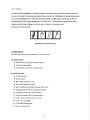
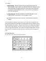
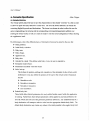
3.5.3 Running Mode Tools
When the user is in running mode, only a select group of tools are available through the pop-up tool
menti. The global tools mentioned before are accessible as usual. In addition, the tool menu now contains
the following additional items:
Stop -Selecting this item will send a stop command to the simulation. When the simulation stops,
the user is returned to world edit mode and the world edit panel reappears.
Thrust tool - Selecting this tool allows the user to apply an acceleration to the last selected body.
The tool operates in the same manner as the fly tool. It is analogous to applying thrusters to
the body as it interacts with the rest of the bodies in the simulation.
Sample Ratio Slider - This slider allows the user to select the sampling ratio of the display of the
simulation. The middle position of the slider indicates that every calculated frame is
displayed. Moving the slider left will increase the number of times each calculated frame is
shown, thus slowing the display down. Moving the slider right will increase the number of
calculated steps per displayed step. This may have the effect of speeding the display up,
depending upon how quickly the frames are calculated.
21
An N-body Simulation in a Virtual Universe.
IBII I f!J I !? I f Ill
I
I
I
Run Mode Tool Selection Panel
Note on run mode:
Since running the simulation involves communication between multiple processes, ensuring completely
successful synchronization can be difficult. Although the nbody system successfuJiy handles this
synchronization, problems may occur. For example, the user might be testing a simulation of their own
creation, and a bug may occur which hangs the simulation process. NormaJiy, this would cause the
whole system to hang. To prevent this problem, an "undocumented feature" was added to the system.
Pressing the top button of the Python3 input device will cause the simulation process to be killed. This
will aJiow the user to return to editing mode in the user interface (with no simulation running). Thus,
the user need not exit the application to begin a new session. He simply needs to load a new simulation.
22
User's Manual
4. Scenario Specification
Adam Duggan
4.1 Scenario Oymriew
The n-body system allows the user to save the characteristics of his created "universe" in a file in order
to allow for quick and easy retrieval at a later time. The save file format utilized is an ASCII file
containing English keywords and declarations. This format was chosen in order to allow the user the
option of generating a the universe and its corresponding environmental parameters without ever
entering the virtual world, as well as to make it simple to edit the saved configuration without starting
the application itself.
The following is a list of the different pieces of information that may be stored in the save file:
• Body positions.
• Initial body velocities.
• Body mass.
•
Body charge.
•
Apparent size.
• Body color.
•
Attached to a body. This defines what body, if any, the user is attached to.
• Simulation model choice.
• Parameters associated with that model.
• Initial set-up.
This defines the position, scaling, and orientation of the simulation in the virtual world;
furthermore it may also define the position of the user in the virtual world. Parameters
maybe:
• Simulation scale.
• Simulation orientation.
• Simulation translation.
•
User translation.
• Default body info.
These fields define default parameters for newly added bodies created while the application
is running. Furthermore, these default parameters will be applied to any body defined in the
save file which does not have that particular parameter defined (i.e. any undefined field in a
body declaration will attempt to take its value from the appropriate default body field.) The
default body declaration may contain any subset of the fields possible in the regular body field.
23
AnN-body Simulation in a Virtual Universe.
4.2 Language Specifks
This section describes the actual language of the state file format. It contains a list of keywords and
their respective arguments, and describes each keyword's function as well as the argument's type.
The units for all values are defined relative to the units of the function parameters specified in the
declaration MODEL. This keeps things flexible by not restricting arguments to be in a specific unit.
However, the user must remember to keep all of his units consistent across declarations, or undesirable
results may ensue. All of the numeric parameters may be expressed in integers or real numbers. Real
numbers may be expressed in scientific notation (i.e. 1.23E-45).
4.2.1 Comments
The pound sign "#"designates a comment. Any characters after this character anywhere on a line will
be ignored by the parser. This feature should be used to place a descriptive header in the file in
addition to comments on specific entries.
4.2.2 Body Specification
BODY : Designates start of specific information for a particular body. May have following fields for:
[1] Position
[3] Mass
[5] Color
[7] User attached?
[2] Velocity
[4] Charge
[6] Radius
[8] Origin body?
These fields may occur in any order after the BODY designation. All fields pertaining to this specific
body are declared inside a set of braces
0 following the BODY declaration.
If any of these fields do not
occur in the BODY declaration, they will be read from the DEFAULT_BODY declaration. If they do
not exist there, then "default" defaults will be assigned by the n-body system.
The following specifications are possible within a BODY declaration:
POSmON x y z:
Designates body position in x, y, and z.
VELOCITY x y z :
Designates body initial velocity in x, y, and z.
MASSm:
Designates a body's mass.
CHARGEq:
Designates a body's charge.
COLORrgb:
Designates a body's color in terms of red, green, and blue values (in the
range of 0- 255). Note that this is not HSV.
RADWSr:
Designates a body's radius (apparent size) in virtual world.
ATIACHED
Define this body as the one the user is attached to. This command must
be specified inside a BODY declaration, indicating that the user is
attached to that particular body.
24
User's Manual
ORIGIN_BODY:
Designates this body as the origin of the universe. In run mode, all
other bodies will move relative to it. Also must be specified inside a
BODY declaration.
DEFAULT_BODY: Similar to the BODY declaration, except this command defines the default
parameters of a newly generated body created by the user while the application is running. This makes
it simple to have a consistent manner of body generation. This statement is not required. If it does not
exist, a "default" default will be imposed by the user interface. These fields may occur in any order
after the DEFAULT_BODY statement. Again, all fields must be inside braces (}.
Possible fields:
[!]MASS
[3]COLOR
[5] VELOCITY
[2]CHARGE
[4] RADIUS
[6]POSillON
NOTE: DEFAULT_BODY will also be used by the application to fill in any blanks left in a BODY
declaration which follows the default body specification in the save file. The final default body
specification will be the one used as the initial default in the user interface. Thus, if it is desired that
all bodies have a set of identical characteristics, they need only be specified once. (This implies that
an empty BODY declaration is allowed, i.e. BODY (} is accepted.)
4.2.3 World Environment Specification
MODEL expr (abc}: Define the model to be used in this simulation, as well as its corresponding
parameters. The value for expr is equal to the label defined for the desired model. Thus, possible
arguments may be words such as 'gravity', 'electro', 'gravity+electro', 'gravity_cubed', etc., depending
upon what the available simulations expect. a, b, and care the model's constants. There may be
between zero and three of these constants, depending on the model.
TIME_STEP x : This declaration defines the time step at which the simulation function performs its
calculations.
SAMPLE_RATIO x : This declaration defines how many time steps to make per visual update of the
system. Thus, with a value of 60, we get 60 time step iterations before we do a visual update.
SIMULATION_SETUP (V_xform_type): Designate the simulation's initial orientation, scaling, and
translation relative to the origin of the virtual world. v_xform_type is a structure of the form:
translation: x y z
orientation: x y z w (quatemion)
25
An N-body Simulation in a Virtual Universe.
scale: s
These values will be explained further here. (See sample file for example.)
USER_SETUP x y z : Specify the user's initial translation relative to the origin of the virtual world.
May be floats or integers.
26
User's Manual
4.3 Sample State File
# This is a sample file to illustrate the n-body save file
# language.
This file sets up two masses, one orbiting the
# other, along with a default for creating more masses which
# would be satellites of the larger one.
# It also attaches the user to the orbiting mass.
MODEL gravity
{ 6.673E-20
TIME STEP 30
SAMPLE RATIO 2
SIMULATION SETUP
USER SETUP
DEFAULT BODY
# Set up for just a gravity model
# (i.e. inverse square law).
# Only parameter required for
# gravity model. This is in
# krn'3/kg*s'2.
Thus, all other
# definitions should be in km,
# kg, s, etc.
# Set delta t to 30 second increments.
#In this case (with 30 second increments),
# display the results of every other
# calculation.
0
0
0
# At origin.
1
0
0
0
# Normal orientation.
1
# Normal scaling.
0
0
0
# At origin.
# The default is set as a satellite body
# This now makes it simple to create new
# bodies that are all satellites of the
# 'main' body.
COLOR
MASS
RADIUS
0
0
200
# solid blue
10
# kilograms
10
# kilometers
BODY {
# First body.
This is the massive center one.
POSITION
0
0
0
# at center of sim.
VELOCITY
0
0
# no velocity.
0
COLOR
200
0
0
# solid red
MASS
1.0E6
RADIUS
1000 )
BODY {
# Second body. This is the orbiting one. With the
# position and velocity set as they are, should
# remain in stable orbit around the center mass.
# Does not have any MASS, COLOR, or SIZE specified,
# so the system obtains these characteristics from
# the
POSITION
VELOCITY
ATTACHED TO
DEFAULT BODY declaration.
1000 0
0
# 1000 krn out on x axis.
0
3000 0
# 3000 krn/sec in y direction.
)
# indicates that user is
# attached to this body.
27
An N-body Simulation in a Virtual Universe.
5. Thanks
Thanks to the following people for their assistance:
Russ Taylor - libsdi.a, libconvert.a
Jim Chung- Use of text in a virtual world.
Mark Wetzel (UT)- Astronomy information.
Jack Wisdom (MIT)- Astronomy information.
HMD team- vlib, head mount support.
Pixel-Planes team - Pixel-Planes libraries.
Clients - Support in getting access, defining project. Providing creative freedom.
Boss - Pointers to resources, disk space.
Facilities, David Harrison, Video Crew
28
User's Manual
Appendices
Mark Parris
A. Process Configuration Specification
There are several ways to specify the name of the program to run as the simulation process as well as
the machine to run it on. This was desired in order to allow the user the flexibility of running the
simulation on different machines, as well as providing the ability to run different simulation programs.
Thus, multiple simulations may exist, each utilizing different numerical methods to generate the
simulation data or even to run a different kind of simulation as long as it follows the specified protocol.
These differences will be invisible to the user interface portion of the system as long as all simulations
use a consistent protocol to communicate with the user interface. (See the Protocol section of the
Implementation Manual.)
The default configuration is to use the Maspar front-end machine to run the simulation program named
"siml" (ann-body simulation). This information is found in a file called config_file. The program uses
the first entry in it to get the process to run and the machine to run it on. An entry in the file is a single
line consisting of a one word tag, the name of the machine to run the process on, and the full pathname
of the program to run on the remote machine along with any arguments. A sample file follows. Each
entry is one line.
Sample file:
# This is the default simulation to run on the Maspar
# The current Maspar front-end is called centurion.
siml centurion /unc/parris/nbody/parris/net/src/proto/psim -a -b
# This is the model of the solar system that uses
*solar_sim
standard elliptical orbits.
degas /unc/parris/nbody/parris/net/src/solar/solar
# This is a simple model where bodies orbit in rings
# around one another
rings centurion /unc/parris/nbody/parris/net/src/rings/rings
The remote process should expect to be called with the arguments specified in the file appended to two
arguments which are sent by the display program. These are the name of the machine on which the
display process is running and a port number which the display process is listening to. (The arguments
here are illustrative only.) All other information should be passed via the protocol once the connection
is established.
29
An N-body Simulation in a Virtual Universe.
To override the default, command line parameters are used to select a different entry in the con fig file
and/ or a different config file. To choose a different entry use the -e switch as follows:
nbody -e nbodyO
which would use the entry with the tag solar_sim in the file config_file.
To choose a different configuration file use the -p switch as follows:
nbody -p .. /myconfig
which would use the default entry in the config file .. /myconfig.
Finally, to select a specific entry in a different file use the switches together. For instance:
nbody -p this.cnf -e my_sim
would use the entry my_sim in the configuration file this.cnf in the current working directory.
Comments may be used in this document in the same manner that they can be used in the simulation
state file, i.e. '#'.
Specifying a nonexistent tag or configuration file results in program termination with one of the
following error messages:
No such configuration file: <file name>
No configuration entry in <file name> : <entry tag>
30
User's Manual
Mark Parris
B. Command Une Qptions
When starting the simulation from the command line, the following options are available:
-e tag
Specifies which tagged entry from the configuration file to use. If multiple entries with the same tag
exist, the first is used.
-p config._file_name
Specifies the name of a process configuration file to use.
-f scenario_file_name
Specifies the name of a scenario file to use. If no file is specified a default simulation (siml) is used.
-r
Enables the refresh system. The refresh system is designed to allow graphic updates while the system
is loading or saving a file to disk. This prevents the display from freezing while this occurs.
Unfortunately, the system is not yet very stable, and may crash unexpectedly.
31
An N-body Simulation in a Virtual Universe.
C. Writing Your Own Simulator
Mark Parris
In order to use a different simulation with the user interface the user simply needs to provide a
simulation that can fulfill the requirements of the communication protocol (see the Protocol section of
the Implementation Manual). In particular, given the handshaking protocol that occurs at
initialization, a simple orbital tracker can inform the user interface that it doesn't support any of the
body editing functions, but only the modification of the time step and the sending of body positions.
Using this simple simulation a user may attach to a body and ride it, fly among the bodies, resize the
bodies, scale the simulation, and any other functions that don't require modifying the computations of
the simulation itself. However, the user could reset the time step to produce a faster or slower model.
Other simulations which support different sets of the functions could be created.
The user would then need only to place the pathname of this simulation and any necessary options in
the process configuration file along with the name of the machine to run the process on (as specified in
the Process Configuration File appendix) in order to get the system running.
Several references to data and methods of computing simulations are provided in appendix F,
References for Astronomy Information.
32
User's Manual
D. Using the Nbody Debug Libwy for Scenarip Creation:
Adam Duggan
One of the libraries created by the nbody team for use in debugging and scenario file generation has
possible uses for the end user as well. Anyone wishing to create systems with large numbers of bodies
and who does not wish to build them by hand (in the virtual universe or even with a text editor) may
benefit from the use of this library. A function call exists for every possible type of output to the
scenario file, and the output of the functions is in the correct file format recognized by the nbody
system. Thus, the user may set up his own code to generate the bodies in some systematic fashion. Then,
when he is ready to create the resulting scenario file he may simply call the routines with his
appropriate data structures, and the result will be a scenario file guaranteed to be in the proper format.
The team actually used this method in generation of many of its sample scenario files, and it has
proven to be a useful method. The function headers follow for easy reference. The first parameter of
each is a file pointer to which the proper output will be written.
To print a body:
print_body (FILE *fp, BodyType *body)
To print a default body:
print_default_body(FILE *fp, BodyType *body)
To print a body list:
print_body_list(FILE *fp, BodyListType *bodies,
short num_bodies, ScenarioType *scenario)
To print the scenario information (time step, laws, etc.):
print_scenario( FILE *fp, ScenarioType *scenario)
To print the user setup and the simulation setup:
print_xforms(FILE *fp, v_xform_type *sim_xform, q_vec_type user_xform)
For the exact formats of the data types, see nb_types. h and vlib.
33
An N-body Simulation in a Virtual Universe.
E. Future Directions
Some features that would be nice to incorporate into this application are the following :
• Include Alert panels that show up in front of the user when an error occurs. The user would then
have the opportunity to clean up and save the current scenario.
• Additions to the protocol, including the possibility of dynamic thrust updates (having the two
sides of the system synchronize when thrusts are being applied).
• The ability for the user to change directories from within the head-mounted display, and
perhaps enter new file names.
• A more accurate simulation on the Maspar, and the possibility of more complicated and computeintensive simulations. The current n-body simulation was not taxing the Maspar as is, and more
complex interactions might prove interesting.
• A Solar System simulation. This involves researching some orbital data, and making the
simulation more accurate or more tailored to such a simulation.
• An audio cue to the user when he strays from under the tracker's effective range.
• Possibly include both fine and coarse control for changing a bodies' velocity.
• Any operations which involve deleting data should have appropriate warning sounds and
confirmation actions to be initiated.
34
User's Manual
F. References for Astronomy Informatjon
In writing this simulation we gathered several references to astronomical data and methods which
could be used for writing an orbital simulation. They are provided below as a reference for writing your
own simulation.
Texts on Celestial Mechanics:
Roy, A.E. Orbital Motion
Danby, J.M.A. Fundamentals of Celestial Mechanics
Analytic expressions for orbits:
Van Flandern, T.C. and Pulkkinen, K.F. "Low-Precision Formulae for Planetary Positions"
Astrophysical Jounal Supplement Series, vol. 41, pp. 391-411, November 1979.
Numerically Tabulated Ephemerides at JPL :
Contact: Dr. E. Myles Standish ([email protected])
Initial Conditions:
Quinn, Tremaine, and Duncan. Astron. J. 101,2287 (1989)
Algorithms for computing celestial mechanics:
Wisdom and Holman. Astron. J. 102, 1528.
35
An N-body Simulation in a Virtual Universe.
Index
Running Mode Tools 21
Sample Ratio Slider 21
Sample State File 27
SAMPLE_RATIO 25
Scenario Specification 23
Select the interaction law 18
Select Tool 15
Set Defaults 20
Show /hide disabled bodies 18
Show /hide velocity vectors 17
simulation process 29
SIMULATION_SETUP 25
Start the simulation 18
Stop 21
Thrust tool 21
TIME_STEP 25
USER_SETUP 26
Velocity 20, 24
World Editing Tools 17
Writing Your Own Simulator 32
3-Dmousedevice3
Add new bodies 17
Attach to/Detach 17
ATIACHED24
BODY24
Body Editing Tools 19
Body selection slider 16
Change the parameters 18
Change the time step 18
Charge 20, 24
Color20,24
Command Line Options 31
config_file 29
control panel16
Debug Library 33
default configuration 29
DEFAULT_BODY 25
Delete bodies 17
Disable/ enable body 20
display program 29
Editing Mode Tools 16
ethemet 4
Flying Tool 15
Future Directions 34
Global Tools 15
Gotobody17
Grabbing Tool15
head-mounted display 2
HMD3
hugin 7
jason7
Loading a simulation 19
Loading/Saving a Scenario 18
Maspar 3
Mass20, 24
MODEL25
n-body simulation 2
Origin Body 21
ORIGIN_BODY 25
Pixel-Planes 5 3
port number 29
Position 20, 24
print_body 33
print_body_list 33
print_default_bod 33
print_scenario 33
print_xforms 33
Radius 20, 24
Resizing Tool 15
Return to World Editing mode 21
36