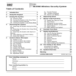
1
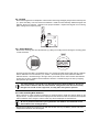
WLS900 Wireless Security System
Table of Contents
5L - Trouble Present
5M - Trouble Conditions
5N - Sensor Low Battery
10
11
11
1
Introduction
2
2
Using the Keypad
3
3
Arming the System
4
6
Bypassing Zones
12
4
4
4
5
7
Master Code Functions
13
3A - Arming Levels;
3B - Arming the System in the Away Mode
3C - Improper Arming Warning
3D - Arming the System in the Home Mode
4
Disarming the System
6
4A - Disarming the System During the Entry
Delay
6
4B - Disarming the System from Away Mode
or Home Mode
6
4C - Disarming the System with Alarms In
Memory
6
4D - Alarm Memory and Alarm History
7
4E - Quick Exit Feature
7
5
System Status Messages
5A - System In Use
5B - Communications Successful
5C - Communications Cancelled
5D - Fire Troubles
5E - Sensor Faults
5F - Tamper Faults
5G - System Not Ready
5H - No Response From Controller
5I - System Ready
5J - Alarms in Memory
5K - Bypassed Zones
7A - Setting the Date and Time
7B - Door Chime
7C - Changing Access Codes
7D - Replacing System Components
7E - Alarm History
7F - Walk Testing Your System
8
Sounder Functions
18
9
Replacing Batteries
19
9A - Tips for Buying Batteries
9B - Required Batteries
9C - Door or Window Sensor
9D - Sounder
9E - Motion Detector
9F - Keypad
9G - Smoke Detector
9H - After Installing New Batteries
8
8
8
8
8
9
9
9
9
10
10
10
13
14
14
15
16
16
10
Fire Safety in the Home
22
Household Fire Safety
Family Escape Planning
11
22
22
System Overview
23
Warning
Limited Warranty
19
19
20
20
20
21
21
21
24
Inside rear cover
Your installing company is,
Name: ______________________________________________________________
Address: ____________________________________________________________
Phone: ______________________________________________________________
Your monitoring station is,
Name: ______________________________________________________________
Phone:
1
1
INTRODUCTION
Congratulations on your selection of the DSC WLS900 Wireless Security System. The WLS900 Wireless
Security System has been designed to provide you with a dependable and flexible security system that is
easy to operate and maintain. The system uses radio signals to link its components together. Wireless
technology allows for great flexibility in locating the system’s components; only the controller and the
sounders need to be located where they can be plugged into an electrical outlet.
Each of the system’s components is designed to perform a specific function within the security system.
The Keypad is the part of the system you will be using the most; it is used to arm and disarm the
system, and to display messages about system operation. The keypad screen displays messages in
plain language to tell you what the system is doing, and to guide you through system operation.
The Controller contains the electronics that control the security system. When an alarm is generated, the
controller will activate the Sounder and will, if programmed to do so, contact your monitoring station to
report the alarm. The controller can be located anywhere a telephone line connection and an electrical
outlet is available. Along with its electrical transformer, the controller also has a rechargeable backup
battery that will operate the system should there be a power failure.
The Sounder is used to alert you when an alarm has occurred. The sounder is also used to indicate
with various sounds that certain system activities are being performed. The sounder should be located
centrally so that it may be heard clearly when it is activated. The sounder requires an electrical outlet
for its transformer.
Motion detectors are designed to detect the movements of an intruder. Motion detectors will generate
an alarm if they detect motion when the system is armed. Care should be taken not to block the view of
your motion detectors. If you can't see them they can't see the intrudor. Your installer will tell you where
motion detectors have been installed and what areas they protect.
Door or Window Sensors are used to indicate when a door has been opened. If a door or window
sensor is activated when the system is armed, an alarm will sound. A sensor can also be set by your
installer to have “entry/exit delays”. These delays allow time for you to activate a sensor when entering
or leaving the premises without causing an alarm. Your installer will tell you where door or window
sensors have been installed, and which sensors have these delays.
Smoke Detectors sound an alarm when smoke from a fire is detected. The fire detection part of your
security system is designed to provide you with an early warning of a possibly dangerous situation; your
installer will explain to you how your fire detection system works and how it should be maintained. For
more information write to the NFPA, One Batterymarch Park, Quincy MA 02269
02269, to request more
information about life safety devices and where they should be located.
Test Your System Regularly
To ensure that your system continues to function as intended, it is important that you test your system
regularly. Refer to “Walk Testing Your System” in the Master Codes section of this manual, and read and
follow the instructions carefully. If your system does not function properly or if you have any questions
about testing your system, call your installer for service or assistance.
Important Notice
A security system cannot prevent emergencies. It is only intended to alert you of an emergency
situation. Security systems are generally very reliable but they may not work under all conditions
and they are not a substitute for prudent security practices or life and property insurance. Your
security system should be installed and serviced by qualified security professionals who should
inform you of the level of protection that has been provided, and instruct you on system operations.
2
2
USING THE KEYPAD
The Keypad is designed to make your system easy to use. Messages describing system status and
operation are displayed on the Keypad screen in plain language, an easy to follow menu will guide you
through all aspects of system operation. Operating the system is as easy as answering “Yes” or “No” to
the questions presented on the Keypad’s screen.
The Keypad’s Inactive State
When the keypad is not being used, it will be in an inactive state to conserve its batteries. When inactive,
the screen will be blank. Note that the keypad will automatically return to its inactive state after 30
seconds if no keys are pressed. To wake up the keypad and begin to operating the system, press the
key and then enter your personal Access Code.
Adjusting the Keypad Screen Contrast
With the keypad in its inactive state, press . When this message is
displayed, you may adjust the contrast of the screen display by pressing and
holding the
or
Keys. Press and hold
to increase the contrast, and
to decrease the contrast. When adjusted as desired, enter your personal
Access Code.
Using the Keys
The keys on the Keypad are used as described below:
Number Keys
to and are used to enter Access Codes to arm and disarm the system. The Number
Keys are also used to change Access Codes and set the Date and Time.
Arrow Keys
and
are used to answer “Yes” and “No” to questions displayed on the Keypad, and
to display or select system options and functions. Use
to answer “Yes”, and
to
answer “No”. The Arrow Keys are also used to move from one screen to another; moving
Key to “scroll” forward to the
from one screen to another is called “scrolling”. Use the
next screen, use the
Key to select the option displayed on the screen.
Key
The Key is used to cancel an incorrect entry. For example, if you make a mistake while entering
your Access Code, press to clear the mistake, and then enter your Access Code again.
The Key is also used to return to the beginning of a list of Menus. While scrolling through
Key to return to the beginning of the list.
a list of options, press the
Key
To activate a Fire Alarm*, press and hold the
Key for 2 seconds; this will activate
a loud pulsing or loud steady alarm (your installer will inform you of how the alarm will
sound). To silence an
Key alarm, enter your Access Code. If programmed by your
installer, the alarm will be reported to your monitoring station.
Key
To activate an Auxiliary Alarm*, press and hold the
Key for 2 seconds; this will
activate a silent alarm (the Sounder will not be activated). If programmed by your installer,
the alarm will be reported to your monitoring station. When the alarm has been reported
to the monitoring station, the Sounder will sound several beeps.
Key
To activate a Panic Alarm*, press and hold the
Key for 2 seconds. If programmed
by your installer, this will send a report to your monitoring station. This alarm may be
programmed as a silent alarm; your installer will inform you of whether or not the Sounder
will be activated when the
Key is pressed. To silence a
Key alarm, enter your
Access Code.
*May not be programmed if keypads are in a public place.
3
3
ARMING THE SYSTEM
3A - Arming Levels;
The system is designed for simple and easy arming.
“Disarmed”
“Home”
“Away”
- When the system is “Disarmed”, it is still providing protection with,
1. keypad emergency buttons, P, A, or F,
2. smoke or fire detection devices,
3. possibly 24-hour sensors for special cabinets, closets, drawers, etc.
- When the system is armed to “Home”, it allows you to move around freely without
concerns but touching specific doors or windows may cause the system to sound.
- When the system is armed to “Away”, all protection is “Active”.
You cannot bypass smoke or fire devices.
Your system may be set up by your installer to arm in a mode other than the Away Mode or the Home
Mode. If this is the case, your installer will provide instructions on how to arm your system, and how your
system functions while armed.
3B - Arming the System in the Away Mode
The Keypad will normally be in an inactive state to conserve its batteries.
and the Keypad will wake up.
Press
Enter your personal Access Code using the Number Keys. As each digit of
the code is entered, an “X” will appear on the Keypad screen. If a mistake
Key to clear the
is made while entering the Access Code, press the
mistake and re-enter the Code.
If the system is ready to be armed, this message will be displayed for a few
seconds, then the next message will be displayed. If the system is not ready
to be armed the keypad will alert you of any conditions. See Section 5 of this
manual for further discriptions.
To arm the system in the Away Mode, press the
-YES Key when this
message is displayed. If the system is armed in Away Mode, all zones will
be active when the system is armed.
-YES Key is pressed, the Exit Delay will begin and this
When the
message will be displayed for a few seconds. With 30 seconds remaining
in the Exit Delay, the Sounder will begin to “beep” once every second.
During the last 10 seconds of the Exit Delay, the Sounder will “beep”
twice every second. At the end of the Exit Delay, the Sounder will be
silenced and the system will be armed.
3C - Improper Arming Warning
If a loud error tone sounds when you arm the system, re-enter your personal Access Code to silence the system.
Check the keypad to see if a sensor, has been left open. Close the zone, and then re-arm the system.
4
The Improper Arming is designed to prevent false alarms by warning you when your system has been
improperly armed. If a Zone, such as Door or Window Sensor, is left open when the system is armed, an error
tone will sound. The error tone will sound for the duration of the Entry Delay time. If the system is not disarmed
before the Delay expires, an alarm will be reported to your monitoring station.
3D - Arming the System in the Home Mode
The Keypad will normally be in an inactive state to conserve its batteries.
Press
and the Keypad will wake up.
Enter your personal Access Code using the Number Keys. As each digit of
the code is entered, an “X” will appear on the Keypad screen. If a mistake
is made while entering your personal Access Code, press the Key to clear
the mistake and re-enter the Code again.
If the system is ready to be armed, this message will be displayed for a few
seconds. After a few seconds, the next message will be displayed. If the
not ready to be armed
armed”, or if there are conditions on the system
system is, “not
of which you should be aware, other messages may be displayed; refer to
Section 5 of this manual for further discriptions.
- YES Key when this
To arm the system in the Away Mode, press the
message is displayed. To display the next message or to arm the system in
the Home Mode, press the
-NO Key.
To arm the system in the Home Mode, press the
- YES Key when this
message is displayed. If the system is armed in Home Mode, only some
of the sensors in your system will be active when the system becomes
armed. This option is designed to allow you to remain on the premises while
the system is armed. Zones that cover the interior of the premises will not
cause an alarm if activated, but zones that cover most entry points, such as
windows and doors, will sound an alarm if they are activated. Your installer
will tell you which zones are automatically bypassed when the system is
Home Mode
armed in the “Home
Mode”. When this message is displayed, press the
YES Key to arm the system in the Home Mode. If you want to bypass zones,
press the
-NO Key.
Home Mode
When the
- YES Key is pressed to arm the system in the “Home
Mode”,
this message may be displayed. To arm the system and enable the Entry
Delay, press the
- YES Key. With the Entry Delay turned on, activating an
Entry/Exit Zone will start the Entry Delay. When the Entry Delay begins, a
personal Access Code must be entered to disarm the system. To arm the
-NO Key. With the Entry
system with the Entry Delay turned off, press the
Delay off, activating an entry zone will sound an alarm immediately.
When the
- YES or
-NO Keys are pressed, the Exit Delay will begin
and this message will be displayed for a few seconds. With 30 seconds
remaining in the Exit Delay, the Sounder will begin to “beep” once every
second. During the last 10 seconds of the Exit Delay, the Sounder will “beep”
twice every second. At the end of the Exit Delay, the Sounder will be silenced
and the system will be armed. If you have not left the building, you must
disarm and then re-arm the system.
5
4
DISARMING THE SYSTEM
If the system is in alarm when you arrive, do not enter the premises; an intruder may be
present or a fire condition may exist. Go to a neighbor and contact the authorities from
there. Only if you are absolutely certain that no danger exists should you proceed with
disarming the system and entering the premises.
4A - Disarming the System During the Entry Delay
Enter the premises through your designated Entry/Exit door. The Sounder
will start a steady tone to indicate that the Entry Delay has started. An alarm
will sound if you do not disarm the system before the Entry Delay expires.
The Keypad will be in its inactive state. Press and the Keypad will display
the next message.
Enter your personal Access Code using the Number Keys. As each digit of
the code is entered, an “X” will appear on the Keypad screen. If a mistake
is made while entering your personal Access Code, press the Key to clear
the mistake and re-enter the Code.
When your personal Access Code is entered, this message will be displayed
to indicate that the system is disarmed and no alarms occurred while the
system was armed. After a few seconds, the Keypad will return to its inactive
state.
4B - Disarming the System from Away Mode or Home Mode
When your personal Access Code is entered, the Keypad will display a
message similar to this to indicate the system is armed in either the Away or
Home Modes. In this example, the system is armed in the “Home Mode”. This
message will be displayed for a few seconds.
If the system was armed with the Entry Delay shut off, this message will be
displayed for a few seconds. After a few seconds, the next message will be
displayed.
After indicating which Mode the system is in, the Keypad will ask if you wish
-YES Key to disarm the system.
to disarm the system. Press the
If no alarms occurred while the system was armed, the Keypad will display
this message to indicate that the system is disarmed. After a few seconds,
the Keypad will return to its inactive state.
4C - Disarming the System with Alarms In Memory
This message will be displayed if an alarm occurred while the system was
armed. This message will be displayed for a few seconds, then the next
message will be displayed.
If there are alarms in memory, this message will be displayed. Press the
NO Key to return the Keypad to its inactive state, or press the
-YES Key
to view the Zones in Alarm Memory. When viewing Alarm Memory, use the
-YES Key to scroll through the list of zones that went into alarm.
6
When scrolling through the Alarm Memory Display, the screen will display
messages like the one shown here. The Zone that went into alarm will be
displayed, along with a message asking if you would like to view the next item
-YES Key to view the next Zone in Alarm Memory, or
in the list. Press the
-NO Key to return the Keypad to its inactive state. When the last
press the
-YES or
Zone in Alarm Memory has been displayed, pressing either the
-NO Key will return the Keypad to its inactive state.
4D - Alarm Memory and Alarm History
Alarm Memory provides a record of Zones that went into alarm during the time the system was armed.
The next time you arm the system, the Alarm Memory will be cleared and the events in Alarm Memory will
be recorded in Alarm History. Any old events in Alarm History will be cleared when Alarm Memory is
recorded as Alarm History.
Alarm History retains a record of Zones that appeared in Alarm Memory. When Alarm Memory is
cleared, Alarm History will record the Zones that had been displayed as Alarm Memory. You can
refer to Alarm Memory and Alarm History to determine if certain Zones repetitively sound alarms.
Refer to “Viewing Alarm History” in the System Status Messages, Section 5J of this manual for
information on viewing Alarm History.
When Alarm Memory and Alarm History are viewed, the Keypad will display
the Zone Labels for the zones that went into alarm. The example here shows
-YES Key to view other zones that went
Zone 1 went into alarm. Press the
into alarm.
Alarms activated by pressing the
,
or
Keys on the
Keypad will be indicated with messages similar to the one shown here.
4E - Quick Exit Feature
The Quick Exit feature is designed to allow you to exit the premises without sounding an alarm while the
system is armed. This feature must be enabled by your installer before it may be used. Your installer will
tell you if this feature has been enabled on your system.
With the system armed, enter your personal Access Code. The Keypad will
display a message similar to the one shown here.
-NO Key. When you
When the Keypad displays this message, press the
press the
-NO Key, the next message will be displayed.
Press the
-YES Key to activate the Quick Exit feature. When Quick Exit
is activated, you will be allowed up to two minutes to exit the premises. During
the two minute period, you may exit the premises through the designated
Entry/Exit door.
You may activate the Entry/Exit Zone only once; re-entering will start the Entry Delay.
7
5
SYSTEM STATUS MESSAGES
When arming your system, certain messages may be displayed on the Keypad after your personal
Access Code has been entered. These messages are designed to inform you of conditions that may
affect system operation. Messages will only appear if the conditions they indicate are present.
5A - System In Use
While two Keypads may be installed on your system, only one Keypad may
be used at a time. If one Keypad is presently being used, this message will
be displayed if a key is pressed on the other Keypad.
5B - Communications Successful
This message will be displayed when a personal Access Code is entered
after the Controller has successfully communicated with the monitoring
station. For example, if a personal Access Code is entered after an alarm has
occurred and been reported to the monitoring station, this message will be
displayed to indicate that the alarm has been reported.
5C - Communications Cancelled
communications
Zones on your system may be programmed with a “communications
reporting delay
delay“ to cancel false alarms before they are reported to your
monitoring station. Refer to the System Overview inside rear cover for more
information. Your installer will indicate which Sensors, if any, have an Alarm
Reporting Delay.
To cancel a false alarm, enter your personal Access Code when the alarm
sounds. For example, if a sensor is accidentally activated, you can cancel
the report to the monitoring station by entering your Access Code. The
message shown here will be displayed.
The Communications Cancelled message will also be displayed when you
disarm the system after an Improper Arming Warning has sounded.
5D - Fire Troubles
This message will only be displayed if problems with a Fire Sensor are
A Fire Trouble
detected. “A
Trouble” may mean that a Fire Detector’s batteries are
running low, or that the detector may require service.
This message will be displayed, and then the next message will scroll onto
the display.
-YES Key to view the list of Fire Troubles. Check the sensors
Press the
indicated to ensure that their batteries are installed properly.
If you require assistance, or if Fire Troubles occur often, contact your installer immediately.
8
5E - Sensor Faults
Sensor Faults
This message will only be displayed if “Sensor
Faults” are detected. A
Sensor Fault may mean that a Sensor’s batteries are running low, or that the
Sensor is unable to communicate with the Controller. This message will be
displayed before scrolling to the next message.
-YES Key to view the list of “Sensor
Faults”. Use the
-YES
Press the
Sensor Faults
Key to scroll through the list of Sensor Faults. Check the Sensors indicated
to ensure that their batteries are installed properly. If you require assistance,
or if Sensor Faults occur often, contact your installer.
5F - Tamper Faults
This message will only be displayed if the system detects a Tamper
condition. An open Tamper condition may indicate that a component has
been removed from its normal location, or has been interfered with. This
message will be displayed before scrolling to the next message.
-YES Key to view the list of “Tamper
Faults”. Use the
-YES
Press the
Tamper Faults
Key to scroll through the list of Tamper Faults. When finished viewing the list
of Tamper Faults, press the
-NO Key. Check the components indicated to
ensure that they are mounted properly. If you require assistance, contact your
installer.
5G - System Not Ready
This message will only appear if the system is not ready to be armed
because one or more zones are open. A zone is “open”, if, for example, a
protected Door or Window is improperly secured. Zones will be indicated
as “open” if they have a Tamper or Sensor Fault. Refer to the Tamper Fault
in Section 5F or Sensor Fault in Section 5E for information on viewing these
conditions. This message will be displayed automatically.
-YES Key to view the list of Open Zones; press the
-YES Key
Press the
again to scroll through the list of Open Zones. When finished reviewing the
-NO Key to return to the “View Open Zones Y/N?” message.
list, press the
With this message displayed, press the
message.
-NO Key to display the next
-YES Key. To continue without bypassing
To bypass zones, press the
-NO Key. For instructions on bypassing zones, refer to
zones, press the
Bypassing Zones, Section 6.
5H - No Response From Controller
This message will be displayed if the Keypad is unable to communicate with
the Controller. This message will be displayed and, then the Keypad will
return to its inactive state. If the Keypad displays this message often:
• ensure the Controller’s adaptor is properly connected and plugged in
• ensure the Keypad’s batteries are not reporting “Low Battery” and are
properly installed
• if you require assistance, contact your installer.
9
5I - System Ready
This message will be displayed when a personal Access Code is entered and
the system is ready to be armed.
5J - Alarms in Memory
If there are alarms in memory, this message will be displayed before arming.
When the Keypad displays this message allowing you to arm the system,
-YES Key to arm the system, or press the
-NO Key. To view
press the
-NO Key until the next message is displayed.
alarms in memory, press the
-YES Key to view “alarm memory”. Refer to Alarm Memory and
Press the
Alarm History in Section 4D for instructions on reviewing alarms in memory.
5K - Bypassed Zones
This message will be displayed if zones on the system have been bypassed.
Refer to Bypassing Zones in Section 6 for information on viewing bypassed
zones.
5L - Trouble Present
A “trouble” is a condition that may cause the system to operate improperly;
refer to the “Trouble Conditions” in Section 5M. When trouble conditions are
reported, they should be investigated immediately. When a trouble condition
is present, the Sounder will beep a warning. Enter your personal Access
Code to silence the trouble indication. When your personal Access Code is
entered, this message will be displayed.
When the Keypad displays a message allowing you to arm the system, press
-YES Key to arm the system, or press the
-NO Key. To view trouble
the
-NO Key until the next message is displayed.
conditions, press the
Press the
-YES Key to view trouble conditions on the system. Your system
may be armed with trouble conditions present, but be aware that the system
may not perform as expected with the troubles present. When viewing
-YES Key to scroll to the next trouble
trouble conditions, press the
-NO Key.
condition. When you are finished reviewing the list, press the
10
5M - Trouble Conditions
The system monitors itself automatically for trouble conditions. Your system may still be armed with a
trouble condition present, but beware the system may not operate as expected. If you were unable to
correct a trouble condition, contact your installer for assistance.
Trouble Display
Cause
What You Should Do
“Controller Batt”
“Controller Battery”. Low backup
battery in the Controller
Call your installer for assistance
“Controller AC”
AC power supply to the Controller
has been interrupted
Ensure Controller transformer is
plugged in. If this does not correct
the problem, call for service
“Sounder 1 AC Flt”
AC power supply to the First Sounder
has been interrupted
Ensure Sounder’s transformer is
plugged in to the wall outlet and the
unit itself. If this does not correct
the problem, call for service
“Sounder 2 AC Flt”
AC power supply to the Second Sounder
has been interrupted
Ensure Sounder’s transformer is
plugged in to the wall outlet and the
unit itself. If this does not correct
the problem, call for service
“Telephone Line”
Telephone line connection has
been broken or disconnected
Ensure the telephone line is plugged
into the Controller. If this does not
correct the problem, call for service.
“Fail to Com”
“Failure to Communicate”.
The Controller has been unable to
call the monitoring station
Call your installer for assistance
“Loss of Clock”
Controller has lost both AC and
battery power, and upon power up
has a loss of clock (clock is reset)
Refer to Section 7A for instructions
on resetting the clock. If this is not
possible, call for service
5N - Sensor Low Battery
This message will be displayed if sensors on the system report low batteries.
This message will be displayed before allowing you to arm the system.
When the Keypad displays a message allowing you to arm the system, press
-YES Key to arm the system, or press the
-NO Key to view the list
the
of sensors with low batteries.
Press the
-YES Key to view the list of sensors with low batteries. When
-YES Key to scroll
viewing the list of Sensors with low batteries, press the
to the next Sensor. When you are finished reviewing the list, press the
NO Key. Your system may be armed when sensors report low batteries.
Sensors with “Low Battery” conditions may stop functioning while the system is armed.
Any Sensor that reports “Sensor Low Batt” should have its batteries
replaced. Refer to “Replacing Batteries” in Section 9 for information on the
types of batteries to use in each Sensor, and for instructions on how to install
them.
11
6
BYPASSING ZONES
A “bypassed” sensor will not cause an alarm. Sensors may be bypassed to allow access to part of the
premises while other sensors remain armed. For example, you could bypass the motion sensor
protecting your living room, while the sensor protecting the Entry/Exit Door remains armed. Bypassed
sensors will be automatically cleared the next time you disarm the system. Each time you want to arm the
system with some of the sensors bypassed, follow the procedure below.
Bypassed sensors will not cause an alarm. Before arming the system with bypassed sensors, be
sure to review the list of bypassed zones and ensure that all bypasses have been made
intentionally.
This message will be displayed allowing you to bypass sensors, view
previously bypassed sensors, or to clear sensors that are already bypassed.
This message will be displayed as part of the arming procedure. When asked
-NO Key until this message is displayed.
to arm the system, press the
When this message is displayed, press the
or to clear existing bypasses.
-YES Key to bypass sensors
-YES Key is pressed, the Keypad will display a message similar
When the
-YES Key. To display the next
to this one. To bypass the sensor, press the
sensor, press the
-NO Key.
When the
-YES Key is pressed, this message will be displayed. The
sensor is now bypassed; to clear the bypass, press the
-YES Key. To
-NO Key.
display the next sensor, press the
If a sensor is open while the system is in the Bypass Sensors mode, a
OP
message similar to this one will be displayed. Note that the “OP
OP” indicates
-YES Key to bypass the sensor, or
that the sensor is opened. Press the
press the
-NO Key to display the next sensor.
Fire zone cannot be bypassed.
12
7
MASTER CODE FUNCTIONS
The Master Code is a unique personal Access Code that allows you to make changes to some of the
programming features in your system. In addition to arming and disarming the system, the Master Code
also allows you to:
•
•
•
•
•
•
Set the Date and Time
Enable and Disable the Door Chime Feature
Add, Remove, and Change, Access Codes
Replace System Components
View Alarm History
Perform a Walk Test of the System
Only the Master Code will allow you to change the functions listed above; normal Access Codes are not
able to change system features. When scrolling through the list of Master Code Function Menus, you
Key to return to the “System Ready” message.
may press the
To enter the Master Code Functions Mode, enter your master code and respond to each question until
the screen goes blank.
7A - Setting the Date and Time
-YES Key to reset the Date and Time, or press the
-NO Key
Press the
-YES Key is pressed, the following
to display the next option. When the
message is displayed.
Using the Number Keys, enter the Date with 2 digits for the Month, 2 digits
for the Day and 2 digits for the Year. For example, the date of March 4 1996
would be entered as 030496. If an error is made in entering the Date, press
the Key and the Keypad will display the “Reset Clock Y/N” message; press
the
-YES Key and enter the correct Date. When the complete Date is
entered, the next message will be displayed.
Using the Number Keys, enter the Time in using the 24-hour clock format. For
example, the time 1:15 pm would be entered as 13:15. If an error is made in
entering the time, press the
Key and the Keypad will display the “Reset
-YES Key and re-enter the correct Date
Clock Y/N” message; press the
and then the Time. After the Time is entered, the next message will be
displayed.
The Date and Time you have just entered will be displayed on the screen; in
this example, the Date is March 4 1996, and the Time is 1:15 pm. If a mistake
-YES Key to rehas been made in entering the Date or Time, press the
enter the Date and Time as described above. If the Date and Time are
correct, press the
-NO Key to enter the next Master Code Function.
13
7B - Door Chime
When the Door Chime feature is enabled, activating certain sensors will cause the Sounder to beep
several times. The Door Chime is a convenient feature that may be used to indicate that an out-of-sight
door or window is being opened. Your installer will indicate which sensors on your system will work
with the Door Chime feature. Note that the Door Chime only operates when the system is disarmed.
-YES Key to enable the Door
When this message is displayed, press the
Chime feature. When the Door Chime is enabled, the Sounder will beep when
certain sensors are activated, and again upon closure.
This message will be displayed when the Door Chime has been turned on.
When this message is displayed, press the
Chime feature.
-YES Key to disable the Door
This message will be displayed when the Door Chime has been turned off.
7C - Changing Access Codes
Key to “edit Access Codes”, or press the
-NO Key to display
Press the
Key is pressed, the next message will be
the next function. When the
displayed.
The screen will display which of the 10 personal Access Codes have been
programmed. Codes that have already been programmed will be represented
with a dash (-). In this example, Codes 0, 1, 2 and 3 have been programmed;
while codes 4, 5, 6, 7, 8, and 9 have not yet been programmed.
-YES Key to add a new code or change a code that has already
Press the
been programmed. The Keypad will display the next message.
Select which of the 10 personal Access Codes, 0 to 9, that you wish to change
or program by pressing that Number Key. In this example, Access Code 4
key, the Keypad will display the
will be programmed. After pressing the
next message.
Enter the new Access Code using the Number Keys. As each digit is
entered, an “X” will appear on the screen. If a mistake is made in entering
the code, press the Key to clear the entry, and enter the code again. After
you have entered the new code, the Keypad will display which codes have
been programmed.
14
The Keypad will again display which of the 10 personal Access Codes have
been programmed. In this example, note that a dash now appears in place
of Code 4 to indicate that it has been programmed.
-YES Key to add a new code or change a code that has already
Press the
-NO Key is
been programmed using the method just described. If the
pressed, the following message will be displayed.
-YES Key to erase an Access Code. The Keypad will display
Press the
the following message:
Enter the number of the personal Access Code you wish to erase using one
of the Number Keys. That code will be erased, and the Keypad will again
display which of the 10 Access Codes have been programmed. To leave
Edit Access Code mode
-NO Key twice.
the “Edit
mode”, press the
Code “0”, the Master Code, can be changed but that it cannot be deleted.
If the Master Code is forgotten, contact your installer for
assistance.
7D - Replacing System Components
At some time it may become necessary to replace a component on your system, such as a Door or
Window Sensor, Motion Sensor, etc. This could be because a unit is malfunctioning in some way, or has
been damaged through handling or tampering. You should only replace components on the advice of
Replace
your installer. Along with the instructions here, your installer will tell you how to get to the “Replace
System Components Screen”
Screen”.
While in the Component Replacement Mode, the system will not generate or report alarms
for any zones or devices.
When the Keypad displays this message, press the
-YES Key to replace
-NO Key to move to the next
a component on the system or press the
Master Code Function mode.
The Keypad will display the first component that may be replaced and ask
-NO Key to display the next component,
if you wish to replace it. Press the
-YES Key to replace the component displayed on the screen.
or press the
The Keypad will display this message and wait for two minutes for you to
-YES Key. When the
-YES Key
remove the component and press the
is pressed, the Sounder will beep and the next message will be displayed.
15
When this message is displayed, enter the new component’s Serial
Number on the Keypad. Each component’s Serial Number is printed on
the back of the component. If an error is made in entering the number,
Key and re-enter the number. When the Serial Number is
press the
entered, the next message will be displayed, now add Batteries to the
new component.
Confirm that the Serial Number has been entered correctly by pressing
-YES Key. If an error has been made in entering the Serial
the
Key and re-enter the number.
Number, press the
When the
-YES Key is pressed, this message will be displayed and
the Keypad will wait two minutes for you to attach the new component to its
backplate. After the component is attached to its backplate, the next
message will be displayed.
If the component was replaced correctly, the Keypad will display this
message and the Sounders will beep twice. You may now continue with other
Master Code functions.
Key
During the component replacement procedure, you may press the
Key is pressed, this
to cancel the replacement procedure. When the
message will be displayed.
7E - Alarm History
Alarm History is a record of the last set of alarms that occurred on your system. You can use the Alarm
History display to determine which sensors caused alarm. If unintentional alarms are a problem, you can
use the Alarm History feature to help determine which sensors are the problem.
Remember that the Alarm Memory provides a record of which sensors caused alarms during the last
armed period. Each time you arm the system, the Alarm Memory is cleared.
The Alarm History retains a record of sensors that appeared in the Alarm Memory. When Alarm
Memory is cleared, Alarm History will record the sensors that had been in Alarm Memory.
When this message is displayed, press the
sensors in Alarm History.
-YES Key to view the list of
-YES Key is pressed, the first sensor in Alarm History will be
When the
-YES
displayed with a message similar to the one shown here. Press the
-NO Key to
Key to display the next sensor in Alarm History, or press the
cancel the display.
7F - Walk Testing Your System
It is important that you test your system regularly to ensure that it is operating properly. Your installer will
instruct you on how to perform a thorough test of your system, and will also tell you how often to test your
system.
16
A “Walk Test” is a simple procedure designed to make sure all Sensors on your system are working.
• Start the test from the Keypad as described here.
• Walk through the premises to activate Motion sensors.
• Open and close doors and windows to test Door or Window Sensors.
• Smoke Detectors are tested by removing the unit from its backplate and then replacing it.
Refer to the notes on the next page about Testing the Motion Sensors installed on your system.
When a Sensor is activated, the Sounder will sound a series of beeps.
While the system is in the Walk Test Mode, the Sensors will not generate alarms and systems will
not be reported to the monitoring station. Because of this, be sure to cancel the Walk Test Mode
when you have completed the test.
Only the
,
and
Keys remain active while the system is in the Walk Test Mode. If the
,
or
Keys are pressed while the system is in the Walk Test Mode, an alarm will be
generated and reported to the monitoring station.
-YES Key to perform
When the Keypad displays this message, press the
a Walk Test of your system, or press the
-NO Key to return the Keypad
to its inactive state.
The Keypad will display this message for the duration of the walk test. When
a Sensor is activated, the Sounder will sound a series of beeps.
Important: During a walk test, your system will not go into alarm, even
when 24-Hour sensors are activated. When the walk test is complete,
press the
-YES Key and the Keypad will return to its inactive state.
Reviewing the Walk Test
As each Sensor is activated during the walk test, each activation will be recorded in the Alarm Memory.
Review the Alarm Memory to ensure that each Sensor reported to the system when it was activated.
Refer to “Alarms in Memory” in Section 5J for instructions on viewing the Alarm Memory.
Testing Motion Sensors
The motion sensors on your system are designed to require a 6 minute lockout after signaling the system
of an activation. This means that they will only trip once and look for 6 minutes if no motion before they
will activate again. This is done to conserve battery life.
Testing Motion Sensors is done in two steps:
1 Remove the Motion Sensor from its backplate (refer to Replacing Batteries in Section 9E for
instructions on how to remove the Motion Sensor from its backplate). When the Motion Sensor is
removed, the Sounder will beep. After the beep, replace the Motion Sensor on its backplate. This
test ensures that the Motion Sensor is communicating properly with the System.
If you cancel the test without replacing all the Motion Sensors on their backplates, the Keypad will
indicate that there are Tamper Faults on the system. Refer to “Tamper Faults” in Section 5F for
instructions on reviewing tamper faults. If tamper faults are indicated after you finish the test, check
all the Motion Sensors to be sure that they are mounted properly on their backplates.
2 When the Motion Sensor is replaced on its backplate, the detector will be in “test mode” for the next
90 seconds. During the 90-second test period, the detector’s red light will come on each time the
Motion Sensor detects motion. To test the sensor, walk around the perimenter of the room or area
noting that the red light on the sensor keeps flashing on and off as you move.
17
After the test period has ended, the Motion Detector will automatically end its test mode and return
to normal operation. (Later versions of Motion Sensors may stay in “test mode” for 3-4 minutes.)
Questions About Your Walk Test?
If you are ever unsure about testing your system, or if the Walk Test reveals that a Sensor is not working
properly, contact your installer for assistance.
Motion Sensors are trap protection for rooms or areas. They are designed to break the room or
area into small wedges of detection. The best detection occurs while crossing or moving across
the sensors fingers of detection. Discuss your specific protection requirements with your installer
to assure proper detection.
8
SOUNDER FUNCTIONS
The Sounder operates at several different levels to indicate: Intrusion Alarms, Fire Alarms and other
system operations. Many of the sounds the Sounder can produce are programmable by your installer;
your installer will inform you of which sounds have been programmed for which alarms. The possible
alarms and indications from the Sounder are described below:
Event
Sound
Notes
Entry / Exit Delay
Exit Delay: pulsing beeps
Entry Delay: steady tone
Medium or low volume
Your installer will tell you if your
Entry/Exit Delay Tone has been
set for medium or low volume.
Trouble Conditions
Sensor Faults
Tamper Faults
Double “beep” at medium or
low volume every 10 seconds
This tone is used to indicate that there is
a trouble condition on the system. Refer to
the Trouble Conditions, Sensor Faults and
Tamper Faults Section 5 of this manual.
Fire Alarm
Loud pulsing alarm, or
Loud steady alarm
Your installer will inform you of how the Fire
Alarm will sound on your system
Intrusion Alarm
Loud steady or
Loud pulsing alarm, or
Silent
Your installer will inform you if any zones
have been programmed to generate a
silent alarm. Zones set for silent operation
will not cause the Sounder to operate,
but will transmit an alarm to your monitoring
station if programmed to do so.
Key
Loud pulsing alarm, or
Loud steady alarm
To silence an
Key alarm, enter an
personal Access Code
Key
Silent alarm
When the
Key alarm is reported
to your monitoring station, the Sounder
will sound a series of beeps.
Key
Silent or
Audible alarm
To silence a
Key alarm, enter an
personal Access Code.
18
9
REPLACING BATTERIES
From time to time, the batteries in the Sensors and other components on your system will need to be
changed. Your Keypad will indicate when a Sensor’s batteries need to be replaced; refer to Sensor Low
Battery in Section 5N or Sensor Faults in Section 5E of this manual.
Under normal conditions, the batteries in your system should last up to three years. When batteries need
to be replaced in a component, follow the instructions in this Section of the manual, being sure to note the
proper orientation of the batteries as they are installed. Also, when batteries in one component need to
be replaced, it is suggested that the batteries in all components be replaced at the same time.
The sounder batteries provide for short-term operation in the absence of AC power. After any prolonged
AC power interruption(s), replacement of all sounder batteries may be required.
All of the batteries used in the security system are common size Eveready Alkaline Energizer batteries
available anywhere batteries are sold.
Put your system into Walk Test before changing batteries in the sensors! This prevents false alarm
signals from being transmitted to your central monitoring station. See Section 7F “Walk Testing
your System”.
9A - Tips for Buying Batteries
• Your system is designed to work with Eveready Alkaline Energizer Batteries. When replacing
batteries, be sure to buy the same brand and type of batteries. Do not replace the batteries on your
system with any other type. The reliability of your security system depends on its batteries, and “no
name” or generic brand batteries may not provide the best quality and dependability.
• Use fresh batteries. Most batteries have a “best before” date printed on their packaging or on the
batteries themselves. Buy batteries that have a “best before” date of two years or more from your
purchase date.
• When disposing of used batteries, follow the instructions and precautions printed on the batteries.
Many cities and communities have collection sites or services for used household batteries. Contact
your municipal offices for information on the disposal of used batteries.
• If in doubt about the batteries used in your system, or if you have trouble installing them, contact your
installer for assistance.
9B - Required Batteries
Required Eveready Alkaline Energizer Batteries
Door or Window Sensor
Motion Detector
3 AAA batteries
4 AAA batteries
Sounder
4 AA batteries
Keypad
4 AA batteries
Smoke Detector
6 AA batteries
19
9C - Door or Window Sensor
WLS905: Insert a small screwdriver in the slot on the side of the Transmitter. Gently turn the screwdriver
clockwise and pull the module to the left.
WLS907: Insert a small screwdriver into the slot on the side of the Sensor. Push the screwdriver in and lift
off the cover.
Remove the batteries from the module, and install three fresh Eveready Alkaline Energizer AAA batteries.
Be sure to insert the batteries in the proper orientation. Re-assemble the Sensor.
9D - Sounder
Remove the Sounder from its backplate. Pull the bottom of the Sounder slightly away from the wall and push
up. Remove the batteries from the Sounder and install four fresh Eveready Alkaline Energizer AA batteries. Be
sure to insert the batteries in the proper orientation. Replace the Sounder on its mounting plate, making sure it
snaps into place. Be sure that the sounder transformer is properly connected after the batteries are installed
(since the batteries will be automatically powering the sounder whenever AC power is disconnected).
9E - Motion Detector
Remove the Motion Detector from its mounting plate by holding the Sensor by its sides and pushing up.
Remove the batteries from the Sensor and install four fresh Eveready Alkaline Energizer AAA batteries.
Be sure to insert the batteries in the proper orientation. Replace the Sensor on its mounting plate, making
sure it snaps into place.
20
9F - Keypad
Remove the Keypad from its backplate. Pull the bottom of the Keypad slightly away from the wall and push
up. Open the battery cover and remove the batteries. Install four fresh Eveready Alkaline Energizer AA
batteries. Be sure to insert the batteries in the proper orientation. Replace the Keypad on its mounting
plate, making sure it snaps into place.
9G - Smoke Detector
Remove the mounting plate from the detector by pushing the locking tab and turning the mounting plate
counter-clockwise.
Hold the unit with the battery compartment facing you, and the imprinted wording right-side up. Install the
first two batteries in the row nearest to you, with the + terminals facing left. Next, install the middle two
batteries with the + terminals facing to the right. Place your thumb over the centre of these four batteries
to keep them in place. Install the last two batteries, with their + terminals facing to the left, by snapping
them past the nylon retainer.
The smoke detector is designed to use Eveready Energizer Alkaline Batteries. Do not use
other brands of batteries with the smoke detector. Using brands other than the Eveready
Energizer will void UL and ULC approvals, and may affect the system's operation.
9H - After Installing New Batteries
Refer to Section 5 of this manual for information on displaying Sensor Faults and Tamper Faults on the
Keypad screen. A Tamper Fault should be displayed for each Sensor that was removed from its backplate
when its batteries were changed; a Sensor Fault may also be displayed for these Sensors.
Be sure to perform a walk test of your system after new batteries are installed to ensure
that all Sensors are working properly.
Replacing the batteries and performing the walk test will also clear any Low Battery, Sensor Fault, and
Tamper Fault indications from the Keypad.
21
FIRE SAFETY IN THE HOME
Most fires occur in the home, to minimize this danger it is recommended that a household fire safety audit
be conducted and a family escape plan be developed.
Household Fire Safety
Check your home for the following potential hazards:
• Are all electrical appliances and outlets in a safe condition? Check for frayed cords, over-loaded
lighting circuits, and so on. If you are uncertain about the condition of your electrical appliances or
household electrical service, have a professional evaluation.
• Are all flammable liquids stored safely in closed containers in a well ventilated and cool area?
Cleaning with flammable liquids, such as gasoline, should be avoided. Refer to product instructions,
printed warnings and labels for information on using and storing hazardous materials safely.
• Are fire hazardous materials (such as matches) well out of the reach of children?
• Are furnaces and wood burning appliances properly installed, clean, and in good working order? If in
doubt, have a professional evaluation.
Family Escape Planning
There is often very little time between the detection of a fire and the time at which it becomes deadly.
Because of this, it is very important that a family escape plan be developed, practised and followed.
1 Every family member should participate in developing the escape plan.
2 Study the possible escape routes from each location within the house. Since many fires occur at
night, special attention should be given to the escape routes from sleeping quarters.
3 It is essential that escape from a bedroom be possible without opening the interior door. Consider the
following when making your escape plans:
• Make sure that doors and windows that open to the outside are easily opened. Ensure that they are
not painted shut and that their locking mechanisms operate smoothly.
• If opening an exit or using an exit is too difficult for children, the elderly or handicapped, plans for
rescue should be developed. This includes making sure that those who are to perform the rescue
can promptly hear the fire warning signal.
• If the exit is above ground level, an approved fire ladder or rope should be provided, as well as
training in its use.
• Exits on the ground level should be kept clear. Be sure to remove snow from exterior patio doors in
winter. Outdoor furniture or equipment should not block exits.
• The family should have a predetermined meeting place where everyone can be accounted for; for
example, across the street or at a neighbour’s house.
• Once everyone is out of the house, call the Fire Department.
• A good plan emphasizes quick escape. Do not investigate first or attempt to fight the fire, do not
attempt to rescue belongings as this takes up valuable time. Once outside, do not re-enter the
house. Wait for the fire department.
• Write the plan down and rehearse frequently, so that should an emergency arise, everyone will know
what they are to do. Revise the plan as conditions change; for example, when there are more or
fewer family members in the home, or if there are physical changes to the house.
• Make sure your alarm system is operational by conducting weekly tests as noted in this manual. If
you are unsure about system operation, contact your installer.
• It is recommended that you contact your local fire department and request further information on
home fire safety and escape planning. If available, have your local fire prevention officer conduct an
in-house fire safety inspection.
• For more information contact NFPA Standard 72 - National Fire Protection Association, One
Batterymarch Park, Quincy MA 02269
22
SYSTEM OVERVIEW
Protected Areas
Sensor
Area / Location
1
2
3
4
5
6
7
8
9
10
Keypad 1
Keypad 2
Sounder 1
Sounder 2
______________________________
______________________________
______________________________
______________________________
______________________________
______________________________
______________________________
______________________________
______________________________
______________________________
______________________________
______________________________
______________________________
______________________________
Access Codes
Code
Sensor Type
Reporting Delay
_____________________
_____________________
_____________________
_____________________
_____________________
_____________________
_____________________
_____________________
_____________________
_____________________
_____________________
_____________________
_____________________
_____________________
_____________________
_____________________
_____________________
_____________________
_____________________
_____________________
Programmed 4-Digit Code
Person Using Code
0
_______________________
Master Code
1
_______________________
___________________________________________
2
_______________________
___________________________________________
3
_______________________
___________________________________________
4
_______________________
___________________________________________
5
_______________________
___________________________________________
6
_______________________
___________________________________________
7
_______________________
___________________________________________
8
_______________________
___________________________________________
9
_______________________
___________________________________________
Sounder Operation
Key:
Loud pulsed tone
Key:
Key:
Loud steady tone
Silent
Audible Alarm
Silent Alarm
Entry Delay
You have _____________ seconds to disarm the system when entering the premises. If you do not disarm
the system within this time, an alarm will sound! If an alarm sounds, enter your personal Access Code.
Exit Delay
You have _____________ seconds to leave the premises after arming the system. If you do not leave the
premises within this time, an alarm will sound! If an alarm sounds, enter your personal Access Code.
23
WARNING Please Read Carefully
Note to Installers
This warning contains vital information. As the only individual in contact
with system users, it is your responsibility to bring each item in this warning
to the attention of the users of this system.
System Failures
This system has been carefully designed to be as effective as possible. There
are circumstances, however, involving fire, burglary, or other types of emergencies where it may not provide protection. Any alarm system of any type
may be compromised deliberately or may fail to operate as expected for a
variety of reasons. Some but not all of these reasons may be:
■ Inadequate Installation
A security system must be installed properly in order to provide adequate
protection. Every installation should be evaluated by a security professional
to ensure that all access points and areas are covered. Locks and latches on
windows and doors must be secure and operate as intended. Windows, doors,
walls, ceilings and other building materials must be of sufficient strength
and construction to provide the level of protection expected. A reevaluation
must be done during and after any construction activity. An evaluation by
the fire and/or police department is highly recommended if this service is
available.
■ Criminal Knowledge
This system contains security features which were known to be effective at
the time of manufacture. It is possible for persons with criminal intent to
develop techniques which reduce the effectiveness of these features. It is
important that a security system be reviewed periodically to ensure that its
features remain effective and that it be updated or replaced if it is found that
it does not provide the protection expected.
■ Access by Intruders
Intruders may enter through an unprotected access point, circumvent a
sensing device, evade detection by moving through an area of insufficient coverage, disconnect a warning device, or interfere with or prevent the proper operation of the system.
■ Power Failure
Control units, intrusion detectors, smoke detectors and many other security
devices require an adequate power supply for proper operation. If a device
operates from batteries, it is possible for the batteries to fail. Even if the
batteries have not failed, they must be charged, in good condition and installed correctly. If a device operates only by AC power, any interruption,
however brief, will render that device inoperative while it does not have power.
Power interruptions of any length are often accompanied by voltage fluctuations which may damage electronic equipment such as a security system.
After a power interruption has occurred, immediately conduct a complete
system test to ensure that the system operates as intended.
■ Smoke Detectors
Smoke detectors that are a part of this system may not properly alert occupants
of a fire for a number of reasons, some of which follow. The smoke detectors
may have been improperly installed or positioned. Smoke may not be able to
reach the smoke detectors, such as when the fire is in a chimney, walls or roofs,
or on the other side of closed doors. Smoke detectors may not detect smoke
from fires on another level of the residence or building.
Every fire is different in the amount of smoke produced and the rate of
burning. Smoke detectors cannot sense all types of fires equally well. Smoke
detectors may not provide timely warning of fires caused by carelessness
or safety hazards such as smoking in bed, violent explosions, escaping gas,
improper storage of flammable materials, overloaded electrical circuits, children playing with matches or arson.
Even if the smoke detector operates as intended, there may be circumstances
when there is insufficient warning to allow all occupants to escape in time to
avoid injury or death.
■ Motion Detectors
Motion detectors can only detect motion within the designated areas as
shown in their respective installation instructions. They cannot discriminate between intruders and intended occupants. Motion detectors do not
provide volumetric area protection. They have multiple beams of detection and motion can only be detected in unobstructed areas covered by
these beams. They cannot detect motion which occurs behind walls, ceilings, floor, closed doors, glass partitions, glass doors or windows. Any
type of tampering whether intentional or unintentional such as masking,
painting, or spraying of any material on the lenses, mirrors, windows or
any other part of the detection system will impair its proper operation.
Passive infrared motion detectors operate by sensing changes in temperature. However their effectiveness can be reduced when the ambient temperature rises near or above body temperature or if there are intentional or
unintentional sources of heat in or near the detection area. Some of these
heat sources could be heaters, radiators, stoves, barbeques, fireplaces, sunlight, steam vents, lighting and so on.
■ Warning Devices
Warning devices such as sirens, bells, horns, or strobes may not warn
people or waken someone sleeping if there is an intervening wall or door.
If warning devices are located on a different level of the residence or
premise, then it is less likely that the occupants will be alerted or awakened. Audible warning devices may be interfered with by other noise
sources such as stereos, radios, televisions, air conditioners or other appliances, or passing traffic. Audible warning devices, however loud, may
not be heard by a hearing-impaired person.
■ Telephone Lines
If telephone lines are used to transmit alarms, they may be out of service or busy
for certain periods of time. Also an intruder may cut the telephone line or defeat
its operation by more sophisticated means which may be difficult to detect.
■ Failure of Replaceable Batteries
This system’s wireless transmitters have been designed to provide several
years of battery life under normal conditions. The expected battery life is a
function of the device environment, usage and type. Ambient conditions such
as high humidity, high or low temperatures, or large temperature fluctuations may reduce the expected battery life. While each transmitting device
has a low battery monitor which identifies when the batteries need to be
replaced, this monitor may fail to operate as expected. Regular testing and
maintenance will keep the system in good operating condition.
■ Insufficient Time
There may be circumstances when the system will operate as intended, yet the
occupants will not be protected from the emergency due to their inability to
respond to the warnings in a timely manner. If the system is monitored, the
response may not occur in time to protect the occupants or their belongings.
■ Compromise of Radio Frequency (Wireless)
Devices
Signals may not reach the receiver under all circumstances which could
include metal objects placed on or near the radio path or deliberate
jamming or other inadvertent radio signal interference.
■ Inadequate Testing
Most problems that would prevent an alarm system from operating as intended can be found by regular testing and maintenance. The complete system should be tested weekly and immediately after a break-in, an attempted
break-in, a fire, a storm, an earthquake, an accident, or any kind of construction activity inside or outside the premises. The testing should include
all sensing devices, keypads, consoles, alarm indicating devices and any
other operational devices that are part of the system.
■ System Users
A user may not be able to operate a panic or emergency switch possibly due
to permanent or temporary physical disability, inability to reach the device
in time, or unfamiliarity with the correct operation. It is important that all
system users be trained in the correct operation of the alarm system and that
they know how to respond when the system indicates an alarm.
■ Component Failure
Although every effort has been made to make this system as reliable as possible,
the system may fail to function as intended due to the failure of a component.
■ Security and Insurance
Regardless of its capabilities, an alarm system is not a substitute for property or life insurance. An alarm system also is not a substitute for property owners, renters, or other occupants to act prudently to prevent or minimize the harmful effects of an emergency situation.
NOTICE: The Industry Canada label identifies certified equipment. This certification means that the equipment meets
certain telecommunications network protective, operational and safety requirements. Industry Canada does not
guarantee the equipment will operate to the user’s satisfaction.
Before installing this equipment, users should ensure that it is permissible to be connected to the facilities of the local
telecommunications company. The equipment must also be installed using an acceptable method of connection. The
customer should be aware that compliance with the above conditions may not prevent degradation of service in some
situations.
Repairs to certified equipment should be made by an authorized Canadian maintenance facility designated by the
supplier. Any repairs or alterations made by the user to this equipment, or equipment malfunctions, may give the
telecommunications company cause to request the user to disconnect the equipment.
User should ensure for their own protection that the electrical ground connections of the power utility, telephone lines and
internal metallic water pipe system, if present, are connected together. This precaution may be particularly important in
rural areas.
CAUTION: Users should not attempt to make such connections themselves, but should contact the appropriate electric
inspection authority, or electrician, as appropriate.
NOTICE: The Ringer Equivalence Number (REN) assigned to each terminal device provides an indication of the
maximum number of terminals allowed to be connected to a telephone interface. The termination on an interface may
consist of any combination of devices subject only to the requirement that the sum of the Ringer Equivalence Number
of all the devices does not exceed 5.
The REN of this unit is 0.1B.
AVIS: L’étiquette de l’Industrie Canada identifie le matériel homologué. Cette étiquette certifie que le matériel est
conforme à certaines normes de protection, d’exploitation et de sécurité des réseaux de télécommunications. Industrie
Canada n’assure toutefois pas que le matériel fonctionnera à la satisfaction de l’utilisateur.
Avant d’installer ce matériel, l’utilisateur doit s’assurer qu’il est permis de le raccorder aux installations de l’entreprise
locale de télécommunication. Le matériel doit également être installé en suivant une méthode acceptée de raccordement.
L’abonné ne doit pas oublier qu’il est possible que la conformité aux conditions énoncées ci-dessus n’empêchent pas
la dégradation du service dans certaines situations.
Les réparations de matériel homologué doivent être effectuées par un centre d’entretien canadien autorisé désigné par
le fournisseur. La compagnie de télécommunications peut demander à l’utilisateur de débrancher un appareil à la suite
de réparations ou de modifications effectuées par l’utilisateur ou à cause de mauvais fonctionnement.
Pour sa propre protection, l’utilisateur doit s’assurer que tous les fils de mise à la terre de la source d’énergie électrique,
les lignes téléphoniques et les canalisations d’eau métalliques, s’il y en a, sont raccordés ensemble. Cette précaution
est particulièrement importante dans les régions rurales.
AVERTISSEMENT: L’utilisateur ne doit pas tenter de faire ces raccordements lui-même; il doit avoir recours à un service
d’inspection des installations électriques, ou à un électricien, selon le cas.
AVIS: L’indice d’équivalence de la sonnerie (IES) assigné à chaque dispositif terminal indique le nombre maximal de
terminaux qui peuvent être raccordés à une interface. La terminaison d’une interface téléphonique peut consister en une
combinaison de quelques dispositifs, à la seule condition que la somme d’indices d’équivalence de la sonnerie de tous
les dispositifs n’excède pas 5.
L’indice d’équivalence de la sonnerie (IES) de ce produit est 0.1B.
This device complies with RSS-210 of Industry Canada. Operation is subject to the following two conditions: (1) this
device may not cause interference, and (2) this device must accept any interference, including interference that may
cause undesired operation of the device.
Ce dispositif satisfait aux exigences d’Industrie Canada, prescrites dans le document CNR-210. son utilisation est
autorisée seulement aux conditions suivantes: (1) il ne doit pas produire de brouillage et (2) l’utilisateur du dispositif
doit être prêt à accepter tout brouillage radioélectrique reçu, même si ce brouillage est susceptible de compromettre
le fonctionnement du dispositif.
© 1997 Digital Security Controls Ltd.
Printed in Canada
29001429 R3
•WARNING•
This manual contains information on limitations regarding product use and function and information
on the limitations as to liability of the manufacturer. The entire manual should be carefully read.
Wireless Security System
TM
Security Products
OWNER’S
MANUAL
LIMITED WARRANTY
Digital Security Controls Ltd. warrants the original purchaser that for
a period of twelve months from the date of purchase, the product shall
be free of defects in materials and workmanship under normal use.
During the warranty period, Digital Security Controls Ltd. shall, at its
option, repair or replace any defective product upon return of the product to its factory, at no charge for labour and materials. Any replacement and/or repaired parts are warranted for the remainder of the original warranty or ninety (90) days, whichever is longer. The original
owner must promptly notify Digital Security Controls Ltd. in writing
that there is defect in material or workmanship, such written notice to
be received in all events prior to expiration of the warranty period.
International Warranty
The warranty for international customers is the same as for any customer within Canada and the United States, with the exception that
Digital Security Controls Ltd. shall not be responsible for any customs fees, taxes, or VAT that may be due.
Warranty Procedure
To obtain service under this warranty, please return the item(s) in question to the point of purchase. All authorized distributors and dealers
have a warranty program. Anyone returning goods to Digital Security
Controls Ltd. must first obtain an authorization number. Digital Security Controls Ltd. will not accept any shipment whatsoever for which
prior authorization has not been obtained.
Conditions to Void Warranty
This warranty applies only to defects in parts and workmanship relating
to normal use. It does not cover:
• damage incurred in shipping or handling;
• damage caused by disaster such as fire, flood, wind, earthquake or
lightning;
• damage due to causes beyond the control of Digital Security Controls
Ltd. such as excessive voltage, mechanical shock or water damage;
• damage caused by unauthorized attachment, alterations, modifications or foreign objects;
• damage caused by peripherals (unless such peripherals were supplied by Digital Security Controls Ltd.);
• defects caused by failure to provide a suitable installation environment for the products;
• damage caused by use of the products for purposes other than those
for which it was designed;
• damage from improper maintenance;
• damage arising out of any other abuse, mishandling or improper application of the products.
Digital Security Controls Ltd.’s liability for failure to repair the product under this warranty after a reasonable number of attempts will be
limited to a replacement of the product, as the exclusive remedy for
breach of warranty. Under no circumstances shall Digital Security Controls Ltd. be liable for any special, incidental, or consequential damages based upon breach of warranty, breach of contract, negligence,
strict liability, or any other legal theory. Such damages include, but
are not limited to, loss of profits, loss of the product or any associated
equipment, cost of capital, cost of substitute or replacement equipment, facilities or services, down time, purchaser’s time, the claims of
third parties, including customers, and injury to property.
Disclaimer of Warranties
This warranty contains the entire warranty and shall be in lieu of
any and all other warranties, whether expressed or implied (including all implied warranties of merchantability or fitness for a particular purpose) And of all other obligations or liabilities on the part
of Digital Security Controls Ltd. Digital Security Controls Ltd. neither assumes nor authorizes any other person purporting to act on
its behalf to modify or to change this warranty, nor to assume for it
any other warranty or liability concerning this product.
This disclaimer of warranties and limited warranty are governed
by the laws of the province of Ontario, Canada.
WARNING: Digital Security Controls Ltd. recommends that the entire system be completely tested on a regular basis. However, despite
frequent testing, and due to, but not limited to, criminal tampering
or electrical disruption, it is possible for this product to fail to perform as expected.
Out of Warranty Repairs
Digital Security Controls Ltd. will at its option repair or replace outof-warranty products which are returned to its factory according to
the following conditions. Anyone returning goods to Digital Security
Controls Ltd. must first obtain an authorization number. Digital Security Controls Ltd. will not accept any shipment whatsoever for which
prior authorization has not been obtained.
Products which Digital Security Controls Ltd. determines to be repairable will be repaired and returned. A set fee which Digital Security Controls Ltd. has predetermined and which may be revised from
time to time, will be charged for each unit repaired.
Products which Digital Security Controls Ltd. determines not to be
repairable will be replaced by the nearest equivalent product available at that time. The current market price of the replacement product will be charged for each replacement unit.
FCC Compliance Statement
CAUTION: Changes or modifications not expressly approved by Digital Security Controls Ltd. could void your authority to use this
equipment.
This equipment has been tested and found to comply with the limits for a Class B digital device, pursuant to Part 15 of the FCC Rules.
These limits are designed to provide reasonable protection against harmful interference in a residential installation. This equipment
generates, uses and can radiate radio frequency energy and, if not installed and used in accordance with the instructions, may cause
harmful interference to radio communications. However, there is no guarantee that interference will not occur in a particular installation.
If this equipment does cause harmful interference to radio or television reception, which can be determined by turning the equipment
off and on, the user is encouraged to try to correct the interference by one or more of the following measures:
• Re-orient the receiving antenna.
• Increase the separation between the equipment and receiver.
• Connect the equipment into an outlet on a circuit different from that to which the receiver is connected.
• Consult the dealer or an experienced radio/television technician for help.
The user may find the following booklet prepared by the FCC useful: “How to Identify and Resolve Radio/Television Interference
Problems”. This booklet is available from the U.S. Government Printing Office, Washington D.C. 20402,
Stock # 004-00000345-4
Important Information
This equipment complies with Part 68 of the FCC Rules. On the side of this equipment is a label that contains, among other information,
the FCC registration number of this equipment.
Notification to Telephone Company
Upon request, the customer shall notify the telephone company of the particular line to which the connection will be made, and provide
the FCC registration number and the ringer equivalence of the protective circuit.
FCC Registration Number: F53CAN-74834-AL-E
Ringer Equivalence Number: 0.1B
USOC Jack: RJ-31X or RJ-38X
Telephone Connection Requirements
Except for the telephone company provided ringers, all connections to the telephone network shall be made through standard plugs and
telephone company provided jacks, or equivalent, in such a manner as to allow for easy, immediate disconnection of the terminal
equipment. Standard jacks shall be so arranged that, if the plug connected thereto is withdrawn, no interference to the operation of the
equipment at the customer’s premises which remains connected to the telephone network shall occur by reason of such withdrawal.
Incidence of Harm
Should terminal equipment or protective circuitry cause harm to the telephone network, the telephone company shall, where practicable,
notify the customer that temporary disconnection of service may be required; however, where prior notice is not practicable, the
telephone company may temporarily discontinue service if such action is deemed reasonable in the circumstances. In the case of such
temporary discontinuance, the telephone company shall promptly notify the customer and will be given the opportunity to correct the
situation.
Additional Telephone Company Information
The security Controller must be properly connected to the telephone line with a USOC RJ-31X or RJ-38X telephone jack and a matching
8 pin modular “Direct Connect Cord”.
The FCC prohibits customer-provided terminal equipment be connected to party lines or to be used in conjunction with coin telephone
service. Inter-connect rules may vary from state to state.
Changes in Telephone Company Equipment of Facilities
The telephone company may make changes in its communications facilities, equipment, operations or procedures, where such actions
are reasonably required and proper in its business. Should any such changes render the customer’s terminal equipment incompatible
with the telephone company facilities the customer shall be given adequate notice to the effect modifications to maintain uninterrupted
service.
Ringer Equivalence Number (REN)
The REN is useful to determine the quantity of devices that you may connect to your telephone line and still have all of those devices
ring when your telephone number is called. In most, but not all areas, the sum of the RENs of all devices connected to one line should
not exceed five (5.0). To be certain of the number of devices that you may connect to your line, you may want to contact your local
telephone company.
Equipment Maintenance Facility
If you experience trouble with this telephone equipment, please contact the facility indicated below for information on obtaining service
or repairs. The telephone company may ask that you disconnect this equipment from the network until the problem has been corrected
or until you are sure that the equipment is not malfunctioning.
Digital Security Controls Ltd
160 Washburn Street
Lockport, New York, 14094