1
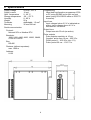
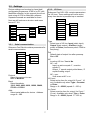
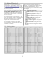
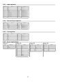
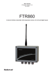
Nokeval Oy
07.02.2006
User manual
7181
Table of contents
1 Description................................................................................................................................. 3
2 Specifications............................................................................................................................. 4
3 Installing..................................................................................................................................... 5
3.1 Jumpers............................................................................................................................ 5
3.2 Connections...................................................................................................................... 6
3.3 Settings............................................................................................................................. 7
3.3.1 Serial communication.................................................................................................. 7
3.3.2 I/O lines....................................................................................................................... 7
3.3.3 Virtual channels........................................................................................................... 8
4 Operation................................................................................................................................... 9
4.1 Inputs................................................................................................................................. 9
4.1.1 Input lines.................................................................................................................... 9
4.1.2 Virtual input channels.................................................................................................. 9
4.2 Outputs.............................................................................................................................. 9
4.2.1 Output lines................................................................................................................. 9
4.2.2 Virtual output channels................................................................................................ 9
4.2.3 OneShot outputs....................................................................................................... 10
4.2.4 Pulse outputs............................................................................................................. 10
5 Serial communication.............................................................................................................. 11
5.1 SCL protocol................................................................................................................... 11
5.1.1 Serial communication settings................................................................................... 11
5.1.2 Command frameKomentopaketti.............................................................................. 11
5.1.3 Responce frame........................................................................................................ 11
5.1.4 Supported commands............................................................................................... 12
5.2 Modbus RTU protocol.................................................................................................... 13
5.2.1 Supported commands:.............................................................................................. 13
5.2.2 Holding registers....................................................................................................... 13
5.2.3 Input registers............................................................................................................ 14
5.2.4 Discrete Input registers............................................................................................. 14
5.2.5 Coil registers............................................................................................................. 14
5.2.6 Enum explanations.................................................................................................... 14
1 Description
I/O transmitter is designed for transfering state
information from process to PC by serial
communication and vice versa. Unit can
replace I/O cards inside PC. Wiring is simple
because of RS-485 bus.
Setting can be done by PC using MekuWin
software or by hand-held configuration
programmer 6790.
3
Transfering analog information from process
to PC can be done with transmitter 7100 or
RMD680. Using transmitter 7470 you can
transfer analog information from PC to
process.
2 Specifications
Supply voltage
Supply current
Oper. temperature
Storage temperature
Humidity
Weight
Terminals
Mounting
24 VDC, ±15 %
12 mA
0...60 °C
-20...+70 °C
0...95 %
55 g
detachable, 1.5 mm2
35 mm DIN rail
Programming
Hand-held configuration programmer 6790
or PC using RS-485 bus or jack on front
panel (using POL-RS232 cable or DCS772
converter).
Input lines
Input voltages below 3.5 V is indicated as
active. Input voltages above 4.5 V is
indicated as non active.
Serial communication:
Protocol:
Nokeval SCL or Modbus RTU
Output lines
Output can sink 50 mA (as active).
Baudrate:
1200, 2400, 4800, 9600, 19200, 38400,
57600 ot 115200
Pulse outputs
Pulse outputs resolution is 10 ms.
Oneshot: active time 10 ms – 655.35 s.
PWM: period 1 – 655.35 s (min. 1%).
Pulse: period 20 ms – 1310.71 s
Bus:
RS-485
Distance (without repeaters):
max. 1000 m
Address:
0-123
4
3 Installing
If factory defaults of RS-485 bus (3-wire
connection, no termination and programmable
baudrate) are not suitable, you have to
change the jumper settings. First you have to
open the case. Put the tip of screwdriver
between the right side panel and the frame.
Twist screwdriver upright. Change the settings
as shown in section 3.1. Close the case.
Do connections by section 3.2 (page 6).
Rest of settings can be done by Hand-held
configuration programmer 6790 or by
MekuWin software. Look section 3.3 (page 7).
Opening the case
3.1
Jumpers
RS-485 bus
3-wire connection
no termination
3-wire connection
termination
J6
2-wire connection
no termination
2-wire connection
termination
J2
Baudrate
Programmable
Fixed (9600)
RS-485 bus
Set the properties of RS-485 bus by jumper
J6. 2 or 3 wire connection, terminated or
not terminated.
5
Baudrate
By jumper J2 you can select programmable
or fixed (9600 baud) baudrate.
3.2
Connections
D1
RS-485
D0
I/O1
I/O2
1 kΩ
Com
Inpust:
Switch or
NPN/PNP-transistor
1
2
3
4
5
6
7
8
9
10
Powersupply
Connect 24 Vdc between terminals 1 and 2.
Terminal 1 is positive and terminal 2
negative.
RS-485
Connect RS-485 line D1 to terminal 3 and
line D0 to terminal 4. When 3 wire
connection is used connect potential
compensation line to terminal 2.
+
- 24 Vdc Powersupply
+24V
+24V ext.
I/O3
I/O4
0V ext.
Outputs:
Actuators 24 Vdc
max 50 mA
Input lines
Connect switch and NPN transistor
between terminal 10 (Com) and input line
(terminal 6-9). PNP transistor should be
connected between terminals 5 (24 Vcd)
and input line. Use 1kΩ pull-down resistor
from input line to terminal 10.
Output lines
Connect actuators between terminal 5 and
output line, terminals 6-9. When using
external powersupply for actuators connect
them between positive terminal of the
supply and output line. Connect negative
terminal of supply to terminal 10.
6
3.3
Settings
Device settings can be done by hand-held
configurator programmer 6790 or by PC with
MekuWin software. In this manual we will not
treat using of 6790 or MekuWin software.
Separate manuals are available for them.
Next we will look menu structure and menu
items of 7181.
I/O lines
Submenu Conf:I/O1-I/O4 contains parameters
for I/O lines. These settings will come active
avery time device is powered up or resetted.
Conf
Serial
Conf
Serial
3.3.2
Serial
I/O1
I/O1
I/O2
Type
I/O1
I/O1
Protocol
I/O3
Def
I/O2
Type
Baud
I/O4
NC
I/O3
Def
Addr
I/O4
NC
VCh1
Hi Count
Hi Count
VCh2
Lo Count
Lo Count
VCh3
VCh1
VCh1
VCh2
Mode
VCh3
First
VCh4
Last
3.3.1
VCh4
Serial communication
Submenu Conf:Serial contains parameters for
serial communication.
Def
Default state of output line after powerup.
On or Off.
Conf
Serial
Serial
I/O1
Protocol
I/O2
Baud
I/O3
Addr
Type
Select type of I/O line. Input (static input),
Output (static output), OneShot (single
pulse) tai Pulse (continuous pulse, PWM or
frequency).
NC
Inverting I/O line. Yes tai No.
I/O4
NC = no:
Input; as active equals '1', unactive
equals '0'.
Output; '1' equals output pulled down, '0'
equals floating output.
VCh1
VCh2
VCh3
VCh4
NC = yes:
Vica versa as NC = no.
Protocol
Select the protocol to use.
SCL or Modbus.
Hi Count
Select active time for output (Hi Count * 10
ms). Available only when Type = Oneshot
or Pulse.
Range = 0 – 65000 (equals 0 – 650 s).
Baud
Select baudirate.
1200, 2400, 4800, 9600, 19200, 38400,
57600 or 115200.
Lo Count
Select unactive time for output (Lo Count *
10 ms). Available only when Type = Pulse.
Range = 0 – 65000 (equals 0 – 650 s).
Addr
Select serial addres for device. Address
range 0 – 123.
7
3.3.3
Mode
Select format of virtual channel.
Bin, BCD or Gray.
Virtual channels
Submenu Conf:VCh1-VCh4 contains
parameters for virtual channels. You can
combine 1-4 I/O lines to one virtual channel.
So combined I/O lines are treat as binary
number of 1-4 bits. Note, virtual channel
output will override possible output line state
setting.
Dir
Direction of virtual channel. Input or
Output.
First
Select LSB I/O line for this virtual channel.
Note, type of I/O line should be Input tai
Output.
Conf
Serial
I/O1
Last
Select MSB I/O line for this virtual channel.
Note, type of I/O line should be Input tai
Output.
I/O2
I/O3
I/O4
VCh1
VCh2
VCh1
Mode
VCh3
Dir
VCh4
First
Last
8
4 Operation
Device is controlled via RS-485 bus using
either Nokeval SCL or Modbus RTU protocol.
Command list of SCL protocol is in section
5.1.4. Modbus registers are shown in section
5.2.
4.1
4.1.1
Inputs
Input lines
4.1.2
SCL commands
States of I/O lines can be read by commands:
Values of virtual input channels can be read
by commands:
Modbus registers
MEA CH x?
MEA SCAN x y
States of I/O lines can be read from Modbus
registers:
InputRegister 0
InputRegister 1
InputRegister 2
InputRegister 3
DiscreteInputRegister 0
DiscreteInputRegister 1
DiscreteInputRegister 2
DiscreteInputRegister 3
4.2.1
1-4 input lines can be combined to one virtual
channel to get binary number of 1-4 bits.
SCL commands
DI CH x ?
DI SCAN x y
4.2
Virtual input channels
Modbus registers
State of line 1.
State of line 2.
State of line 3.
State of line 4.
State of line 1.
State of line 2.
State of line 3.
State of line 4.
Values of virtual input channels can be read
from Modbus registers:
InputRegister 4
InputRegister 5
InputRegister 6
InputRegister 7
Value of Channe 1.
Value of Channe 2.
Value of Channe 3.
Value of Channe 4.
Outputs
Output lines
4.2.2
1-4 input lines can be combined to one virtual
channel to get binary number of 1-4 bits. Note,
virtual channel output will override possible
output line state setting.
SCL commands
States of output lines can be set by
commands:
DO CH x b
DO SCAN x y bx .. by
SCL command
Value of virtual output channel can be set by
command:
Modbus registers
States of output lines can be set to Modbus
registers:
CoilRegister 0
CoilRegister 1
CoilRegister 2
CoilRegister 3
Virtual output channels
OUT CH x b
Modbus registers
State of line 1.
State of line 2.
State of line 3.
State of line 4.
Value of virtual output channel can be set to
Modbus registers:
HoldingRegister 4
HoldingRegister 5
HoldingRegister 6
HoldingRegister 7
9
Value of Channel 1.
Value of Channel 2.
Value of Channel 3.
Value of Channel 4.
4.2.3
OneShot outputs
4.2.4
Output lines can be set as monostabile flipflop. Output will go active when command is
sent or modbus register is wrote. After given
period output line will go unactive. This
monostabile flip-flop is retriggerable.
Pulse outputs
Output lines can be set as astabile flip-flop.
Output will change state after user defined
periods.
SCL commands
Astabile operation will be initiated by
command:
SCL command
Monostabile operation will be initiated by
command:
PULSE x h l
PWM x p d
PERIOD x p
ONESHOT x h
Modbus registers
Modbus registers
Monostabile operation will be initiated by
writing to Modbus registers:
Astabile operation will be initiated by writing to
Modbus registers:
HoldingRegister 8
HoldingRegister 9
HoldingRegister 10
HoldingRegister 11
HoldingRegister 8
HoldingRegister 9
HoldingRegister 10
HoldingRegister 11
HoldingRegister 12
HoldingRegister 13
HoldingRegister 14
HoldingRegister 15
Trig line 1 and ON time.
Trig line 2 and ON time.
Trig line 3 and ON time.
Trig line 4 and ON time.
10
Line 1 ON time.
Line 2 ON time .
Line 3 ON time .
Line 4 ON time.
Line 1 OFF time.
Line 2 OFF time.
Line 3 OFF time.
Line 4 OFF time.
5 Serial communication
Device is controlled vie RS-485 bus. In RS485 bus can be connected up to 32 devices.
By using repeaters you can extend the RS485 bus. For each segment of RS-485 bus
you can connect 32 devices. Maximum length
of segment is about 1 km. RS-485 bus
topology shoul be chain. Length of brances
can be max. 2 m.
5.1
5.1.1
RS-485
dev
Branch
max. 2 m
dev
dev
Bus topology: Chain
Actual command
Serial communication settings
The control characters presented below are
one byte each, and every character (letter or
number or space) in the command takes one
byte as well.
Command frame
The actual command is composed of letters
and numbers and is human readable. The
commands recognized by a device are
specified in its user manual; however some
most common commands are represented in
this manual also.
ID
dev
SCL protocol
SCL protocol uses 8N1 bit protocol, i.e. 8 data
bits, none parity, and one stop bit. Baud rates
depend on device in concern, see its user
manual. Recommended baud rate is 9600 bits
per second.
5.1.2
dev
command
ETX
BCC
Start byte ID
The start byte is the only byte in SCL protocol
that has the most significant bit set. This
identifies that a completely new command
frame is to come. The ID is formed from the
device address (0-123) by setting the most
significant bit, or by adding 128 (80h) to the
address.
Address 126 (ID byte 126+128=254) is
reserved for general call. The purpose of this
is to provide a connection to a device the
address of which is not known. When using
this procedure, there should be only one
device on the bus. This is supported by
certain products only.
Note: The ID is one byte, not a series of
separate numbers (e.g. ‘1’, ‘2’, and ‘8’).
11
The command is sent as is. The command
can be for example ”MEA CH 1 ?”.
End byte ETX
The command is terminated with single byte
with value of 3 (03h), this is called ETX. Do
not send Ascii character ‘3’.
Checksum byte BCC
The target device calculates the checksum
and compares it to the BCC sent with the
command to see if the command has transfer
errors. The BCC is a single byte that is
calculated using XOR operation (bitwise
exclusive OR) on every byte in the actual
command and ETX (ID is excluded!).
Some Nokeval devices have an option to
disable the BCC, because it may be too
difficult to calculate in some applications.
Example of a command frame
We want to send a command MEA CH 1 ? to
a device with address 1. The command frame
is represented below with the hexadecimal
values of the bytes:
<ID> M E A C H 1 ? <ETX> <BCC>
81 4D 45 41 20 43 48 20 31 20 3F 03 6F
BCC is calculated by applying XOR on all
bytes except ID (× represents XOR operation):
4D×45×41×20×43×48×20×31×20×3F×03 = 6F
5.1.3
Responce frame
Kun laite saa komennon, se vastaa
vastauspaketilla. Niitä on kahta lajia,
normaalia vastausta (ACK) ja virhevastausta
(NAK).
Normal response
Error response
The response packet starts with response
start byte ACK (06h), then comes the actual
response, ETX (03h), and finally the BCC.
If there is error in the transfer or in the
command, the device sends an error
response. It is started with NAK byte (15h)
instead of ACK, and the actual response is an
integer consisting of Ascii characters ‘0’-‘9’.
ACK
response
ETX
BCC
BCC is calculated by applying XOR on all
response frame bytes, including the start byte
ACK or NAK!
Assume the panel meter/transmitter has a
result 21.3. It will answer to the MEA
command with a response frame:
<ACK> 2 1
06
.
Error number
ETX
BCC
0 Device busy – try again later
1 Buffer overflow – too long command
3 <ETX> <BCC>
32 31 2E 33 03
NAK
The precise meaning of the error number is
specified in the device user manual. Most
common error number meanings are:
2 Timeout – command interrupted
1B
Note that some commands cause the device
to send an empty response
(<ACK><ETX><BCC>) to indicate that the
command has been received but there is
nothing to say (kind of OK response). DISP,
OUT, and DO are this kind of commands.
3 BCC error in command frame – disturbance
in transmission
4 Command not recognized
5 First parameter invalid
6 Second parameter invalid
7 etc
5.1.4
Supported commands
TYPE ?
Palauttaa laitteen tyypin ja versio numeron.
Esim. 7181 V0.1
SN ?
Palauttaa laitteen sarjanumeron.
MEA SCAN x y
Palauttaa virtuaalikanavien x-y arvot.
OUT CH x v
Asettaa virtuaalikanavan x arvoksi v:n.
DI CH x
Palauttaa tulolinjan x tilan.
ONESHOT x h
Asettaa lähtölinjan x ylhäälläoloajaksi
h*10ms
DI SCAN x y
Palauttaa tulolinjojen x-y tilan.
Esim. ”0 1 1 0”
PULSE x h l
Asettaa lähtölinjan x ylhäälläoloajaksi
h*10ms ja alhaallaoloajaksi l*10ms.
DO CH x b
Asettaa lähtölinjan x tilaksi b:n
PWM x p d
Asettaa lähtölinjan x jaksonajaksi p*10ms ja
pulssisuhteeksi d%.
DO SCAN x y b1 b2 .. bn
Asettaa lähtölinjojen x-y tiloiksi b1, b2, ...
PERIOD x p
Asettaa lähtölinjan x jaksonajaksi p*10ms
pulssisuhteella 50%.
MEA CH x
Palauttaa virtuaalikanavan x arvon
12
5.2
Modbus RTU protocol
Modbus RTU is commonly used protocol in
instrumentation. Specifications can be found
at http://www.modbus.org/specs.php. In this
document we treat Modbus protocol relating to
this device properties.
When the settings are changed by writing to a
Holding register, the settings are changed to
the non-voltatile EEPROM memory
immediately. It might take several dozens of
milliseconds for the transmitter to respond to
the next command.
The maximum length of the command is 150
bytes. The maximum length of the response is
the same. This sets the limit to number of
registers with commands 3, 4, and 16.
The command 17 will return 0x11 <byte
count> 0x00 0xFF, followed with ”7181 V1.0
A123456”, for example.
5.2.2
When the serial connection settings are
changed, the changes do not affect until the
transmitter is powered down. This is to
prevent breaking the connection while making
the changes.
5.2.1
•
•
•
•
•
•
•
Supported commands:
2 Read Discrete Inputs: reading the digital
inputs.
3 Read Holding Registers: reading the
settings.
4 Read Input Registers: reading the input
readings.
6 Write Single Register: changing the
settings and the Ext channel.
16 Write Multiple registers: changing the
settings.
17 Report Slave ID: checking the device
type.
109 Meku: Mekuwin configuration software
uses this.
Holding registers
Register
Name
Type
Values
Register
Name
Type
Values
0
Ctrl\DO1
BYTE
Unsigned 0...1
110
Conf\I/O2\NC
BOOL
1
Ctrl\DO2
BYTE
Unsigned 0...1
111
Conf\I/O2\Hi Count
WORD
Unsigned
2
Ctrl\DO3
BYTE
Unsigned 0...1
112
Conf\I/O2\Lo Count
WORD
Unsigned
3
Ctrl\DO4
BYTE
Unsigned 0...1
113
Conf\I/O3\Type
ENUM
See table E3
4
Ctrl\VCh1 Out
BYTE
Unsigned 0...15
114
Conf\I/O3\Def
BOOL
5
Ctrl\VCh2 Out
BYTE
Unsigned 0...15
115
Conf\I/O3\NC
BOOL
6
Ctrl\VCh3 Out
BYTE
Unsigned 0...15
116
Conf\I/O3\Hi Count
WORD
Unsigned
7
Ctrl\VCh4 Out
BYTE
Unsigned 0...15
117
Conf\I/O3\Lo Count
WORD
Unsigned
8
Ctrl\Cntr1Hi
WORD
Unsigned
118
Conf\I/O4\Type
ENUM
See table E3
9
Ctrl\Cntr2Hi
WORD
Unsigned
119
Conf\I/O4\Def
BOOL
10
Ctrl\Cntr3Hi
WORD
Unsigned
120
Conf\I/O4\NC
BOOL
11
Ctrl\Cntr4Hi
WORD
Unsigned
121
Conf\I/O4\Hi Count
WORD
Unsigned
12
Ctrl\Cntr1Lo
WORD
Unsigned
122
Conf\I/O4\Lo Count
WORD
Unsigned
13
Ctrl\Cntr2Lo
WORD
Unsigned
123
Conf\VCh1\Mode
ENUM
See table E4
14
Ctrl\Cntr3Lo
WORD
Unsigned
124
Conf\VCh1\First
BYTE
Unsigned 1...4
15
Ctrl\Cntr4Lo
WORD
Unsigned
125
Conf\VCh1\Last
BYTE
Unsigned 1...4
100
Conf\Serial\Protocol
ENUM
See table E1
126
Conf\VCh2\Mode
ENUM
See table E4
101
Conf\Serial\Baud
ENUM
See table E2
127
Conf\VCh2\First
BYTE
Unsigned 1...4
102
Conf\Serial\Addr
BYTE
Unsigned 0...123
128
Conf\VCh2\Last
BYTE
Unsigned 1...4
103
Conf\I/O1\Type
ENUM
See table E3
129
Conf\VCh3\Mode
ENUM
See table E4
104
Conf\I/O1\Def
BOOL
130
Conf\VCh3\First
BYTE
Unsigned 1...4
105
Conf\I/O1\NC
BOOL
131
Conf\VCh3\Last
BYTE
Unsigned 1...4
106
Conf\I/O1\Hi Count
WORD
Unsigned
132
Conf\VCh4\Mode
ENUM
See table E4
107
Conf\I/O1\Lo Count
WORD
Unsigned
133
Conf\VCh4\First
BYTE
Unsigned 1...4
108
Conf\I/O2\Type
ENUM
See table E3
134
Conf\VCh4\Last
BYTE
Unsigned 1...4
109
Conf\I/O2\Def
BOOL
13
5.2.3
Input registers
Register
Name
Type
Values
0
Mon\I1
BYTE
Unsigned 0...1
1
Mon\I2
BYTE
Unsigned 0...1
2
Mon\I3
BYTE
Unsigned 0...1
3
Mon\I4
BYTE
Unsigned 0...1
4
Mon\VCh1 In
BYTE
Unsigned 0...15
5
Mon\VCh2 In
BYTE
Unsigned 0...15
6
Mon\VCh3 In
BYTE
Unsigned 0...15
7
Mon\VCh4 In
BYTE
Unsigned 0...15
5.2.4
Discrete Input registers
Register
Name
Type
Values
0
Mon\I1
BYTE
Unsigned 0...1
1
Mon\I2
BYTE
Unsigned 0...1
2
Mon\I3
BYTE
Unsigned 0...1
3
Mon\I4
BYTE
Unsigned 0...1
5.2.5
Coil registers
Register
Name
Type
Values
0
Ctrl\I1
BYTE
Unsigned 0...1
1
Ctrl\I2
BYTE
Unsigned 0...1
2
Ctrl\I3
BYTE
Unsigned 0...1
3
Ctrl\I4
BYTE
Unsigned 0...1
5.2.6
Enum explanations
Table E1
Value
Table E2
Protocol
Value
Table E3
Baud
Value
Table E4
Type
Value
Mode
0
SCL
0
1200
0
Input
0
Off
1
Modbus
1
2400
1
Output
1
Bin
2
4800
2
OneShot
2
Bcd
3
9600
3
Pulse
3
Gray
4
19200
5
38400
6
57600
7
115200
14
15
Manufacturer:
Nokeval Oy
Yrittäjäkatu 12
37100 Nokia
FINLAND
Tel. 03-3424800
Fax. 03.3422066
Email: [email protected]
http:
//www.nokeval.com
16